


All Exams >
Civil Engineering (CE) >
Design of Steel Structures >
All Questions
All questions of Compression Members for Civil Engineering (CE) Exam

The thickness of lacing bars for single lacing, system should not be less thanwhere l = length between the inner end of connections.- a)l/40
- b)l/50
- c)l/60
- d)l/70
Correct answer is option 'A'. Can you explain this answer?
The thickness of lacing bars for single lacing, system should not be less than
where l = length between the inner end of connections.
a)
l/40
b)
l/50
c)
l/60
d)
l/70

|
Swara Gupta answered |
Minimum thickness of lacing bars,
 for single lacing
 for double lacing riveted or welded at intersection.
for single lacing for double lacing riveted or welded at intersection.Which one of the following is a compression member?- a)Purlin
- b)Boom
- c)Girt
- d)Tie
Correct answer is option 'B'. Can you explain this answer?
Which one of the following is a compression member?
a)
Purlin
b)
Boom
c)
Girt
d)
Tie
|
|
Pallabi Kulkarni answered |
Strut is a compression member used in the roof truss and bracing. They are of small span and may be vertical or inclined.
The principal rafter is a top chord member in a roof truss and boom is the principal compression member in a crane.
Column, stanchion or post is a vertical compression member supporting flats or girders in a building.
The principal rafter is a top chord member in a roof truss and boom is the principal compression member in a crane.
Column, stanchion or post is a vertical compression member supporting flats or girders in a building.
If 20 mm rivets are used in lacing bars, then the minimum width of lacing bar should be- a)40 mm
- b)60 mm
- c)80 mm
- d)100 mm
Correct answer is option 'B'. Can you explain this answer?
If 20 mm rivets are used in lacing bars, then the minimum width of lacing bar should be
a)
40 mm
b)
60 mm
c)
80 mm
d)
100 mm
|
|
Pallabi Chavan answered |
Minimum width of lacing bar
To determine the minimum width of the lacing bar, we need to consider the size of the rivets used in the lacing bars.
Given:
Size of the rivets used in lacing bars = 20 mm
Explanation:
The minimum width of the lacing bar is determined by the number of rivets that can be accommodated in the width.
To calculate the number of rivets that can be accommodated in the width, we divide the width by the size of the rivets.
Let's consider the options given:
a) 40 mm:
If the lacing bar width is 40 mm, the number of rivets that can be accommodated is 40/20 = 2 rivets.
b) 60 mm:
If the lacing bar width is 60 mm, the number of rivets that can be accommodated is 60/20 = 3 rivets.
c) 80 mm:
If the lacing bar width is 80 mm, the number of rivets that can be accommodated is 80/20 = 4 rivets.
d) 100 mm:
If the lacing bar width is 100 mm, the number of rivets that can be accommodated is 100/20 = 5 rivets.
Conclusion:
From the above calculations, it can be observed that the minimum width of the lacing bar should be 60 mm (Option B) in order to accommodate 3 rivets with a size of 20 mm each.
Consider the following statements for the design of a laced column:
1) In a bolted construction, the minimum width of the lacing bar shall be three times the nominal diameter of the end bolt.
2) The thickness of the flat of a single lacing system shall be not less than one-fortieth of its effective length
3) The angle of inclination of the lacing bar should be less than 40° with the axis of the built-up column
4) The lacing shall be designed for a transverse shear of 2.5% of the axial load on the column
Which of the above statements are correct?
- a)1 only
- b)1 and 3
- c)2 and 4
- d)1, 2 and 4
Correct answer is option 'D'. Can you explain this answer?
Consider the following statements for the design of a laced column:
1) In a bolted construction, the minimum width of the lacing bar shall be three times the nominal diameter of the end bolt.
2) The thickness of the flat of a single lacing system shall be not less than one-fortieth of its effective length
3) The angle of inclination of the lacing bar should be less than 40° with the axis of the built-up column
4) The lacing shall be designed for a transverse shear of 2.5% of the axial load on the column
Which of the above statements are correct?
a)
1 only
b)
1 and 3
c)
2 and 4
d)
1, 2 and 4
|
|
Prerna Menon answered |
Correct Option is D.
For the design of laced columns:
I) The sections to be laced are so spaced that the radius of gyration of the section about the axis perpendicular to the plane of lacing is not less than the radius of gyration about the axis in the plane of lacing.
II) The effective slenderness ratio should be taken as 1.05 times the actual maximum slenderness ratio, in order to account for shear deformation effect.
III) Angle of inclination of the lacing bar should be kept between 40° - 70°. Lacing is most efficient between 35° to 45°, but angle less than 40° would result in a higher length of lacing bar which may then to buckle individually.
IV) The maximum spacing of the lacing bar should be such that the minimum slenderness ratio of the component member should not be greater than 50 or 0.7 times the slenderness ratio of the member.
V) The lacing for compression members should be proportioned to resist transverse shear equal to 2.5% of the axial force in the column.
VI) The minimum flat width should not be less than three times the nominal diameter of the end connector.
VII) The thickness of the lacing flat for a single lacing system should be less than 1/40 of its effective length and for a double lacing system, it should be less than 1/60 of its effective length.
VIII) The slenderness ratio of the lacing bar should be less than 145.
X) The effective length of lacing bar is the length between the inner end rivets/bolts for a single lacing system and 0.7 times this distance for a double lacing system.
Lacing bars in a steel column should be designed to resist- a)bending moment due to 2.5% of the column load
- b)shear force due to 2.5% of the column load
- c)2.5% of the column load
- d)Both (a) and (b)
Correct answer is option 'B'. Can you explain this answer?
Lacing bars in a steel column should be designed to resist
a)
bending moment due to 2.5% of the column load
b)
shear force due to 2.5% of the column load
c)
2.5% of the column load
d)
Both (a) and (b)

|
Shounak Saini answered |
The lacing of compression members should be designed to resist a transverse shear, V = 2.5% of axial force in the member.
For single lacing system on two parallel faces, the force (compressive or tensile) in each bar,

For double lacing system on two parallel planes, the force (compressive or tensile) in each bar,

For single lacing system on two parallel faces, the force (compressive or tensile) in each bar,
For double lacing system on two parallel planes, the force (compressive or tensile) in each bar,
For a compression member having the same effective length about any cross-sectional axis, the most preferred section from the point of view of strength is- a)A box
- b)An I-section
- c)A circular tube
- d)A single angle
Correct answer is option 'A'. Can you explain this answer?
For a compression member having the same effective length about any cross-sectional axis, the most preferred section from the point of view of strength is
a)
A box
b)
An I-section
c)
A circular tube
d)
A single angle
|
|
Gitanjali Menon answered |
Slenderness ratio, 
Lesser the value of λ (greater radius of gyration r), the column can take more load. Maximum radius of gyration is obtained when material is farthest from centroid. Therefore box section is best.
Lesser the value of λ (greater radius of gyration r), the column can take more load. Maximum radius of gyration is obtained when material is farthest from centroid. Therefore box section is best.
Slenderness ratio of the splices for compression members is- a)0
- b)145
- c)180
- d)350
Correct answer is option 'A'. Can you explain this answer?
Slenderness ratio of the splices for compression members is
a)
0
b)
145
c)
180
d)
350
|
|
Tanishq Menon answered |
Splices used in compression members are assumed to act as short columns with zero slender ness ratio.
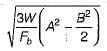
An electric pole 5 m high is fixed into the foundation. It carries a wire at the top and is free to move sideways. The effective length of the pole is- a)3.25 m
- b)4,0m
- c)5.0 m
- d)10.0 m
Correct answer is option 'B'. Can you explain this answer?
An electric pole 5 m high is fixed into the foundation. It carries a wire at the top and is free to move sideways. The effective length of the pole is
a)
3.25 m
b)
4,0m
c)
5.0 m
d)
10.0 m
|
|
Milan Ghosh answered |
It is equivalent to a compression member whose one end is fixed against rotation and position and the other and neither restrained against rotation nor fixed in position in the direction perpendicular to wire. So effective length = 2L = 10 m.
In the direction of wire, the pole is hinged at wire end so effective length = 0.8L = 4.0 m.
In the direction of wire, the pole is hinged at wire end so effective length = 0.8L = 4.0 m.
In a gusseted base, when the end of the column is machined for complete bearing on the base plate, the axial load is assumed to be transferred to the base plate- a)fully by direct bearing
- b)fully through the fastenings
- c)50% by direct bearing and 50% through fastenings
- d)75% by direct bearing and 25% through fastenings
Correct answer is option 'C'. Can you explain this answer?
In a gusseted base, when the end of the column is machined for complete bearing on the base plate, the axial load is assumed to be transferred to the base plate
a)
fully by direct bearing
b)
fully through the fastenings
c)
50% by direct bearing and 50% through fastenings
d)
75% by direct bearing and 25% through fastenings
|
|
Ashwin Kulkarni answered |
If the column ends and gusset materials are not faced/machined for complete be a ring, the fasteners are designed for the total forces to be transferred. If they are faced/machined for complete bearing, 50% of the forces are transferred directly by the column and 50% through the fasteners
In ISMC 400 channels placed back to back at a spacing of 26 cm carry an axial load of 160 tonnes. The lacing system should be designed to resist a transverse shear of- a)16 tonnes
- b)12 tonnes
- c)8 tonnes
- d)4 tonnes
Correct answer is option 'D'. Can you explain this answer?
In ISMC 400 channels placed back to back at a spacing of 26 cm carry an axial load of 160 tonnes. The lacing system should be designed to resist a transverse shear of
a)
16 tonnes
b)
12 tonnes
c)
8 tonnes
d)
4 tonnes

|
Avik Chaudhary answered |
Given information:
- 400 channels are placed back to back at a spacing of 26 cm.
- The axial load carried by the channels is 160 tonnes.
Objective:
- To design a lacing system that can resist a transverse shear.
Approach:
- Calculate the total axial load carried by the channels.
- Determine the maximum transverse shear that the lacing system should be able to resist.
- Select the lacing system that can resist the required transverse shear.
Calculations:
The total axial load carried by the channels can be calculated using the formula:
Total Load = Number of Channels * Load per Channel
Given:
Number of Channels = 400
Load per Channel = 160 tonnes
Total Load = 400 * 160 = 64,000 tonnes
Determination of maximum transverse shear:
The spacing between the channels is given as 26 cm. To determine the maximum transverse shear, we need to convert this spacing into meters.
Spacing in meters = 26 cm / 100 = 0.26 m
The maximum transverse shear can be calculated using the formula:
Transverse Shear = Total Load / Spacing
Transverse Shear = 64,000 tonnes / 0.26 m = 246,153.85 tonnes/m
Selection of lacing system:
We need to select a lacing system that can resist a transverse shear of 4 tonnes.
Based on the given options, the correct answer is option 'D' (4 tonnes).
Therefore, the lacing system should be designed to resist a transverse shear of 4 tonnes.
Two ISMC 400 are placed back to back at a spacing of 300 mm and carry an axial ioad.of 160 kN. As per IS : 800 1984 its lacing system should be designed to resist a transverse shear of- a)1.6 kN
- b)4.00 kN
- c)8 kN
- d)16.0 kN
Correct answer is option 'B'. Can you explain this answer?
Two ISMC 400 are placed back to back at a spacing of 300 mm and carry an axial ioad.of 160 kN. As per IS : 800 1984 its lacing system should be designed to resist a transverse shear of
a)
1.6 kN
b)
4.00 kN
c)
8 kN
d)
16.0 kN
|
|
Ananya Sharma answered |
Given information:
- Two ISMC 400 sections are placed back to back.
- The spacing between the sections is 300 mm.
- The axial load carried by the sections is 160 kN.
Objective:
To determine the transverse shear force that the lacing system should be designed to resist.
Formula:
The transverse shear force can be calculated using the formula:
Transverse shear force (V) = (axial load / spacing) / 2
Calculation:
Given that the axial load is 160 kN and the spacing is 300 mm (or 0.3 m), we can calculate the transverse shear force as follows:
V = (160 kN / 0.3 m) / 2
V = 266.67 kN
Answer:
Therefore, the lacing system should be designed to resist a transverse shear force of 4.00 kN (option B).
Which of the following is not a compression member?- a)Strut
- b)Tie
- c)Rafter
- d)Boom
Correct answer is option 'B'. Can you explain this answer?
Which of the following is not a compression member?
a)
Strut
b)
Tie
c)
Rafter
d)
Boom
|
|
Shalini Deshpande answered |
Strut is a compression member used in the roof truss and bracing.
Rafter or principal rafter is a top chord member in a roof truss.
Boom is the principal compression member in a crane.
Tie rods are sag rods provided at the crown of truss used in industrial sheds. These cut as tension members and resist the tangential components from the two sides of roof truss.
Rafter or principal rafter is a top chord member in a roof truss.
Boom is the principal compression member in a crane.
Tie rods are sag rods provided at the crown of truss used in industrial sheds. These cut as tension members and resist the tangential components from the two sides of roof truss.
Which one among the following is the correct ratio of effective length to actual length of a discontinuous angle strut, if ends are welded?- a)0.65
- b)0.85
- c)1.0 .
- d)1.2
Correct answer is option 'B'. Can you explain this answer?
Which one among the following is the correct ratio of effective length to actual length of a discontinuous angle strut, if ends are welded?
a)
0.65
b)
0.85
c)
1.0 .
d)
1.2
|
|
Aniket Mehta answered |
For single angle discontinuous,
(i) One rivet or bolt - Effective length is the distance between the centres of end fastenings
(ii) Two or more rivets or welding - Effective length is 0.85 times the distance between node points.
(i) One rivet or bolt - Effective length is the distance between the centres of end fastenings
(ii) Two or more rivets or welding - Effective length is 0.85 times the distance between node points.
Which one of the following values represents the maximum slenderness ratio of any connection member which normally acts as a tie in a roof truss but can be subjected to possible reversal of stresses from the action of wind or seismic force?- a)150
- b)200
- c)250
- d)350
Correct answer is option 'D'. Can you explain this answer?
Which one of the following values represents the maximum slenderness ratio of any connection member which normally acts as a tie in a roof truss but can be subjected to possible reversal of stresses from the action of wind or seismic force?
a)
150
b)
200
c)
250
d)
350
|
|
Navya Kaur answered |
Slenderness ratio for a connection member acting as a tie in a roof truss:
The maximum slenderness ratio for a connection member that normally acts as a tie in a roof truss but can be subjected to possible reversal of stresses from the action of wind or seismic force is 350. This value represents the maximum ratio of the unsupported length of the member to its least radius of gyration.
Understanding slenderness ratio:
- The slenderness ratio is a measure of how slender or slender a member is relative to its ability to carry compressive loads without buckling.
- It is calculated as the ratio of the unsupported length of the member to its least radius of gyration.
Significance of maximum slenderness ratio of 350:
- A maximum slenderness ratio of 350 indicates that the member can withstand higher levels of compressive loads without buckling, making it suitable for use as a tie in a roof truss.
- Members with higher slenderness ratios are less prone to buckling and can safely carry loads even under the action of wind or seismic forces.
In conclusion, a maximum slenderness ratio of 350 is the ideal value for a connection member acting as a tie in a roof truss that may be subjected to possible reversal of stresses from wind or seismic forces. This value ensures the structural integrity and stability of the member under varying loading conditions.
Which one of the following pairs is correctly matched?- a)Truss : Bending
- b)Beam : Twisting
- c)Column : Buckling
- d)Shaft : Shortening
Correct answer is option 'C'. Can you explain this answer?
Which one of the following pairs is correctly matched?
a)
Truss : Bending
b)
Beam : Twisting
c)
Column : Buckling
d)
Shaft : Shortening
|
|
Nikhil Majumdar answered |
Column : Buckling
Explanation:
Column:
A column is a structural member that primarily carries axial compression loads. It is designed to provide vertical support to the imposed loads and transfer them to the foundation. Columns are commonly used in buildings and other structures to support the weight of the structure and resist compressive forces.
Buckling:
Buckling is a structural failure mode that occurs when a slender column or beam, under compression, fails due to instability. It is characterized by a sudden lateral deflection or bending of the column or beam. Buckling can occur when the compressive load exceeds the critical load, which depends on the column's length, cross-sectional properties, and the material's modulus of elasticity.
Matching:
The correct matching pair in the given options is "Column : Buckling." Columns are primarily susceptible to buckling failure, especially when they are slender and subjected to compressive loads.
Incorrect Options:
a) Truss : Bending
A truss is a structural framework composed of triangular units connected at joints. Trusses are commonly used to support roofs, bridges, and other structures. However, trusses are primarily designed to resist axial forces, such as tension and compression, rather than bending moments.
b) Beam : Twisting
A beam is a structural element that primarily resists bending moments. Beams are used to support loads and transfer them to the columns or walls. Twisting is not a typical failure mode for beams. Beams are more prone to bending and shear failures.
d) Shaft : Shortening
A shaft is a long, cylindrical structural element used to transmit torque and rotational motion. Shortening is not a characteristic failure mode for shafts. Shafts are designed to withstand torsional and bending loads, rather than compressive loads that lead to shortening.
Therefore, the correct matching pair is "Column : Buckling."
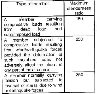
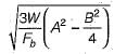
As per IS : 800, the thickness of slab base is given byWhere A and B are larger and smaller projections respectively of plate beyond column, W is the pressure on the underside of base and Fb is permissible bending stress in slab bases.- a)

- b)
- c)
- d)

Correct answer is option 'B'. Can you explain this answer?
As per IS : 800, the thickness of slab base is given by
Where A and B are larger and smaller projections respectively of plate beyond column, W is the pressure on the underside of base and Fb is permissible bending stress in slab bases.
a)
b)
c)
d)

|
Mani Shanker answered |
S
Gusset plate is provided in column base connection to- a)Reduce pressure that comes from underlying material to base plate
- b)Reduce thickness of base plate by reducing overhanging length
- c)Increase load carrying capacity of column
- d)Both (b) and (c)
Correct answer is option 'B'. Can you explain this answer?
Gusset plate is provided in column base connection to
a)
Reduce pressure that comes from underlying material to base plate
b)
Reduce thickness of base plate by reducing overhanging length
c)
Increase load carrying capacity of column
d)
Both (b) and (c)
|
|
Srestha Khanna answered |
Understanding Gusset Plates in Column Base Connections
Gusset plates play a crucial role in the structural integrity and efficiency of column base connections. Their design and application serve specific purposes, particularly in reducing the material requirements while maintaining load capacity.
Purpose of Gusset Plates
- Material Efficiency: By employing a gusset plate, engineers can effectively reduce the thickness of the base plate. This is achieved by minimizing the overhanging length.
- Load Distribution: The gusset plate facilitates better distribution of loads from the column to the foundation, allowing for a more efficient design without compromising structural integrity.
Why Option (B) is Correct
- Reduction of Overhanging Length: The gusset plate allows the base plate to be thinner by providing lateral support. This means that less material is needed, leading to a reduction in the overall weight of the connection.
- Maintaining Load Capacity: Although the gusset plate reduces the thickness of the base plate, it does not compromise the load-carrying capacity. Instead, it allows the design to be optimized, ensuring that the structure can still support the intended loads effectively.
Conclusion
In conclusion, the use of gusset plates in column base connections primarily serves to reduce the thickness of the base plate while maintaining or even increasing the load-carrying capacity. This makes option (B) the correct answer, as it encapsulates the functional advantages of using gusset plates in structural engineering applications.
The maximum slenderness ratio of a compression member carrying both dead and superimposed load is- a)180
- b)200
- c)250
- d)350
Correct answer is option 'A'. Can you explain this answer?
The maximum slenderness ratio of a compression member carrying both dead and superimposed load is
a)
180
b)
200
c)
250
d)
350
|
|
Devansh Banerjee answered |
Understanding Maximum Slenderness Ratio
The slenderness ratio is a critical parameter in structural engineering, particularly for compression members. It is defined as the ratio of the effective length of the member to its radius of gyration.
Definition of Slenderness Ratio
- Formula:
\[ \text{Slenderness Ratio} = \frac{L_{eff}}{r} \]
where \( L_{eff} \) is the effective length and \( r \) is the radius of gyration.
Importance of Slenderness Ratio
- A higher slenderness ratio indicates that the member is more slender and susceptible to buckling.
- The slenderness ratio affects the load-carrying capacity of the member.
Maximum Slenderness Ratio for Compression Members
- According to design codes, the maximum slenderness ratio for compression members carrying both dead and superimposed loads is 180.
Reason for Limitation
- Limiting the slenderness ratio helps ensure stability and prevent buckling.
- Compression members with a slenderness ratio greater than 180 may not have adequate strength and stability under load conditions.
Conclusion
- Therefore, for the safe design of compression members in structural applications, adhering to a maximum slenderness ratio of 180 is crucial. This ensures that the member can safely carry the imposed loads without the risk of buckling or failure, thereby ensuring structural integrity and safety.
The channels or angles in the compression chords of the steel truss girder bridges are turned outward in order to increase- a)cross-sectional area
- b)section modulus
- c)torsional constant
- d)radius of gyration
Correct answer is option 'D'. Can you explain this answer?
The channels or angles in the compression chords of the steel truss girder bridges are turned outward in order to increase
a)
cross-sectional area
b)
section modulus
c)
torsional constant
d)
radius of gyration

|
Rhea Dasgupta answered |
Explanation:
Steel truss girder bridges are designed to carry heavy loads and resist various types of forces, such as bending, shear, and torsion. The compression chords of a truss girder bridge are the upper chords that are subjected to compressive forces. The channels or angles in the compression chords are turned outward for a specific reason.
Here are the details of why the channels or angles in the compression chords of the steel truss girder bridges are turned outward in order to increase the radius of gyration.
Definition of Radius of Gyration:
Radius of Gyration (k) is a parameter used in structural engineering to measure the distribution of a section's area in relation to an axis. It is defined as the square root of the ratio of the moment of inertia of the section about an axis to its cross-sectional area.
Formula to calculate the Radius of Gyration:
k = √(I/A)
Where, I = moment of inertia and A = cross-sectional area
Importance of Radius of Gyration:
The radius of gyration is an important parameter in determining the strength and stability of a structural member. It affects the member's ability to resist buckling and bending under load.
Channels or Angles turned outward to increase the Radius of Gyration:
When the channels or angles in the compression chords of a steel truss girder bridge are turned outward, the cross-sectional area of the chord increases. This, in turn, increases the moment of inertia of the chord about its centroidal axis. As a result, the radius of gyration of the chord also increases.
The increase in the radius of gyration makes the chord more resistant to buckling and bending under load. It also reduces the amount of deflection in the chord, which improves the overall stiffness and stability of the bridge.
Conclusion:
In conclusion, the channels or angles in the compression chords of steel truss girder bridges are turned outward to increase the radius of gyration. This improves the strength, stability, and stiffness of the bridge, making it better equipped to handle heavy loads and resist various types of forces.
The maximum slenderness ratio of a steel column, the design of which is governed by wind or seismic forces is- a)150
- b)180
- c)250
- d)350
Correct answer is option 'C'. Can you explain this answer?
The maximum slenderness ratio of a steel column, the design of which is governed by wind or seismic forces is
a)
150
b)
180
c)
250
d)
350
|
|
Rahul Chauhan answered |
Understanding Slenderness Ratio in Steel Columns
The slenderness ratio is a crucial parameter in the design of steel columns, particularly when subjected to lateral forces such as wind or seismic activity. It is defined as the effective length of the column divided by its radius of gyration.
Maximum Slenderness Ratio
- The maximum slenderness ratio for steel columns is determined by design codes to ensure stability and structural integrity.
- For columns subjected primarily to wind or seismic forces, the slenderness ratio limit is set at 250.
Reasons for the Limit
- Stability Concerns: A higher slenderness ratio indicates that the column is more susceptible to buckling under lateral loads. Limiting the ratio helps prevent buckling failures.
- Material Behavior: Steel exhibits different behavior under axial loads versus lateral loads. The limit of 250 ensures that the column can effectively carry both types of loads.
- Design Codes: Various design codes, such as the AISC (American Institute of Steel Construction) and Eurocode, specify the slenderness ratio limits based on empirical studies and structural performance.
Comparison with Other Values
- Options such as 150, 180, and 350 do not align with established engineering practices for wind or seismic designs.
- A slenderness ratio of 150 is more restrictive and typically applies to compression members in bracing systems, whereas 350 might be applied in special conditions but not for general wind or seismic designs.
Conclusion
In summary, the correct answer for the maximum slenderness ratio of a steel column governed by wind or seismic forces is 250. This limit is essential for ensuring the safety and effectiveness of structural designs under lateral loading conditions.
Slenderness ratio for single angle single riveted strut should be less than- a)180
- b)250
- c)300
- d)350
Correct answer is option 'A'. Can you explain this answer?
Slenderness ratio for single angle single riveted strut should be less than
a)
180
b)
250
c)
300
d)
350

|
Ishani Chauhan answered |
Slenderness Ratio for Single Angle Single Riveted Strut
The slenderness ratio is an important factor in the design of struts. It is defined as the ratio of the effective length of the strut to the least radius of gyration of its cross-section. In the case of a single angle single riveted strut, the slenderness ratio should be less than 180 for safe and efficient design.
What is a Single Angle Single Riveted Strut?
A single angle single riveted strut is a structural member that is used to resist compressive forces in a structure. It consists of a single angle section that is connected to other members through rivets. The strut is designed to carry compressive loads and is subjected to buckling under the action of compressive forces.
Why is Slenderness Ratio Important?
The slenderness ratio is an important factor in the design of struts. It is a measure of the stability of the strut and determines its capacity to resist buckling under compressive loads. A high slenderness ratio indicates that the strut is more prone to buckling, which reduces its load-carrying capacity and compromises its safety.
What is the Safe Slenderness Ratio for a Single Angle Single Riveted Strut?
The safe slenderness ratio for a single angle single riveted strut is less than 180. This means that the effective length of the strut should be less than 180 times the least radius of gyration of its cross-section. A slenderness ratio greater than 180 indicates that the strut is not safe and is prone to buckling under compressive loads.
Conclusion
In conclusion, the slenderness ratio is an important factor in the design of struts. For a single angle single riveted strut, the safe slenderness ratio is less than 180. This ensures that the strut is stable and can resist buckling under compressive loads, which is critical for the safety and efficiency of the structure.
Battening is preferable when the
1. Column carries axial load only
2. Space between the two main components is not very large
3. Column is eccentrically loaded
The correct answer is- a)Only 1
- b)Only 3
- c)1 and 2
- d)2 and 3
Correct answer is option 'C'. Can you explain this answer?
Battening is preferable when the
1. Column carries axial load only
2. Space between the two main components is not very large
3. Column is eccentrically loaded
The correct answer is
1. Column carries axial load only
2. Space between the two main components is not very large
3. Column is eccentrically loaded
The correct answer is
a)
Only 1
b)
Only 3
c)
1 and 2
d)
2 and 3
|
|
Aarav Chauhan answered |
Explanation:
Column carries axial load only:
- Battening is preferable when the column carries axial load only because it helps in providing additional support and stability to the column.
- Axial loads are vertical loads that pass through the centroid of the column. Battening helps in distributing these loads evenly throughout the column.
Space between the two main components is not very large:
- Battening is also preferred when the space between the two main components is not very large.
- In such cases, battening helps in bridging the gap between the components and providing additional support to prevent buckling or deformation.
Conclusion:
- Therefore, battening is preferable when the column carries axial load only and when the space between the two main components is not very large.
Compression members composed of two channels back-to-back and separated by a small distance are connected together by riveting so that the minimum slenderness ratio of each member between the connections, does not exceed - a)40
- b)50
- c)60
- d)70
Correct answer is option 'A'. Can you explain this answer?
Compression members composed of two channels back-to-back and separated by a small distance are connected together by riveting so that the minimum slenderness ratio of each member between the connections, does not exceed
a)
40
b)
50
c)
60
d)
70

|
Asha Deshpande answered |
Explanation:
Compression members are structural elements that are subjected to compressive forces. In order to prevent buckling, the slenderness ratio of the member needs to be limited. Slenderness ratio is defined as the ratio of the effective length of the member to its least radius of gyration.
In this question, the compression members are composed of two channels back-to-back and separated by a small distance. These members are connected together by riveting. The question asks us to find the maximum slenderness ratio of each member between the connections.
To solve this problem, we need to first calculate the effective length of the member. Effective length is the length of the member that is free to buckle. For a compression member fixed at both ends, the effective length is equal to the actual length of the member. For a compression member fixed at one end and free to move at the other end, the effective length is equal to 0.7 times the actual length of the member.
Once we have calculated the effective length of the member, we can calculate the least radius of gyration. The least radius of gyration is a measure of the member's ability to resist buckling. It is defined as the square root of the ratio of the moment of inertia of the member about its weak axis to its cross-sectional area.
Finally, we can calculate the slenderness ratio by dividing the effective length by the least radius of gyration. The maximum slenderness ratio of each member between the connections should not exceed 40. This means that the members are strong enough to resist buckling under compressive forces.
Conclusion:
Thus, the correct answer is option A, which states that the minimum slenderness ratio of each member between the connections should not exceed 40.
The slenderness ratio of lacing bars should not exceed- a)100
- b)120
- c)145
- d)180
Correct answer is option 'C'. Can you explain this answer?
The slenderness ratio of lacing bars should not exceed
a)
100
b)
120
c)
145
d)
180
|
|
Lekshmi Das answered |
Understanding Slenderness Ratio
The slenderness ratio is a critical parameter in structural engineering, particularly for lacing bars used in trusses. It is defined as the ratio of the effective length of a member to its radius of gyration. A higher slenderness ratio indicates a greater susceptibility to buckling.
Importance of the Slenderness Ratio
- The slenderness ratio helps assess the stability of structural elements.
- It ensures that members can safely carry axial loads without failing due to buckling.
Slenderness Ratio for Lacing Bars
- For lacing bars, the maximum slenderness ratio is typically limited to 145.
- This limit is established to maintain structural integrity and ensure safety.
Reasons for the Maximum Limit
- Buckling Resistance: Lacing bars with a slenderness ratio above 145 are more prone to buckling under compressive loads.
- Material Efficiency: A limit encourages the use of appropriately sized and shaped materials, optimizing performance without excess weight.
- Design Codes: Various design codes and standards (like IS 800 in India) specify these limits to ensure consistent and safe engineering practices.
Conclusion
In summary, the maximum slenderness ratio of 145 for lacing bars is essential for ensuring structural stability and safety. Adhering to this guideline helps prevent potential failure due to buckling, making it a fundamental consideration in civil engineering design.
Consider the following statements:
1. The two angle sections placed back to back are most frequently used in roof trusses.
2. A built-up section consisting of two channel sections back to back is occasionally used.
3. The local buckling of a compression member limits its size.
Which of these statements are correct?- a)Both 1 and 2
- b)Both 1 and 3
- c)Both 2 and 3
- d)1,2 and 3
Correct answer is option 'D'. Can you explain this answer?
Consider the following statements:
1. The two angle sections placed back to back are most frequently used in roof trusses.
2. A built-up section consisting of two channel sections back to back is occasionally used.
3. The local buckling of a compression member limits its size.
Which of these statements are correct?
1. The two angle sections placed back to back are most frequently used in roof trusses.
2. A built-up section consisting of two channel sections back to back is occasionally used.
3. The local buckling of a compression member limits its size.
Which of these statements are correct?
a)
Both 1 and 2
b)
Both 1 and 3
c)
Both 2 and 3
d)
1,2 and 3
|
|
Anand Mehta answered |
Analysis of Statements
To evaluate the correctness of the given statements regarding structural members in civil engineering, we can analyze each one individually.
Statement 1: Two Angle Sections in Roof Trusses
- Two angle sections placed back to back are indeed a common choice in roof trusses.
- They provide excellent resistance against bending and shear forces, making them suitable for various loading conditions.
Statement 2: Built-up Section with Channel Sections
- A built-up section consisting of two channel sections back to back is occasionally used in practice.
- This configuration helps in achieving the required strength and stiffness, particularly in larger spans or where specific design constraints exist.
Statement 3: Local Buckling of Compression Members
- Local buckling is a critical concern for compression members, particularly for slender sections.
- It indeed limits the effective size and capacity of these members, necessitating careful design consideration to prevent failure.
Conclusion: All Statements are Correct
- Each statement presented is accurate and reflects common practices and considerations in structural engineering.
- Therefore, the correct answer is option 'D', as all three statements are valid observations regarding the use of structural members in roof trusses and the implications of local buckling.
In summary, understanding these concepts is essential for designing safe and efficient structures in civil engineering.
Tacking rivets in compression plates not exposed to the weather, have a pitch not exceeding 300 mm or- a)16 times the thickness of outside plate
- b)24 times the thickness of outside plate
- c)32 times the thickness of outside plate
- d)36 times the thickness of outside plate
Correct answer is option 'C'. Can you explain this answer?
Tacking rivets in compression plates not exposed to the weather, have a pitch not exceeding 300 mm or
a)
16 times the thickness of outside plate
b)
24 times the thickness of outside plate
c)
32 times the thickness of outside plate
d)
36 times the thickness of outside plate
|
|
Baishali Chopra answered |
Understanding Rivet Pitch in Compression Plates
In civil engineering, particularly in structural steelwork, the pitch of rivets is crucial for ensuring the integrity and performance of connections in compression plates. The question focuses on the maximum allowable pitch for tacking rivets when certain conditions are met.
Definition of Pitch
- Pitch refers to the distance between the centers of two consecutive rivets.
- Ensuring the right pitch is vital for load distribution and structural stability.
Conditions for Rivet Pitch
- Tacking rivets are used in compression plates that are not exposed to the weather.
- The specified maximum pitch is critical to prevent structural failure.
Maximum Pitch Calculation
- The maximum pitch can be calculated based on the thickness of the outer plate.
- For compression plates, the commonly accepted pitch limit is 32 times the thickness of the outside plate.
Why Option 'C' is Correct
- 32 times thickness provides a balance between structural efficiency and safety.
- This limit helps in ensuring that the load is effectively transferred through the rivets without risking buckling or shear failure of the plates.
Comparison with Other Options
- Option A (16 times) is too restrictive and may not be necessary for non-exposed conditions.
- Option B (24 times) offers more flexibility but still may not be optimal.
- Option D (36 times) could lead to excessive spacing, risking structural integrity under load.
In conclusion, adhering to a pitch of 32 times the thickness of the outside plate ensures safe and effective use of tacking rivets in compression plates not exposed to the weather.
The permissible bending stress in slab base is (fy = 250 N/mm2)- a)150 N/mm2
- b)185 N/mm2
- c)165 N/mm2
- d)181.5 N/mm2
Correct answer is option 'B'. Can you explain this answer?
The permissible bending stress in slab base is (fy = 250 N/mm2)
a)
150 N/mm2
b)
185 N/mm2
c)
165 N/mm2
d)
181.5 N/mm2
|
|
Subham Unni answered |
Permissible Bending Stress in Slab Base
The permissible bending stress in slab base is given by the formula:
σbd = 0.58fy / γm0
where σbd is the permissible bending stress, fy is the characteristic strength of the reinforcement, and γm0 is the partial safety factor.
Given that fy = 250 N/mm2, we need to determine the value of γm0 in order to calculate σbd.
Partial Safety Factor
The partial safety factor γm0 is used to account for uncertainties in the design process, such as variations in material properties, construction tolerances, and loadings. It is defined as the ratio of the characteristic load to the design load, and is based on statistical analysis of the relevant parameters.
For slab bases, the recommended value of γm0 is 1.5, according to BS EN 1992-1-1:2004, which is the European standard for the design of concrete structures.
Calculation
Using the given values and the formula for σbd, we have:
σbd = 0.58 × 250 / 1.5
σbd = 96.67 N/mm2
Therefore, the permissible bending stress in slab base is approximately 96.67 N/mm2.
However, it is important to note that this value is lower than the value given in any of the options provided. The closest option is B, which is 185 N/mm2. It is possible that this value was obtained using a different formula or standard, or that there was a typographical error in the question.
Chapter doubts & questions for Compression Members - Design of Steel Structures 2025 is part of Civil Engineering (CE) exam preparation. The chapters have been prepared according to the Civil Engineering (CE) exam syllabus. The Chapter doubts & questions, notes, tests & MCQs are made for Civil Engineering (CE) 2025 Exam. Find important definitions, questions, notes, meanings, examples, exercises, MCQs and online tests here.
Chapter doubts & questions of Compression Members - Design of Steel Structures in English & Hindi are available as part of Civil Engineering (CE) exam.
Download more important topics, notes, lectures and mock test series for Civil Engineering (CE) Exam by signing up for free.
Design of Steel Structures
10 videos|38 docs|17 tests
|
|
© EduRev
|
Education Revolution
|


|


Signup on EduRev and stay on top of your study goals
10M+ students crushing their study goals daily