


All Exams >
NEET >
Topic-wise MCQ Tests for NEET >
All Questions
All questions of Electromagnetic Induction for NEET Exam
A flux of 1m Wb passes through a strip having an area A = 0.02 m2. The plane of the strip is at an angle of 60º to the direction of a uniform field B. The value of B is
- a)0.1 T
- b)0.058 T
- c)4.0 mT
- d)none of the above
Correct answer is option 'B'. Can you explain this answer?
A flux of 1m Wb passes through a strip having an area A = 0.02 m2. The plane of the strip is at an angle of 60º to the direction of a uniform field B. The value of B is
a)
0.1 T
b)
0.058 T
c)
4.0 mT
d)
none of the above
|
|
Mira Joshi answered |
formula of flux is = BAcosθ
θ is angle between A and B
θ=30∘
ϕ=1×10⁻³wb
A=0.02 m2
angle between screen and B is 60∘
B = ϕ/acos30 = 10-3/ 2 x 10⁻² x cos√3/2 = 0.058T

 in Weber in closed circuit of resistance 15 ohm varies with time t sec as

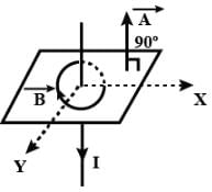
In the arrangement shown in given figure current from A to B is increasing in magnitude. Induced current in the loop will
- a)have clockwise direction
- b)have anticlockwise direction
- c)be zero
- d)oscillate between clockwise and anticlockwise
Correct answer is option 'A'. Can you explain this answer?
In the arrangement shown in given figure current from A to B is increasing in magnitude. Induced current in the loop will
a)
have clockwise direction
b)
have anticlockwise direction
c)
be zero
d)
oscillate between clockwise and anticlockwise

|
New Words answered |
The direction of the induced current is as shown in the figure, according to Lenz’s law which states that the indeed current flows always in such a direction as to oppose the change which is giving rise to it.

A conducting square loop of side I and resistance R moves in its plane with a uniform velocity v perpendicular to one of its sides. A uniform and constant magnetic field B exists along the perpendicular to the plane of the loop in fig. The current induced in the loop is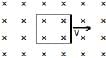
- a)RvB
- b)zero
- c)vBL/R
- d)vBL
Correct answer is option 'B'. Can you explain this answer?
A conducting square loop of side I and resistance R moves in its plane with a uniform velocity v perpendicular to one of its sides. A uniform and constant magnetic field B exists along the perpendicular to the plane of the loop in fig. The current induced in the loop is
a)
RvB
b)
zero
c)
vBL/R
d)
vBL

|
Sivappriya answered |
As the coil is neither moving inside the magnetic flux nor moving outside the magnetic flux the change is magnetic fulx is zero . therefore emf is zero hencecurrent induced in the coil is zero the thing is the coil moves in region of constant and uniform magnetic field ,so as said above current induced is zero option 2 is correct.
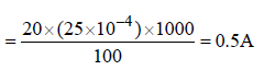
A circular coil of area 200 cm2 and 25 turns rotates about its vertical diameter with an angular speed of 20 ms-1 in a uniform horizontal magnetic field of magnitude 0.05 T. The maximum voltage induced in the coil is- a)0.5 V
- b)1.5 V
- c)2.5 V
- d)2.0 V
Correct answer is option 'A'. Can you explain this answer?
A circular coil of area 200 cm2 and 25 turns rotates about its vertical diameter with an angular speed of 20 ms-1 in a uniform horizontal magnetic field of magnitude 0.05 T. The maximum voltage induced in the coil is
a)
0.5 V
b)
1.5 V
c)
2.5 V
d)
2.0 V
|
|
Hansa Sharma answered |
It is induced EMF of periodic EMI, So formula is:
E= NBAw
Here w is angular speed.
E= NBAw
Here w is angular speed.
So, E = 25×0.05×200×20/10000 =0.5V
Eddy currents have negative effects. Because they produce- a)Harmful radiation
- b)Heating and damping
- c)Damping only
- d)Heating only
Correct answer is option 'B'. Can you explain this answer?
Eddy currents have negative effects. Because they produce
a)
Harmful radiation
b)
Heating and damping
c)
Damping only
d)
Heating only

|
Mamali . answered |
When a conductive material is subjected to a time-varying magnetic flux, eddy currents are generated in the conductor. These eddy currents circulate inside the con- ductor generating a magnetic field of opposite polarity as the applied magnetic field. The interaction of the two magnetic fields causes a force that resists the change in magnetic flux. However, due to the internal resistance of the conductive material, the eddy currents will be dissipated into heat and the force will die out. As the eddy currents are dissipated, energy is removed from the system, thus producing a damp- ing effect.
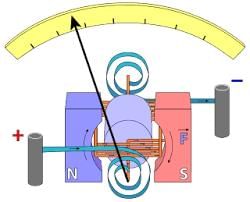
In the dead beat galvanometer, the coil is wound on a frame made of:- a)good conductor
- b)non magnetic material
- c)bad conductor
- d)magnetic material
Correct answer is option 'A'. Can you explain this answer?
In the dead beat galvanometer, the coil is wound on a frame made of:
a)
good conductor
b)
non magnetic material
c)
bad conductor
d)
magnetic material
|
|
Nikita Singh answered |
Aluminum is used as a coil which is a good conductor.
Dead beat galvanometer:
Dead beat galvanometer:
A long metal bar of 30 cm length is aligned along a north south line and moves eastward at a speed of 10 ms-1. A uniform magnetic field of 4.0 T points vertically downwards. If the south end of the bar has a potential of 0V, the induced potential at the north end of the bar is- a) + 12 V
- b)-12 V
- c)0 V
- d)Cannot be determined since there is not closed circuit
Correct answer is option 'A'. Can you explain this answer?
A long metal bar of 30 cm length is aligned along a north south line and moves eastward at a speed of 10 ms-1. A uniform magnetic field of 4.0 T points vertically downwards. If the south end of the bar has a potential of 0V, the induced potential at the north end of the bar is
a)
+ 12 V
b)
-12 V
c)
0 V
d)
Cannot be determined since there is not closed circuit
|
|
Anjali Sharma answered |
Induced emf =Blv=12V. It is induced in the northward direction by right hand rule (emf= )
)
therefore if the south end of the pole has potential of 0V, the north end will have a potential of 12V.
)therefore if the south end of the pole has potential of 0V, the north end will have a potential of 12V.
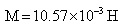
Suppose there are two coils of length 1m with 100 and 200 turns and area of cross section of 5 x 10⁻³ m2. Find the mutual inductance.- a)
- b)
- c)
- d)
Correct answer is option 'C'. Can you explain this answer?
Suppose there are two coils of length 1m with 100 and 200 turns and area of cross section of 5 x 10⁻³ m2. Find the mutual inductance.
a)
b)
c)
d)
|
|
Om Desai answered |
The magnetic field through the secondary of N2 turns of each other of area S is given as,
N2= Φ2=N2(BS)
=μ0n1N2i1S
M= N2Φ2/i1
M= μ0n1N2S
Substituting the values.
M=(4πx10-7) x100x200x5x10-3
=1287142.86x10-10
=12.57x10⁻⁵H
N2= Φ2=N2(BS)
=μ0n1N2i1S
M= N2Φ2/i1
M= μ0n1N2S
Substituting the values.
M=(4πx10-7) x100x200x5x10-3
=1287142.86x10-10
=12.57x10⁻⁵H
The unit of self inductance of a coil is- a)volt s A-1
- b)volt-1s-1 A-1
- c)volt s-1 A-1
- d)volt s-1 A
Correct answer is option 'A'. Can you explain this answer?
The unit of self inductance of a coil is
a)
volt s A-1
b)
volt-1s-1 A-1
c)
volt s-1 A-1
d)
volt s-1 A

|
Infinity Academy answered |
Now, e=L(di/dt)
L=e/(di/dt)
1 henry=1 volt/(1 ampere/second)
L=e/(di/dt)
1 henry=1 volt/(1 ampere/second)
A square coil ABCD is placed in x-y plane with its centre at origin. A long straight wire, passing through origin, carries a current in negative z-direction. Current in this wire increases with time.The induced current in the coil is
- a)clockwise
- b)anticlockwise
- c)zero
- d)alternating
Correct answer is option 'C'. Can you explain this answer?
A square coil ABCD is placed in x-y plane with its centre at origin. A long straight wire, passing through origin, carries a current in negative z-direction. Current in this wire increases with time.The induced current in the coil is
a)
clockwise
b)
anticlockwise
c)
zero
d)
alternating
|
|
Geetika Shah answered |
As magnetic field lines due to current carrying wire is along the surface and hence,
ϕ=B.A=BAcos90O=0
ϕ=B.A=BAcos90O=0
A conducting loop of radius R is present in a uniform magnetic field B perpendicular the plane of the ring. If radius R varies as a function of time `t', as R = R0 + t. The e.m.f induced in the loop is
a)2p (R0 + t) B clockwiseb)p(R0 + t)B clockwisec)2p(R0 + t)B anticlockwised)zeroCorrect answer is option 'C'. Can you explain this answer?
|
|
Lavanya Menon answered |
ε=− dϕ/dt
=−β(dA/dt)
=−β(dA/dt)
⇒∣ε∣=βπd(R0+t)2
=2πβ(R0+t)
Since inward flux is increasing the EMF will be induced counter clockwise.
=2πβ(R0+t)
Since inward flux is increasing the EMF will be induced counter clockwise.
If the current in primary coil changes from 5 A to 2 A in 0.03 sec and the induced e.m.f. is 1000 volts, find the mutual induction- a)0.1 H
- b)0.01 H
- c)10 H
- d)1 H
Correct answer is option 'C'. Can you explain this answer?
If the current in primary coil changes from 5 A to 2 A in 0.03 sec and the induced e.m.f. is 1000 volts, find the mutual induction
a)
0.1 H
b)
0.01 H
c)
10 H
d)
1 H
|
|
Lavanya Menon answered |
As φ =mi
now take change in flux
dφ/dt=d(mi)/dt
we can write it as
dφ/ dt= m Δi/Δt
-e=m(2-5)/0.03
e=3m/0.03
1000=300m/3
m=10
now take change in flux
dφ/dt=d(mi)/dt
we can write it as
dφ/ dt= m Δi/Δt
-e=m(2-5)/0.03
e=3m/0.03
1000=300m/3
m=10
The factor, on which the frequency of an AC generator depends,- a)Material of generator
- b)Speed of rotation
- c)Area of coil
- d)Number of turns in coil
Correct answer is option 'B'. Can you explain this answer?
The factor, on which the frequency of an AC generator depends,
a)
Material of generator
b)
Speed of rotation
c)
Area of coil
d)
Number of turns in coil
|
|
Riya Banerjee answered |
The answer provided in the forum is wrong, the correct answer would be option B and D both.
Solution:
Frequency of a.c, ν=w/2π, where w is the speed of rotation
Also, frequency is defined as the number of rotations that a coil rotates in one second.
Solution:
Frequency of a.c, ν=w/2π, where w is the speed of rotation
Also, frequency is defined as the number of rotations that a coil rotates in one second.
Which of the following will not increase the size and effect of eddy current?- a)Low resistivity materials
- b)Strong magnetic field
- c)Thicker material
- d)Thinner material
Correct answer is option 'D'. Can you explain this answer?
Which of the following will not increase the size and effect of eddy current?
a)
Low resistivity materials
b)
Strong magnetic field
c)
Thicker material
d)
Thinner material
|
|
Hansa Sharma answered |
Stronger magnetic field, thicker material and low resistivity material will increase the size and effect of eddy current whereas thinner material will reduce the effect of eddy currents.
Which of the following quantities can be written in SI units in K gm2 A-2 S-3 ?- a)Resistance
- b)Inductance
- c)Capacitance
- d)Magnetic flux
Correct answer is option 'A'. Can you explain this answer?
Which of the following quantities can be written in SI units in K gm2 A-2 S-3 ?
a)
Resistance
b)
Inductance
c)
Capacitance
d)
Magnetic flux
|
|
Nikita Singh answered |
The dimensional formula of a given unit is [ML2T−3A−2].
So, from the given option only resistance has this dimensional formula so resistance is the correct answer.
So, from the given option only resistance has this dimensional formula so resistance is the correct answer.
The mutual induction does not depend on which of the following factors- a)Number of turns
- b)Shape of the two coils
- c)Distance between two coils
- d)Current through both the coils
Correct answer is option 'D'. Can you explain this answer?
The mutual induction does not depend on which of the following factors
a)
Number of turns
b)
Shape of the two coils
c)
Distance between two coils
d)
Current through both the coils
|
|
Rajat Patel answered |
The factors which determine the value of mutual inductance are —
a. number of turns of the coils
b. separation of coils
c. geometric shape and size of coils
d. angular orientation between the coils
Two infinitely long conducting parallel rails are connected through a capacitor C as shown in the figure. A conductor of length l is moved with constant speed v0. Which of the following graph truly depicts the variation of current through the conductor with time ?
- a)
- b)
- c)

- d)

Correct answer is option 'C'. Can you explain this answer?
Two infinitely long conducting parallel rails are connected through a capacitor C as shown in the figure. A conductor of length l is moved with constant speed v0. Which of the following graph truly depicts the variation of current through the conductor with time ?
a)
b)
c)
d)
|
|
Anaya Patel answered |
By Faraday's Law of induction,
ε=− dϕ/dt
=−Bl (dx/dt) =−Blv0
This emf should induce the movement of charges creating a current. But due to the attached capacitor, all charges are conserved.
Thus I= dq/dt =0
The correct option is C.
ε=− dϕ/dt
=−Bl (dx/dt) =−Blv0
This emf should induce the movement of charges creating a current. But due to the attached capacitor, all charges are conserved.
Thus I= dq/dt =0
The correct option is C.
Identify the type of commercial motor which works as a consequence of eddy currents.- a)Compressors
- b)Induction motors
- c)Turbines
- d)Hydropowered motors
Correct answer is option 'B'. Can you explain this answer?
Identify the type of commercial motor which works as a consequence of eddy currents.
a)
Compressors
b)
Induction motors
c)
Turbines
d)
Hydropowered motors
|
|
Varun Kapoor answered |
A rotating magnetic field is produced employing two single-phase currents. A metallic rotor placed inside the rotating magnetic field starts rotating due to large eddy currents produced in it. These motors are commonly used in fans.
Eddy currents do not cause:- a)sparking
- b)heating
- c)loss of energy
- d)damping
Correct answer is option 'A'. Can you explain this answer?
Eddy currents do not cause:
a)
sparking
b)
heating
c)
loss of energy
d)
damping
|
|
Arjun Singhania answered |
During braking, the metal wheels are exposed to a magnetic field from an electromagnet, generating eddy currents in the wheels. So, by Lenz's law, the magnetic field formed by the Eddy current will oppose its cause. Thus the wheel will face a force opposing the initial movement of the wheel.
Whenever the magnetic flux ( ) linked with a coil changes the emf is induced in the circuit, This emf lasts
- a)as long as the change in flux continues.
- b)for a long time
- c)for a short time
- d)forever
Correct answer is option 'A'. Can you explain this answer?
Whenever the magnetic flux () linked with a coil changes the emf is induced in the circuit, This emf lasts
) linked with a coil changes the emf is induced in the circuit, This emf lastsa)
as long as the change in flux continues.
b)
for a long time
c)
for a short time
d)
forever

|
Idamangala Merlin answered |
Answer a it is faraday 1st law
A magnet is moved towards the coil (a) quickly and (b) slowly, and then the work done is- a)does not depend on the motion of the magnet.
- b)smaller in case (a)
- c)equal in both cases
- d)larger in case (a)
Correct answer is option 'D'. Can you explain this answer?
A magnet is moved towards the coil (a) quickly and (b) slowly, and then the work done is
a)
does not depend on the motion of the magnet.
b)
smaller in case (a)
c)
equal in both cases
d)
larger in case (a)
|
|
Jayant Mishra answered |
A magnet is moved towards the coil (a) quickly and (b) slowly, and then the work done is This is because when the magnet is moved quickly, opposing emf induced in the coil will be more.
In which of the following cases with a bar magnet and the coil no induced emf is induced.- a)When there is no relative motion between the magnet and the coil.
- b)When the coil is moved towards or away from the magnet.
- c)When the magnet is taken away from the coil.
- d)When the magnet is inserted into the coil.
Correct answer is option 'A'. Can you explain this answer?
In which of the following cases with a bar magnet and the coil no induced emf is induced.
a)
When there is no relative motion between the magnet and the coil.
b)
When the coil is moved towards or away from the magnet.
c)
When the magnet is taken away from the coil.
d)
When the magnet is inserted into the coil.
|
|
Lavanya Menon answered |
This is because induced emf directly depends on relative motion between the magnet and coil, but if there is no relative motion between them, there will be no emf induced.
A conducting wire frame is placed in a magnetic field which is directed into the paper. The magnetic field is increasing at a constant rate. The directions of induced currents in wires AB and CD are 
- a) B to A and D to C
- b)A to B and C to D
- c)A to B and D to C
- d)B to A and C to D
Correct answer is option 'A'. Can you explain this answer?
A conducting wire frame is placed in a magnetic field which is directed into the paper. The magnetic field is increasing at a constant rate. The directions of induced currents in wires AB and CD are
a)
B to A and D to C
b)
A to B and C to D
c)
A to B and D to C
d)
B to A and C to D
|
|
Preeti Khanna answered |
Consider the surface facing upwards having points A, B, C and D in anticlockwise direction when viewing towards the surface from above. Let this be S
flux = S×B
As the flux increases, by Lenz's Law the induced current will be in the direction C B A D C, so as to oppose the increase in flux.
flux = S×B
As the flux increases, by Lenz's Law the induced current will be in the direction C B A D C, so as to oppose the increase in flux.
Two pure inductors are connected in series, if their self inductance is L. Find the total inductance- a)0.5L
- b)L
- c)2L
- d)0.2L
Correct answer is option 'C'. Can you explain this answer?
Two pure inductors are connected in series, if their self inductance is L. Find the total inductance
a)
0.5L
b)
L
c)
2L
d)
0.2L

|
Sidharth Gupta answered |
Its same as in resistor series formula
The role of inductance is equivalent to:- a)energy
- b)force
- c)inertia
- d)momentum
Correct answer is option 'C'. Can you explain this answer?
The role of inductance is equivalent to:
a)
energy
b)
force
c)
inertia
d)
momentum
|
|
Rahul Bansal answered |
Self induction is that phenomenon in which a change in electric current in a coil produces an induced emf in the coil itself.
Now, it is also known as inertia of electricity as for if we were to change electric current through a current carrying coil it will tend to oppose any further change in its emf. This is similar to inertial behavior in mechanics where bodies in either rest or motion tend to oppose any change in their state. Here mass is the inertial property analogous to self inductance.
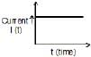
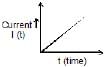
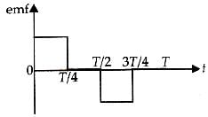
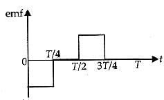
The current i in a coil varies with time as shown in the figure. The variation of induced emf with time would be [2011]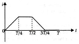
- a)

- b)
- c)
- d)
Correct answer is option 'A'. Can you explain this answer?
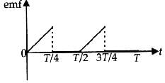
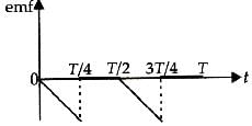
The current i in a coil varies with time as shown in the figure. The variation of induced emf with time would be [2011]
a)
b)
c)
d)
|
|
Krishna Iyer answered |
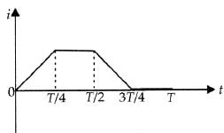
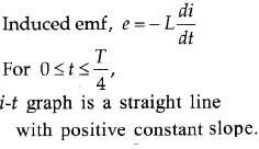
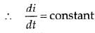
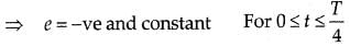
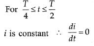

i-t graph is a straight line with negative constant slope.
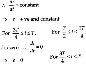
From this analysis, the variation of induced emf with time as shown in the figure below.
Two identical conductors P and Q are placed on two frictionless fixed conducting rails R and S in a uniform magnetic field directed into the plane. If P is moved in the direction shown in figure with a constant speed, then rod Q
- a)will be attracted towards P
- b)will be repelled away from P
- c)will remain stationary
- d)may be repelled or attracted towards P
Correct answer is option 'A'. Can you explain this answer?
Two identical conductors P and Q are placed on two frictionless fixed conducting rails R and S in a uniform magnetic field directed into the plane. If P is moved in the direction shown in figure with a constant speed, then rod Q
a)
will be attracted towards P
b)
will be repelled away from P
c)
will remain stationary
d)
may be repelled or attracted towards P
|
|
Neha Sharma answered |
As the conductor P moves away from Q, the area of the loop enclosed by the conductors and the rails increases. This in turn increases the flux through the loop.
EMF will be induced in such a way that the change in flux will be resisted. The induced current will cause Q to move towards P thereby reducing the area and thus the flux back.
EMF will be induced in such a way that the change in flux will be resisted. The induced current will cause Q to move towards P thereby reducing the area and thus the flux back.
A small conducting rod of length l, moves with a uniform velocity v in a uniform magnetic field B as shown in fig-
- a)Then the end X of the rod becomes positively charged
- b)the end Y of the rod becomes positively charged
- c)the entire rod is unevely charged
- d)the rod becomes hot due to joule heating
Correct answer is option 'B'. Can you explain this answer?
A small conducting rod of length l, moves with a uniform velocity v in a uniform magnetic field B as shown in fig-
a)
Then the end X of the rod becomes positively charged
b)
the end Y of the rod becomes positively charged
c)
the entire rod is unevely charged
d)
the rod becomes hot due to joule heating

|
Dr Manju Sen answered |
The rod is moving towards the right in a field directed into the page.
Now, if we apply Fleming's right hand rule, then the direction of induced current will be from end X to end Y.
But, according to Lenz's law the emf induced in the rod will be such that it opposes the motion of the rod.
Hence, the actual emf induced will be from end Y to end X. So, the current will also flow from end Y to end X.
Now, using the convention of current end Y should be positive and end X should be negative.
So, correct answer is option b
The instantaneous flux associated with a closed circuit of 10Ω resistance is indicated by the following reaction f = 6t2 _ 5t + 1, then the value in amperes of the induced current at t = 0.25 sec will be- a)1.2
- b)0.8
- c)6
- d)0.2
Correct answer is option 'D'. Can you explain this answer?
The instantaneous flux associated with a closed circuit of 10Ω resistance is indicated by the following reaction f = 6t2 _ 5t + 1, then the value in amperes of the induced current at t = 0.25 sec will be
a)
1.2
b)
0.8
c)
6
d)
0.2
|
|
Vivek Rana answered |
ϕ=6t2−5t+1
e= dϕ/dt =12t−5
at t=0.25sec
∣e∣=(12/4−5)=∣3−5∣=2
i=e/R=2/10=0.2A
e= dϕ/dt =12t−5
at t=0.25sec
∣e∣=(12/4−5)=∣3−5∣=2
i=e/R=2/10=0.2A
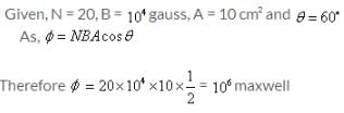
A coil of area 10 cm² of 20 turns is placed in uniform magnetic field of 104 gauss. The normal to the plane of the coil makes an angle of 60° with the magnetic field. The flux in maxwell through the coil is
- a)105
- b)106
- c)103
- d)104
Correct answer is option 'B'. Can you explain this answer?
A coil of area 10 cm² of 20 turns is placed in uniform magnetic field of 104 gauss. The normal to the plane of the coil makes an angle of 60° with the magnetic field. The flux in maxwell through the coil is
a)
105
b)
106
c)
103
d)
104
|
|
Hansa Sharma answered |
The number of turns in a long solenoid is 500. The area of cross-section of solenoid is 2 × 10⁻³ m2. If the value of magnetic induction, on passing a current of 2 amp, through it is 5 × 10⁻³ tesla, the magnitude of magnetic flux connected with it in webers will be- a)5 × 10⁻³
- b)10-2
- c)10-5
- d)2.5
Correct answer is option 'A'. Can you explain this answer?
The number of turns in a long solenoid is 500. The area of cross-section of solenoid is 2 × 10⁻³ m2. If the value of magnetic induction, on passing a current of 2 amp, through it is 5 × 10⁻³ tesla, the magnitude of magnetic flux connected with it in webers will be
a)
5 × 10⁻³
b)
10-2
c)
10-5
d)
2.5
|
|
Preeti Iyer answered |
Φ=BAN
=5x10-3x2x10-3x500
=5x10-3x1000x10-3
=5x10-3
=5x10-3x2x10-3x500
=5x10-3x1000x10-3
=5x10⁻³
The no-load current drawn by transformer is usually what per cent of the full-load current ?- a)0.2 to 0.5 per cent
- b)2 to 5 per cent
- c)12 to 15 per cent
- d)20 to 30 per cent
Correct answer is option 'B'. Can you explain this answer?
The no-load current drawn by transformer is usually what per cent of the full-load current ?
a)
0.2 to 0.5 per cent
b)
2 to 5 per cent
c)
12 to 15 per cent
d)
20 to 30 per cent

|
Baishali Chakraborty answered |
The no load current is about 2-5% of the full load current and it accounts for the losses in a transformer. These no-load losses include core(iron/fixed) losses, which contains eddy current losses & hysteresis losses and the copper(I2*R) losses due to the no Load current.
Eddy currents can be induced in- a)Metal Blocks
- b)Wires
- c)Both metal blocks and wires
- d)Insulators
Correct answer is option 'C'. Can you explain this answer?
Eddy currents can be induced in
a)
Metal Blocks
b)
Wires
c)
Both metal blocks and wires
d)
Insulators

|
Anusaya Swain answered |
Eddy currents are produced by varying magnetic field in solid plates, blocks and wires.
Find the dimension of the quantity  , where symbols have usual meaning.
- a)A-1
- b)A-2
- c)A
- d)A2
Correct answer is option 'A'. Can you explain this answer?
Find the dimension of the quantity , where symbols have usual meaning.
, where symbols have usual meaning.a)
A-1
b)
A-2
c)
A
d)
A2
|
|
Harsh Singhal answered |
On multiply w in upper & lower side we get inductive reactance & capacitive reactance
so on cancel out in term of unit we get R/V
which is equal to 1/i= A-1
so on cancel out in term of unit we get R/V
which is equal to 1/i= A-1
An air-cored solenoid with length 30 cm, area of cross-section 25 cm2 and number of turns 500, carries a current of 2.5 A. The current is suddenly switched off in a brief time of 10−3s. Average back emf induced across the ends of the open switch in the circuit is- a)6.5 V .
- b)4.6 V
- c)4.5 V
- d)5 V3.
Correct answer is option 'A'. Can you explain this answer?
An air-cored solenoid with length 30 cm, area of cross-section 25 cm2 and number of turns 500, carries a current of 2.5 A. The current is suddenly switched off in a brief time of 10−3s. Average back emf induced across the ends of the open switch in the circuit is
a)
6.5 V .
b)
4.6 V
c)
4.5 V
d)
5 V3.
|
|
Arka Das answered |
-4 seconds. Find the average induced emf in the solenoid during this time.
We can use Faraday's law of induction to find the average induced emf in the solenoid:
emf = -N (ΔΦ/Δt)
where N is the number of turns, ΔΦ is the change in magnetic flux, and Δt is the time interval.
Since the current is suddenly switched off, the magnetic flux through the solenoid changes from its maximum value to zero. The maximum value of magnetic flux through the solenoid is given by:
Φ = B A
where B is the magnetic field strength and A is the area of cross-section. Since the solenoid is air-cored, the magnetic field is given by:
B = μ0 N I / L
where μ0 is the permeability of free space, I is the current, and L is the length of the solenoid. Substituting the given values, we get:
B = (4π × 10^-7) × 500 × 2.5 / 0.3 = 1.05 T
Therefore, the maximum magnetic flux through the solenoid is:
Φ = 1.05 × 25 × 10^-4 = 2.625 × 10^-5 Wb
During the brief time of 10^-4 seconds, the change in magnetic flux is equal to the maximum flux, since the current is switched off suddenly. Therefore, ΔΦ = 2.625 × 10^-5 Wb.
Substituting the given values in the formula for emf, we get:
emf = -500 (2.625 × 10^-5) / (10^-4) = -1.3125 V
Therefore, the average induced emf in the solenoid during the brief time of 10^-4 seconds is 1.3125 V. Note that the negative sign indicates that the induced emf opposes the change in current.
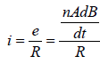
A rectangular coil of 20 turns and area of crosssection 25 sq. cm has a resistance of 100Ω. If amagnetic field which is perpendicular to the planeof coil changes at a rate of 1000 tesla per second,the current in the coil is [1992]- a)1 A
- b)50 A
- c)0.5 A
- d)5 A
Correct answer is option 'C'. Can you explain this answer?
A rectangular coil of 20 turns and area of crosssection 25 sq. cm has a resistance of 100Ω. If amagnetic field which is perpendicular to the planeof coil changes at a rate of 1000 tesla per second,the current in the coil is [1992]
a)
1 A
b)
50 A
c)
0.5 A
d)
5 A

|
Abhishek Desai answered |
When a wire loop is rotated in a magnetic field, the direction of induced emf changes once in each- a)2 revolutions
- b)1 revolution
- c)1/2 revolution
- d)12 revolution
Correct answer is option 'C'. Can you explain this answer?
When a wire loop is rotated in a magnetic field, the direction of induced emf changes once in each
a)
2 revolutions
b)
1 revolution
c)
1/2 revolution
d)
12 revolution
|
|
Rajeev Saxena answered |
Flux of the magnetic field through the loop is ϕ=Bπr2coswt
Where θ= angle the normal makes with the portion of the loop in duced emf.
∈=wBπr2sinwt
These is zero when wt=nπ ie
When θ=0,π,2π.... etc.
So, the induced emf changes direction every half rotation.
Inductance is a _______ quantity. Its dimension is ________.- a)scalar, [ML2T-2 A-2]
- b)scalar, [MLT-2 A-2]
- c)vector, [ML2T-2 A-2]
- d)scalar, [ML2T2 A-2]
Correct answer is option 'A'. Can you explain this answer?
Inductance is a _______ quantity. Its dimension is ________.
a)
scalar, [ML2T-2 A-2]
b)
scalar, [MLT-2 A-2]
c)
vector, [ML2T-2 A-2]
d)
scalar, [ML2T2 A-2]
|
|
Preeti Iyer answered |
It is also called the Coefficient of induction. Coefficient of induction is about the ratio of current induced with respect to magnetic flux. This constant of proportionality is known as Inductance. It is a scalar quantity.
The dimension of inductance- M1·L2·T−2·A−2
The dimension of inductance- M1·L2·T−2·A−2
The dimensions of permeability of free space can be given by- a)[MLT-2A-2]
- b)[MLA-2]
- c)[ML-3T2A2]
- d)[MLA-1]
Correct answer is option 'A'. Can you explain this answer?
The dimensions of permeability of free space can be given by
a)
[MLT-2A-2]
b)
[MLA-2]
c)
[ML-3T2A2]
d)
[MLA-1]
|
|
Lavanya Menon answered |
In SI units, permeability is measured in Henries per meter H/m or Hm−1.
Henry has the dimensions of [ML2T−2A−2].
Dimensions for magnetic permeability will be [ML2T−2A−2]/[L]=[MLT−2A−2]
Henry has the dimensions of [ML2T−2A−2].
Dimensions for magnetic permeability will be [ML2T−2A−2]/[L]=[MLT−2A−2]
In an iron cored coil the iron core is removed so that the coil becomes an air cored coil. The inductance of the coil will- a)increase
- b)decrease
- c)remain the same
- d)initially increase and then decrease
Correct answer is option 'B'. Can you explain this answer?
In an iron cored coil the iron core is removed so that the coil becomes an air cored coil. The inductance of the coil will
a)
increase
b)
decrease
c)
remain the same
d)
initially increase and then decrease
|
|
Nandini Iyer answered |
In an iron cored coil the iron core is removed so that the coil becomes an air cored coil. The inductance of the coil will decrease.
In electromagnetic induction, line integral of induced field E around a close path is __________, induced electric field is ___________.- a)Zero, Non Conservative
- b)Non zero, Conservative
- c)Zero, Conservative
- d)Non zero, Non Conservative
Correct answer is option 'D'. Can you explain this answer?
In electromagnetic induction, line integral of induced field E around a close path is __________, induced electric field is ___________.
a)
Zero, Non Conservative
b)
Non zero, Conservative
c)
Zero, Conservative
d)
Non zero, Non Conservative
|
|
Kalyan Chavan answered |
In electromagnetic induction, line integral of induced field E around a close path is non zero, and induced electric field is non conservative.
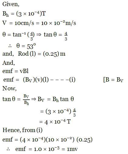
The horizontal component of the earth's magnetic field at a place is 3 × 10⁻⁴ T and the dip is tan-1(4/3). A metal rod of length 0.25 m placed in the north-south position is moved at a constant speed of 10 cm/s towards the east. Find the e.m.f induced in the rod. in mV
Correct answer is '1'. Can you explain this answer?
The horizontal component of the earth's magnetic field at a place is 3 × 10⁻⁴ T and the dip is tan-1(4/3). A metal rod of length 0.25 m placed in the north-south position is moved at a constant speed of 10 cm/s towards the east. Find the e.m.f induced in the rod. in mV

|
Manish Aggarwal answered |
AB and CD are smooth parallel rails, separated by a distance l, and inclined to the horizontal at an angle q. A uniform magnetic field of magnitude B, directed vertically upwards, exists in the region. EF is a conductor of mass m, carrying a current i. if B is normal to the plane of the rails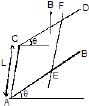
- a)Bil = mg tan q
- b)Bil = mg sin q
- c)Bil = mg cos q
- d)Equilibrium cannot be reached
Correct answer is option 'B'. Can you explain this answer?
AB and CD are smooth parallel rails, separated by a distance l, and inclined to the horizontal at an angle q. A uniform magnetic field of magnitude B, directed vertically upwards, exists in the region. EF is a conductor of mass m, carrying a current i. if B is normal to the plane of the rails
a)
Bil = mg tan q
b)
Bil = mg sin q
c)
Bil = mg cos q
d)
Equilibrium cannot be reached
|
|
Om Desai answered |
As seen from the image, in the direction of magnetic field
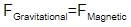
mgsinθ=il×B
mgsinθ=ilB
mgsinθ=il×B
mgsinθ=ilB
two different arrangements in which two square wire frames of same resistance are placed in a uniform constantly decreasing magnetic field B. 
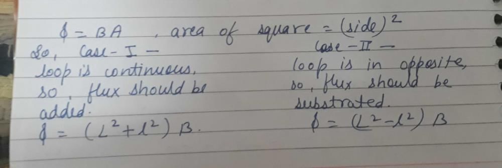
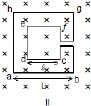 The value of magnetic flux in each case is given by
- a) Case I : f = p(L2 + ℓ2 ) B; Case II : f = p(L2 – ℓ2) B
- b)Case I : f = p(L2 + ℓ2) B; Case II : f = p(L2 + ℓ2) B
- c)Case I : f = (L2 + ℓ2) B; Case II : f = (L2 – ℓ2) B
- d)Case I : f = (L + ℓ)2 B; Case II : f = (L – ℓ)2 B
Correct answer is option 'C'. Can you explain this answer?
two different arrangements in which two square wire frames of same resistance are placed in a uniform constantly decreasing magnetic field B.
The value of magnetic flux in each case is given by
a)
Case I : f = p(L2 + ℓ2 ) B; Case II : f = p(L2 – ℓ2) B
b)
Case I : f = p(L2 + ℓ2) B; Case II : f = p(L2 + ℓ2) B
c)
Case I : f = (L2 + ℓ2) B; Case II : f = (L2 – ℓ2) B
d)
Case I : f = (L + ℓ)2 B; Case II : f = (L – ℓ)2 B
|
|
Himanshu Jhajharia answered |
A circular coil of radius 8.0 cm and 20 turns is rotated about its vertical diameter with an angular speed of 50 rad s-1 in a uniform horizontal magnetic field of magnitude 3×10⁻² T. If the coil resistance is 10Ω, maximum emf induced in the coil,maximum value of current in the coil and average power loss due to Joule heating are- a)0.603 V, 0.0303 A,0.018 W
- b)0.603 V, 0.0603 A,0.038 W
- c)0.603 V, 0.0603 A,0.018 W .
- d)0.303 V, 0.0603 A,0.018 W
Correct answer is option 'C'. Can you explain this answer?
A circular coil of radius 8.0 cm and 20 turns is rotated about its vertical diameter with an angular speed of 50 rad s-1 in a uniform horizontal magnetic field of magnitude 3×10⁻² T. If the coil resistance is 10Ω, maximum emf induced in the coil,maximum value of current in the coil and average power loss due to Joule heating are
a)
0.603 V, 0.0303 A,0.018 W
b)
0.603 V, 0.0603 A,0.038 W
c)
0.603 V, 0.0603 A,0.018 W .
d)
0.303 V, 0.0603 A,0.018 W

|
Bhavana Banerjee answered |
e = NBAω = 20 x 3 x 10-2 x (3.14 x 0.08 x 0.08) x 50 = 0.603C

average power loss due to joule heating


The principle of electromagnetic induction is used in which of the following phenomenon- a)Generation of electricity in hydroelectricity.
- b)Generation of electricity in nuclear power plant.
- c)Generation of electricity in thermal power plant.
- d)Generation of electricity from wind energy.
Correct answer is option 'A'. Can you explain this answer?
The principle of electromagnetic induction is used in which of the following phenomenon
a)
Generation of electricity in hydroelectricity.
b)
Generation of electricity in nuclear power plant.
c)
Generation of electricity in thermal power plant.
d)
Generation of electricity from wind energy.
|
|
Animesh Nhagal answered |
Electrical generators (such as hydroelectric dams) where mechanical power is used to move a magnetic field past coils of wire to generate voltage
Chapter doubts & questions for Electromagnetic Induction - Topic-wise MCQ Tests for NEET 2025 is part of NEET exam preparation. The chapters have been prepared according to the NEET exam syllabus. The Chapter doubts & questions, notes, tests & MCQs are made for NEET 2025 Exam. Find important definitions, questions, notes, meanings, examples, exercises, MCQs and online tests here.
Chapter doubts & questions of Electromagnetic Induction - Topic-wise MCQ Tests for NEET in English & Hindi are available as part of NEET exam.
Download more important topics, notes, lectures and mock test series for NEET Exam by signing up for free.
Topic-wise MCQ Tests for NEET
9 docs|806 tests
|
|
© EduRev
|
Education Revolution
|


|


Signup to see your scores
go up
within 7 days!
within 7 days!
Takes less than 10 seconds to signup