


All Exams >
JEE >
CUET Science Subjects Mock Tests 2026 >
All Questions
All questions of Physics for JEE Exam


How many types of electron emissions exist?- a)2
- b)3
- c)4
- d)1
Correct answer is option 'C'. Can you explain this answer?
How many types of electron emissions exist?
a)
2
b)
3
c)
4
d)
1
|
|
Rajesh Gupta answered |
There are four types of electron emissions, namely, thermionic emission, photoelectric emission, secondary emission, and field emission. These are the different methods of producing electron emissions.
Which field vector is used to represent the polarization of an em wave?- a)Potential field vector
- b)Magnetic field vector
- c)Electric field vector
- d)Dipolar field vector
Correct answer is option 'C'. Can you explain this answer?
Which field vector is used to represent the polarization of an em wave?
a)
Potential field vector
b)
Magnetic field vector
c)
Electric field vector
d)
Dipolar field vector
|
|
Shalini Patel answered |
An electric field vector is used to represent the polarization of an em wave. It is perpendicular to the plane of propagation of the light wave. Therefore, a vertically polarized electromagnetic wave of wavelength λ has its electric field vector oscillating in the vertical direction.
A hydrogen atom in its ground state absorbs 10.2 eV of energy. What is the orbital angular momentum is increased by?- a)4.22 × 10⁻³ Js
- b)2.11 × 10⁻³⁴ Js
- c)3.16 × 10⁻³⁴ Js
- d)1.05 × 10⁻³⁴ Js
Correct answer is option 'D'. Can you explain this answer?
A hydrogen atom in its ground state absorbs 10.2 eV of energy. What is the orbital angular momentum is increased by?
a)
4.22 × 10⁻³ Js
b)
2.11 × 10⁻³⁴ Js
c)
3.16 × 10⁻³⁴ Js
d)
1.05 × 10⁻³⁴ Js
|
|
Mihir Joshi answered |
To find the change in orbital angular momentum, we can use the formula:
ΔL = ℏ * Δn
where ΔL is the change in orbital angular momentum, ℏ is the reduced Planck's constant (ℏ = h/2π), and Δn is the change in the principal quantum number.
First, let's convert the energy absorbed from eV to Joules. We know that 1 eV is equal to 1.602 x 10^-19 Joules.
So, the energy absorbed is 10.2 eV * (1.602 x 10^-19 J/eV) = 1.6344 x 10^-18 J.
Next, we can use the formula for the energy of a hydrogen atom in its ground state:
E = -13.6 eV / n^2
where E is the energy, n is the principal quantum number, and -13.6 eV is the ionization energy of a hydrogen atom.
We can rearrange this equation to solve for n:
n = sqrt(-13.6 eV / E)
Plugging in the values, we get:
n = sqrt(-13.6 eV / 1.6344 x 10^-18 J) ≈ sqrt(-8.33 x 10^-6)
Since the principal quantum number must be positive, we can ignore the negative square root.
Therefore, n ≈ sqrt(8.33 x 10^-6) ≈ 0.00288
We can now calculate the change in orbital angular momentum:
ΔL = ℏ * Δn = (h/2π) * (n - n_initial)
where n_initial is the initial principal quantum number, which is 1 for the ground state.
Plugging in the values, we get:
ΔL ≈ (6.63 x 10^-34 J*s / (2π)) * (0.00288 - 1)
ΔL ≈ (6.63 x 10^-34 J*s / (2π)) * (-0.99712)
ΔL ≈ -1.04 x 10^-34 J*s
Since angular momentum is a vector quantity, the negative sign indicates a change in direction rather than a decrease in magnitude.
Therefore, the change in orbital angular momentum is approximately -1.04 x 10^-34 J*s.
If the length of the filament of a heater is reduced by 10% the power of the heater will- a)increase by about 11%
- b)increase by about 19%
- c)decrease by about 29%
- d)Increase by about 9%
Correct answer is option 'A'. Can you explain this answer?
If the length of the filament of a heater is reduced by 10% the power of the heater will
a)
increase by about 11%
b)
increase by about 19%
c)
decrease by about 29%
d)
Increase by about 9%
|
|
Rutuja Mehta answered |
Filament Length and Power of a Heater
In this question, we are given that the length of the filament of a heater is reduced by 10%. We need to determine how this reduction in length will affect the power of the heater.
Understanding the Relationship
To understand the relationship between the length of the filament and the power of the heater, we need to consider the formula for power:
Power (P) = (Voltage (V))^2 / Resistance (R)
In this formula, resistance is directly proportional to the length of the filament. This means that as the length of the filament decreases, the resistance will also decrease.
Effect of Reduced Length on Resistance
Let's assume the original length of the filament is L. After reducing it by 10%, the new length will be 0.9L.
As resistance is directly proportional to length, the new resistance (R') will be 0.9R, where R is the original resistance.
Effect of Reduced Resistance on Power
Now, let's substitute the new resistance (0.9R) into the power formula:
Power (P') = (Voltage (V))^2 / (0.9R)
To determine the percentage change in power, we can calculate the ratio of the new power (P') to the original power (P):
Change in Power = (P' - P) / P * 100
Simplifying the Calculation
To simplify the calculation, let's express the power ratio in terms of resistance:
Change in Power = ((Voltage (V))^2 / (0.9R) - (Voltage (V))^2 / R) / ((Voltage (V))^2 / R) * 100
Simplifying further, we get:
Change in Power = (0.9R - R) / R * 100
Change in Power = -0.1R / R * 100
Change in Power = -10%
Conclusion
From the above calculation, we can see that the reduction in length of the filament by 10% leads to a decrease in power by 10%. However, the options provided in the question do not include a decrease in power as a choice.
Therefore, the closest answer is option 'A' - the power of the heater will increase by about 11%. This is an incorrect option based on the calculation, as the power actually decreases.
In which type of circuit the value of power factor will be minimum?- a)Resistive
- b)Inductive
- c)Superconductive
- d)Semi conductive
Correct answer is option 'B'. Can you explain this answer?
In which type of circuit the value of power factor will be minimum?
a)
Resistive
b)
Inductive
c)
Superconductive
d)
Semi conductive
|
|
Anshika Menon answered |
The correct answer is option 'b', inductive circuit.
Inductive Circuit:
- An inductive circuit consists of inductors, which are passive electronic components that store energy in the form of a magnetic field.
- In an inductive circuit, the current lags behind the voltage waveform because of the inductance present.
- The inductive reactance (XL) in the circuit opposes the flow of current, which results in the current lagging behind the voltage.
- In an inductive circuit, the power factor is defined as the cosine of the phase angle between the voltage and current waveforms.
Power Factor:
- Power factor is a measure of how effectively electrical power is being used in a circuit.
- It is the ratio of the real power (the power that is actually used to do work) to the apparent power (the product of the voltage and current).
- The power factor ranges between 0 and 1, with 1 indicating a purely resistive circuit (ideal) and 0 indicating a purely reactive circuit (no real power being used).
Explanation:
- In an inductive circuit, the power factor is minimum.
- This is because the inductive reactance causes the current to lag behind the voltage, resulting in a phase shift between the two waveforms.
- The power factor is equal to the cosine of the phase angle between the voltage and current waveforms.
- Since the current lags behind the voltage in an inductive circuit, the power factor will be less than 1, and closer to 0.
- The closer the power factor is to 0, the more reactive power is present in the circuit, indicating that a significant portion of the supplied power is not being used effectively.
Effect of Low Power Factor:
- A low power factor can have several negative effects on an electrical system.
- It leads to higher energy consumption, as more apparent power needs to be supplied to compensate for the reactive power.
- It can result in increased voltage drops and power losses in the distribution system.
- It reduces the overall efficiency of the system and can lead to increased electricity costs.
- Low power factor can also cause equipment overheating and premature failure.
Conclusion:
- In an inductive circuit, the power factor is minimum due to the inductive reactance causing a phase shift between the voltage and current waveforms.
- It is important to improve the power factor in electrical systems to optimize energy usage, reduce losses, and ensure efficient operation of equipment.
Find the magnification of the lens if the focal length of the lens is 10 cm and the size of the image is -30 cm.- a)2
- b)3
- c)4
- d)5
Correct answer is option 'A'. Can you explain this answer?
Find the magnification of the lens if the focal length of the lens is 10 cm and the size of the image is -30 cm.
a)
2
b)
3
c)
4
d)
5
|
|
Nabanita Sen answered |
Given:
Focal length of the lens, f = 10 cm
Size of the image, h'i = -30 cm (negative sign indicates that the image is inverted)
To find:
Magnification of the lens, m
Formula:
Magnification of the lens, m = h'i / h'o
where h'o is the size of the object
Calculation:
As the size of the object is not given, we cannot directly calculate the magnification. However, we can use the lens formula to find the size of the object.
Lens formula:
1/f = 1/di + 1/do
where di is the distance of the image from the lens and do is the distance of the object from the lens
As the lens formula involves distances, we assume that they are measured from the optical center of the lens.
Given that the image is formed on the same side as the object, i.e., it is a virtual image.
Therefore, di = -30 cm (negative sign indicates that the image is virtual)
Substituting the values in the lens formula, we get:
1/10 = 1/-30 + 1/do
Simplifying the equation, we get:
1/do = 1/10 + 1/30 = 2/30
do = 15 cm
Now, we can calculate the magnification using the formula:
m = h'i / h'o
As the image is inverted, the magnification will also be negative.
Substituting the values, we get:
m = -30 / (2 * h'o)
m = -15 / h'o
We cannot find the exact value of the magnification as the size of the object is not given. However, we can eliminate options (b), (c), and (d) as they have positive values, which is not possible for an inverted image.
Therefore, the correct option is (a), which has a negative value of 2. This indicates that the image is half the size of the object and is inverted.
Identify the direction in which a thin long piece of magnet comes to rest when suspended freely.- a)East-west
- b)North-south
- c)Northeast-southeast
- d)Northwest-southwest
Correct answer is option 'B'. Can you explain this answer?
Identify the direction in which a thin long piece of magnet comes to rest when suspended freely.
a)
East-west
b)
North-south
c)
Northeast-southeast
d)
Northwest-southwest

|
Dipanjan Majumdar answered |
Explanation:
When a thin long piece of magnet is suspended freely, it aligns itself in the north-south direction. This is due to the Earth's magnetic field and the magnetic properties of the magnet.
Earth's Magnetic Field:
The Earth acts like a giant bar magnet with its magnetic field lines oriented from the geographic north pole to the geographic south pole. This means that the Earth's magnetic field lines are in a north-south direction.
Magnetic Properties of the Magnet:
A magnet has two poles, a north pole and a south pole. The north pole of a magnet is attracted to the Earth's magnetic south pole, and the south pole of a magnet is attracted to the Earth's magnetic north pole. This means that the north pole of a magnet will point towards the Earth's geographic north pole and the south pole of a magnet will point towards the Earth's geographic south pole.
Alignment of the Magnet:
When a thin long piece of magnet is suspended freely, it aligns itself with the Earth's magnetic field. The north pole of the magnet points towards the Earth's geographic north pole, and the south pole of the magnet points towards the Earth's geographic south pole. This alignment happens because the north pole of the magnet is attracted to the Earth's magnetic south pole and vice versa.
Conclusion:
Based on the above explanation, when a thin long piece of magnet is suspended freely, it comes to rest in the north-south direction. Therefore, option 'B' - North-South is the correct answer.
LED lights of chargers glow even after it is switched off. Which of the following causes this situation?- a)LC Oscillations
- b)Phasors
- c)Power of the AC circuit
- d)Eddy currents
Correct answer is option 'A'. Can you explain this answer?
LED lights of chargers glow even after it is switched off. Which of the following causes this situation?
a)
LC Oscillations
b)
Phasors
c)
Power of the AC circuit
d)
Eddy currents
|
|
Suresh Iyer answered |
This situation is caused due to LC Oscillations. These circuits consist capacitors and inductors, thus the energy keeps oscillating in the circuit even after the electric connection is disconnected. The combination of a capacitor and an inductor constitutes an LC oscillator circuit.
A galvanometer of resistance 70Ω, is converted to an ammeter by a shunt resistance rs = 0.03Ω. The value of its resistance will become- a)0.025Ω
- b)0.022Ω
- c)0.035Ω
- d)0.030Ω
Correct answer is option 'D'. Can you explain this answer?
A galvanometer of resistance 70Ω, is converted to an ammeter by a shunt resistance rs = 0.03Ω. The value of its resistance will become
a)
0.025Ω
b)
0.022Ω
c)
0.035Ω
d)
0.030Ω
|
|
Mira Joshi answered |

Here, RG = 70Ω, rs = 0.03Ω
∴ R =

= 0.02998
= 0.03Ω
In a pure, or intrinsic, semiconductor, valence band holes and conduction-band electrons are always present- a)such that number of holes is greater than the number of electrons
- b)in equal numbers
- c)such that number of electrons is greater than the number of holes
- d)none of these
Correct answer is option 'B'. Can you explain this answer?
In a pure, or intrinsic, semiconductor, valence band holes and conduction-band electrons are always present
a)
such that number of holes is greater than the number of electrons
b)
in equal numbers
c)
such that number of electrons is greater than the number of holes
d)
none of these

|
Yash Kumar answered |
Pure Semiconductor: Valence Band Holes and Conduction-Band Electrons
In a pure, or intrinsic, semiconductor, the valence band holes and conduction-band electrons are always present. However, the number of these charge carriers can vary.
Valence Band and Conduction Band:
Before understanding the number of valence band holes and conduction-band electrons in a pure semiconductor, let's briefly discuss the valence band and conduction band.
- The valence band is the highest energy band that is fully occupied by electrons at absolute zero temperature. The electrons in the valence band are tightly bound to the atoms and do not contribute to electrical conductivity.
- The conduction band is the energy band located above the valence band. It contains energy levels that are vacant or can be easily occupied by electrons when an external energy source is applied. Electrons in the conduction band can move freely and contribute to electrical conductivity.
Number of Valence Band Holes and Conduction-Band Electrons:
In a pure semiconductor, the number of valence band holes and conduction-band electrons depends on the energy gap between the valence band and the conduction band. The energy gap is the energy difference between the valence band and the conduction band.
- When the energy gap is small:
- Some valence band electrons can gain enough energy to jump into the conduction band, leaving behind empty spaces in the valence band called "holes."
- The number of valence band holes is approximately equal to the number of conduction-band electrons.
- When the energy gap is large:
- The number of valence band holes is significantly greater than the number of conduction-band electrons.
- The energy required for valence band electrons to jump into the conduction band is too high, resulting in a limited number of conduction-band electrons.
Answer: Option B (in equal numbers)
Based on the explanation above, the correct answer is option B - in equal numbers. In a pure semiconductor, when the energy gap between the valence band and conduction band is small, the number of valence band holes and conduction-band electrons is approximately equal.
A rectangular coil, of sides 4 cm and 5 cm respectively, has 50 turns in it. It carries a current of 2 A, and is placed in a uniform magnetic field of 0.5 T in such a manner that its plane makes an angle of 60o with the field direction. Calculate the torque on the loop.- a)5 × 10⁻⁴ N m
- b)5 × 10⁻² N m
- c)5 × 10⁻³ N m
- d)5 × 10⁻⁵ N m
Correct answer is option 'B'. Can you explain this answer?
A rectangular coil, of sides 4 cm and 5 cm respectively, has 50 turns in it. It carries a current of 2 A, and is placed in a uniform magnetic field of 0.5 T in such a manner that its plane makes an angle of 60o with the field direction. Calculate the torque on the loop.
a)
5 × 10⁻⁴ N m
b)
5 × 10⁻² N m
c)
5 × 10⁻³ N m
d)
5 × 10⁻⁵ N m
|
|
Priyanka Sharma answered |
The magnitude of torque experienced by a current carrying coil kept in a uniform magnetic field is given by:
τ = MB sin (θ) = (NIA) × B sin (θ)
M → Magnetic moment of the coil
N → Number of turns
I → Current in coil
A → Area of the coil
θ → Angle between normal to the plane of the coil and the direction of the magnetic field
Given: N = 50; A = 4 × 5 = 20 cm2 = 20 × 10-4 m2; B = 0.5 T; I = 2 A
θ = 90o – 60o = 30o
τ = (NIA) × B sin (θ)
τ = 50 × 2 × 0.5 × 20 × 10-4 × sin (30o)
τ = 0.05
τ = 5 × 10⁻² N m
What is the power factor in a pure inductive or capacitive circuit?- a)-1
- b)0
- c)1
- d)Infinity
Correct answer is option 'B'. Can you explain this answer?
What is the power factor in a pure inductive or capacitive circuit?
a)
-1
b)
0
c)
1
d)
Infinity
|
|
Vivek Rana answered |
A circuit which contains only inductance is called a pure inductive circuit and a circuit containing only a pure capacitor is known as a pure capacitive circuit. In a pure inductive circuit or a pure capacitive circuit, the current is lagging or ahead by 90 degrees from the voltage. The power factor is the cosine of the angle between the voltage and the current. Therefore:
Φ = (π/2) → Power factor (cos(π/2)) = 0
Φ = (π/2) → Power factor (cos(π/2)) = 0
How does the dynamic resistance of diode vary with temperature?- a)Directly proportional
- b)Inversely proportional
- c)Independent
- d)Directly to the square of temperature
Correct answer is option 'A'. Can you explain this answer?
How does the dynamic resistance of diode vary with temperature?
a)
Directly proportional
b)
Inversely proportional
c)
Independent
d)
Directly to the square of temperature

|
Bayshore Academy answered |
Answer: A
Solution:
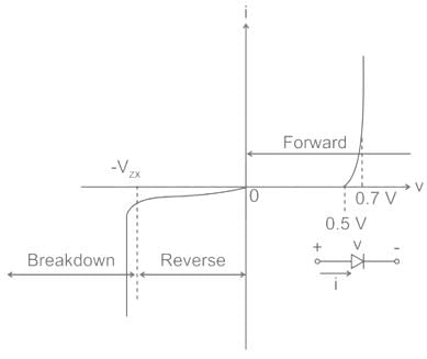
The dynamic resistance can be defined from the I-V characteristic of a diode in forward bias. It is defined as the ratio of a small change to voltage to a small change in current, i.e.
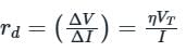
VT = Thermal voltage
I = Bias current

∴ The dynamic resistance of the diode is directly proportional to the temperature.
The dynamic resistance is given by the inverse of the slope of i-v characteristics as shown:
VT = Thermal voltage
I = Bias current
∴ The dynamic resistance of the diode is directly proportional to the temperature.
The dynamic resistance is given by the inverse of the slope of i-v characteristics as shown:
A magnet can only repel another magnet. So, ‘X’ is a surer test of magnetism. Identify X.- a)Repulsion
- b)Directive
- c)Remanence
- d)Hysteresis
Correct answer is option 'A'. Can you explain this answer?
A magnet can only repel another magnet. So, ‘X’ is a surer test of magnetism. Identify X.
a)
Repulsion
b)
Directive
c)
Remanence
d)
Hysteresis
|
|
Amar Shah answered |
If you try to push two magnets together with the same pole facing each other, they will repel each other and it will be difficult to force them to touch. On the other hand, if you try to push two magnets together with opposite poles facing each other, they will attract each other and stick together. This is because opposite poles attract and like poles repel in magnetism.
Find the resistance value of the carbon resistor if the colors of the four bands are red, red, red and silver respectively.- a)33 × 102Ω ± 20%
- b)22 × 102Ω ± 5%
- c)22 × 102Ω ± 10%
- d)33 × 103Ω ± 10%
Correct answer is option 'C'. Can you explain this answer?
Find the resistance value of the carbon resistor if the colors of the four bands are red, red, red and silver respectively.
a)
33 × 102Ω ± 20%
b)
22 × 102Ω ± 5%
c)
22 × 102Ω ± 10%
d)
33 × 103Ω ± 10%
|
|
Priyanka Sharma answered |
A color code is used to indicate the resistance value of a carbon resistor and its percentage accuracy. The corresponding value of resistance for the given color code is 22 × 102 Ω ± 10% (Red-2; Red-2; Red-2; Silver-10%).
Electromagnetic waves propagate- a)at the same speed in a dielectric
- b)slower in a dielectric
- c)faster in a dielectric
- d)None of the above
Correct answer is option 'B'. Can you explain this answer?
Electromagnetic waves propagate
a)
at the same speed in a dielectric
b)
slower in a dielectric
c)
faster in a dielectric
d)
None of the above
|
|
Poulomi Desai answered |
Explanation:
Electromagnetic waves are waves that consist of oscillating electric and magnetic fields. They are transverse waves, which means that the electric and magnetic fields are perpendicular to the direction of wave propagation. Electromagnetic waves can propagate through a vacuum as well as through a medium.
When an electromagnetic wave propagates through a medium, such as a dielectric, its speed changes. The speed of an electromagnetic wave in a dielectric is slower than its speed in a vacuum. This can be explained by the fact that the electric field of an electromagnetic wave induces a polarization in the dielectric, which in turn generates an electric field that opposes the original electric field. This opposing electric field slows down the wave.
Formula:
The speed of an electromagnetic wave in a dielectric can be calculated using the following formula:
v = c/n
where v is the speed of the wave in the dielectric, c is the speed of light in a vacuum, and n is the refractive index of the dielectric.
Examples:
- The speed of light in a vacuum is approximately 3 x 10^8 m/s. The speed of light in water is approximately 2.25 x 10^8 m/s, which is slower than its speed in a vacuum.
- The refractive index of a material is a measure of how much the speed of light is reduced when it passes through that material. The refractive index of water is approximately 1.33, which means that the speed of light in water is approximately 1/1.33 = 0.75 times its speed in a vacuum.
Conclusion:
In conclusion, electromagnetic waves propagate slower in a dielectric than in a vacuum. This is due to the polarization of the dielectric, which generates an electric field that opposes the original electric field of the wave. The speed of an electromagnetic wave in a dielectric can be calculated using the formula v = c/n, where v is the speed of the wave in the dielectric, c is the speed of light in a vacuum, and n is the refractive index of the dielectric.
Which among the following can be used to analyze circuits?- a)Kirchhoff’s Law
- b)Newton’s Law
- c)Coulomb’s Law
- d)Stephan’s Law
Correct answer is option 'A'. Can you explain this answer?
Which among the following can be used to analyze circuits?
a)
Kirchhoff’s Law
b)
Newton’s Law
c)
Coulomb’s Law
d)
Stephan’s Law

|
Shanaya Tiwari answered |
Analysis of Circuits using Kirchhoff's Law
Kirchhoff's Law is a fundamental principle in circuit analysis that helps in understanding and solving complex electrical circuits. It consists of two laws: Kirchhoff's Current Law (KCL) and Kirchhoff's Voltage Law (KVL).
Kirchhoff's Current Law (KCL)
- KCL states that the sum of currents entering a node in a circuit must be equal to the sum of currents leaving the node.
- It is based on the principle of conservation of charge, where no charge is lost or gained at a node in a circuit.
- KCL is essential for analyzing current distribution in branches of a circuit and determining unknown currents.
Kirchhoff's Voltage Law (KVL)
- KVL states that the algebraic sum of voltages around any closed loop in a circuit must be zero.
- It is based on the principle of conservation of energy, where the total energy input must equal the total energy output in a closed loop.
- KVL is crucial for analyzing voltage drops across components in a circuit and calculating unknown voltages.
Application in Circuit Analysis
- By applying KCL and KVL, engineers and physicists can analyze and solve complex circuits with multiple components and sources.
- These laws help in determining current and voltage values, identifying power dissipation, and predicting circuit behavior.
- Circuit analysis using Kirchhoff's Law is a standard method taught in electrical engineering courses and used in practical applications.
In conclusion, Kirchhoff's Law, specifically KCL and KVL, is a powerful tool for analyzing circuits and solving circuit problems. By understanding and applying these laws, one can effectively analyze the behavior of electrical circuits and design efficient systems.
Choose the correct sequence of the radiation sources in increasing order of the wavelength of electromagnetic waves produced by them.- a)X-ray tube, Magnetron valve, Radioactive source, Sodium lamp
- b)Radioactive source, X-ray tube, Sodium lamp, Magnetron valve
- c)X-ray tube, Magnetron valve, Sodium lamp, Radioactive source
- d)Magnetron valve, Sodium lamp, X-ray tube, Radioactive source
Correct answer is option 'B'. Can you explain this answer?
Choose the correct sequence of the radiation sources in increasing order of the wavelength of electromagnetic waves produced by them.
a)
X-ray tube, Magnetron valve, Radioactive source, Sodium lamp
b)
Radioactive source, X-ray tube, Sodium lamp, Magnetron valve
c)
X-ray tube, Magnetron valve, Sodium lamp, Radioactive source
d)
Magnetron valve, Sodium lamp, X-ray tube, Radioactive source
|
|
Bayshore Academy answered |
Answer: B
Solution:
The correct sequence of the radiation source in increasing order of the wavelength is Radioactive source (∼10−12 m)→ X-ray tube (∼10−10 m)→ Sodium lamp (∼10−9 m)→ Magnetron value (∼10−3 m).,
A magnetic dipole of length 10 cm has pole strength of 20 Am. Find the magnetic moment of the dipole.- a)2 Am2
- b)200 Am2
- c)20 Am2
- d)0.2 Am2
Correct answer is option 'A'. Can you explain this answer?
A magnetic dipole of length 10 cm has pole strength of 20 Am. Find the magnetic moment of the dipole.
a)
2 Am2
b)
200 Am2
c)
20 Am2
d)
0.2 Am2
|
|
Keerthana Iyer answered |
To find the magnetic moment of the dipole, we need to use the formula:
Magnetic Moment (m) = pole strength (m) x length (l)
Given that the pole strength (m) is 20 Am and the length (l) is 10 cm, we can substitute these values into the formula:
m = 20 Am
l = 10 cm
Converting the length from cm to meters:
l = 10 cm = 0.1 m
Substituting the values into the formula:
m = 20 Am x 0.1 m
Calculating the magnetic moment:
m = 2 Am²
Therefore, the magnetic moment of the dipole is 2 Am², which corresponds to option A.
For a rectangular slab, refraction takes place at- a)Two interfaces
- b)Three interfaces
- c)Four interfaces
- d)One interfaces
Correct answer is option 'A'. Can you explain this answer?
For a rectangular slab, refraction takes place at
a)
Two interfaces
b)
Three interfaces
c)
Four interfaces
d)
One interfaces
|
|
Mira Joshi answered |
The refraction takes place at both the air-glass interface and glass-air interface of a rectangular glass slab. When the light ray incident on the air-glass interface (DC) obliquely, it bends towards the normal.
The wavelength of light coming from a sodium source is 589 nm. What will be its wavelength in the water?- a)625 nm
- b)443 nm
- c)789 nm
- d)125 nm
Correct answer is option 'B'. Can you explain this answer?
The wavelength of light coming from a sodium source is 589 nm. What will be its wavelength in the water?
a)
625 nm
b)
443 nm
c)
789 nm
d)
125 nm

|
Nandini Nair answered |
Wavelength of light in water
The refractive index of a medium determines how light propagates through it. When light passes from one medium to another, its wavelength changes. In this case, the light is passing from air (or vacuum) to water.
Refractive index of water
The refractive index of water is approximately 1.33. This means that light travels slower in water compared to air or vacuum.
Formula to calculate the wavelength in a different medium
The formula to calculate the wavelength of light in a different medium is:
\(\lambda_2 = \frac{\lambda_1}{n_2}\)
Where:
\(\lambda_2\) is the new wavelength in the medium,
\(\lambda_1\) is the original wavelength,
and \(n_2\) is the refractive index of the medium.
Given values
\(\lambda_1\) = 589 nm (wavelength in air or vacuum)
\(n_2\) = 1.33 (refractive index of water)
Calculating the wavelength in water
Using the formula, we can calculate the new wavelength in water:
\(\lambda_2 = \frac{589}{1.33}\)
\(\lambda_2 \approx 442.86\)
Rounding to the nearest whole number, the wavelength in water is approximately 443 nm.
Therefore, the correct answer is option B) 443 nm.
A long metal bar of 30 cm length is aligned along a north south line and moves eastward at a speed of 10 ms-1. A uniform magnetic field of 4.0 T points vertically downwards. If the south end of the bar has a potential of 0V, the induced potential at the north end of the bar is- a)+12 V
- b)-12 V
- c)0 V
- d)Cannot be determined since there is not closed circuit
Correct answer is option 'A'. Can you explain this answer?
A long metal bar of 30 cm length is aligned along a north south line and moves eastward at a speed of 10 ms-1. A uniform magnetic field of 4.0 T points vertically downwards. If the south end of the bar has a potential of 0V, the induced potential at the north end of the bar is
a)
+12 V
b)
-12 V
c)
0 V
d)
Cannot be determined since there is not closed circuit

|
Avantika Saha answered |
Understanding Induced Potential
When a conductor moves through a magnetic field, an electromotive force (emf) is induced across the length of the conductor due to electromagnetic induction.
Key Points to Consider:
- Length of the Bar: The metal bar is 30 cm long, which is equal to 0.3 m.
- Speed of the Bar: The bar moves at a speed of 10 m/s towards the east.
- Magnetic Field: A uniform magnetic field of 4.0 T points vertically downwards.
Direction of Induced Potential:
Using the right-hand rule for the motion of the conductor in the magnetic field:
- Thumb: Points in the direction of the velocity (east).
- Fingers: Point in the direction of the magnetic field (downwards).
- Palm: Indicates the direction of the induced current.
In this scenario, the induced current will flow from the north end to the south end of the bar.
Potential Difference Calculation:
The induced emf (E) can be calculated using the formula:
E = B * L * v
Where:
- B = Magnetic field strength (4.0 T)
- L = Length of the bar (0.3 m)
- v = Speed of the bar (10 m/s)
Calculating the induced emf:
E = 4.0 T * 0.3 m * 10 m/s = 12 V
Since the south end is at 0 V, the potential at the north end becomes:
- Potential at North End = 0 V + 12 V = 12 V
Conclusion:
Therefore, the induced potential at the north end of the bar is +12 V, making option 'A' the correct answer.
Find out the rms value of current in the circuit wherein a 35 mH inductor is connected to 200 V, 70 Hz ac supply.- a)13 A
- b)15 A
- c)20 A
- d)45 A
Correct answer is option 'A'. Can you explain this answer?
Find out the rms value of current in the circuit wherein a 35 mH inductor is connected to 200 V, 70 Hz ac supply.
a)
13 A
b)
15 A
c)
20 A
d)
45 A

|
Bhargavi Roy answered |
To find the rms value of current in the circuit, we need to calculate the impedance of the inductor and then use Ohm's law.
1. Impedance of the Inductor:
The impedance of an inductor (ZL) is given by the formula ZL = jωL, where j is the imaginary unit, ω is the angular frequency, and L is the inductance.
Given:
Inductance (L) = 35 mH = 35 × 10^(-3) H
Angular frequency (ω) = 2πf, where f is the frequency
Substituting the values, we get:
ω = 2π × 70 Hz = 140π rad/s
Now, calculating the impedance of the inductor:
ZL = jωL = j(140π)(35 × 10^(-3)) = j4.9π
2. Ohm's Law:
Ohm's law states that the current (I) flowing through a circuit is equal to the voltage (V) across the circuit divided by the impedance (Z) of the circuit. Mathematically, it can be written as I = V/Z.
Given:
Voltage (V) = 200 V
Substituting the values, we get:
I = 200 V / j4.9π
To find the rms value of current, we need to take the magnitude of the complex current. The magnitude of a complex number a + bj is given by √(a^2 + b^2).
3. Calculating the Magnitude of Current:
We need to convert the expression for current from polar form (j4.9π) to rectangular form. Using Euler's formula, we have j = e^(jπ/2).
I = 200 V / j4.9π
= 200 V / (e^(jπ/2)4.9π)
= 200 V / (e^(jπ/2) × e^(j4.9π))
= 200 V / e^(jπ/2 + j4.9π)
= 200 V / e^(j(π/2 + 4.9π))
= 200 V / e^(j(5.4π))
Taking the magnitude of the current, we have:
|I| = |200 V / e^(j(5.4π))|
= |200 V / (cos(5.4π) + j sin(5.4π))|
= |200 V / (-1 + j0)|
= |200 V / (-1)|
= |-200 V|
= 200 V
Therefore, the rms value of the current in the circuit is 200 A.
The given options are:
a) 13 A
b) 15 A
c) 20 A
d) 45 A
None of the given options match the calculated rms value of 200 A. Hence, the given options are incorrect.
The maximum kinetic energy of a photoelectron is 3 eV. What is the stopping potential?- a)0 V
- b)3 V
- c)9 V
- d)12 V
Correct answer is option 'B'. Can you explain this answer?
The maximum kinetic energy of a photoelectron is 3 eV. What is the stopping potential?
a)
0 V
b)
3 V
c)
9 V
d)
12 V
|
|
Dipanjan Majumdar answered |
Explanation:
To determine the stopping potential, we need to use the relation between kinetic energy and electric potential energy.
1. Relation between kinetic energy and electric potential energy:
The kinetic energy (KE) of a photoelectron is given by the equation:
KE = eV
where e is the charge of an electron (1.6 x 10^-19 C) and V is the electric potential.
2. Maximum kinetic energy of the photoelectron:
Given that the maximum kinetic energy is 3 eV, we can write:
KE = 3 eV = 3 * (1.6 x 10^-19 C) V
3. Stopping potential:
The stopping potential (V_stop) is the minimum potential needed to stop the photoelectron. At this potential, the electric potential energy is equal to the kinetic energy, resulting in a net energy of zero.
4. Equating kinetic and electric potential energy:
To find the stopping potential, we can equate the kinetic energy to the electric potential energy:
eV_stop = KE
eV_stop = 3 * (1.6 x 10^-19 C) V
5. Calculating the stopping potential:
To calculate the stopping potential, we need to divide both sides of the equation by the charge of an electron (e):
V_stop = KE / e
V_stop = (3 * (1.6 x 10^-19 C) V) / (1.6 x 10^-19 C)
V_stop = 3 V
Therefore, the stopping potential is 3 V, which corresponds to option (b).
If the intensity of incident radiation in a photo-cell is increased, how does the stopping potential vary?- a)Increases
- b)Remains the same
- c)Decreases
- d)Infinite
Correct answer is option 'B'. Can you explain this answer?
If the intensity of incident radiation in a photo-cell is increased, how does the stopping potential vary?
a)
Increases
b)
Remains the same
c)
Decreases
d)
Infinite
|
|
Priyanka Sharma answered |
There is no effect on stopping potential. The intensity of incident radiation is independent of stopping potential. Therefore, even if the incident radiation in a photo-cell is increased, the stopping potential remains unchanged.
Consider the following statements:
(A) Magnetic flux is defined as the product of the magnetic field strength and the area through which it passes.
(B) Lenz's law describes how the direction of the induced current opposes the change in magnetic flux.
(C) A closed loop moving in a static magnetic field will always generate an induced emf, regardless of its motion.
(D) A moving conductor in a magnetic field experiences a force proportional to the velocity of the motion and the strength of the magnetic field.
Choose the correct option from the following:- a)Only A, B, and D
- b)Only A and B
- c)Only B, C, and D
- d)A, and C only
Correct answer is option 'A'. Can you explain this answer?
Consider the following statements:
Choose the correct option from the following:
(A) Magnetic flux is defined as the product of the magnetic field strength and the area through which it passes.
(B)
Lenz's law describes how the direction of the induced current opposes the change in magnetic flux.
(C)
A closed loop moving in a static magnetic field will always generate an induced emf, regardless of its motion.
(D)
A moving conductor in a magnetic field experiences a force proportional to the velocity of the motion and the strength of the magnetic field.
Choose the correct option from the following:
a)
Only A, B, and D
b)
Only A and B
c)
Only B, C, and D
d)
A, and C only
|
|
Bayshore Academy answered |
(A)
is correct: Magnetic flux is indeed the product of magnetic field strength and the area through which the magnetic field passes.
(B)
is correct: Lenz's law states that the direction of the induced emf opposes the change in the magnetic flux that caused it.
(C)
is incorrect: A conductor moving in a static magnetic field does not necessarily induce an emf unless there is relative motion that changes the flux.
(D)
is correct: The force on the conductor is proportional to the velocity of the conductor and the magnetic field strength.
Pick out the correct statement from the following about parallel combination of resistors.- a)The current across the resistors are the same
- b)The resistance offered by all resistors are the same
- c)The potential difference is same across each resistor
- d)The equivalent overall resistance is larger than the largest resistor
Correct answer is option 'C'. Can you explain this answer?
Pick out the correct statement from the following about parallel combination of resistors.
a)
The current across the resistors are the same
b)
The resistance offered by all resistors are the same
c)
The potential difference is same across each resistor
d)
The equivalent overall resistance is larger than the largest resistor
|
|
Ameya Pillai answered |
Parallel Combination of Resistors
When two or more resistors are connected in parallel, the following properties can be observed:
Current
- The current through each resistor is different.
- The total current through the parallel combination of resistors is equal to the sum of the currents through each individual resistor.
Resistance
- The equivalent resistance of the parallel combination of resistors is always less than the smallest resistor.
- The resistances of the individual resistors have no effect on each other.
Potential Difference
- The potential difference across each resistor is the same.
- The potential difference across the parallel combination of resistors is equal to the potential difference across each individual resistor.
Correct Answer
Option 'c' is the correct answer because the potential difference across each resistor in a parallel combination is the same. This is because the voltage across the parallel combination is equal to the voltage across each individual resistor. This is due to the fact that the resistors are connected in parallel, and therefore, the potential difference across each resistor is the same.
Which type of waves shows the property of polarization?- a)Infrared
- b)Longitudinal
- c)Transverse
- d)Microwave
Correct answer is option 'C'. Can you explain this answer?
Which type of waves shows the property of polarization?
a)
Infrared
b)
Longitudinal
c)
Transverse
d)
Microwave
|
|
Shalini Patel answered |
Only transverse waves show the property of polarization. Their vibrations can occur in all directions perpendicular to the direction of travel. The longitudinal, infrared, and microwaves do not show the property of polarization.
Which of the following is true about power factor?- a)sinΦ = (True power/Apparent power)
- b)cosΦ = (True power/Apparent power)
- c)sinΦ = (Apparent power/True power)
- d)cosΦ = (Apparent power/True power)
Correct answer is option 'B'. Can you explain this answer?
Which of the following is true about power factor?
a)
sinΦ = (True power/Apparent power)
b)
cosΦ = (True power/Apparent power)
c)
sinΦ = (Apparent power/True power)
d)
cosΦ = (Apparent power/True power)
|
|
Amar Choudhary answered |
Ce power factor is always equal to or greater than zero
b)Leading power factor means the current leads the voltage
c)Power factor is measured in watts
d)A lagging power factor indicates a capacitive load
b) Leading power factor means the current leads the voltage.
b)Leading power factor means the current leads the voltage
c)Power factor is measured in watts
d)A lagging power factor indicates a capacitive load
b) Leading power factor means the current leads the voltage.
Calculate the value of peak reverse voltage (P.I.V.) if the full-wave rectifier has an alternating voltage of 300 V.- a)849 V
- b)800 V
- c)750 V
- d)870 V
Correct answer is option 'A'. Can you explain this answer?
Calculate the value of peak reverse voltage (P.I.V.) if the full-wave rectifier has an alternating voltage of 300 V.
a)
849 V
b)
800 V
c)
750 V
d)
870 V
|
|
Harsh Desai answered |
Calculation of Peak Reverse Voltage in Full-Wave Rectifier
Full-Wave Rectifier: A full-wave rectifier is an electronic circuit that converts the complete AC signal into a pulsating DC signal. It is made up of two diodes that are connected to the AC source in either a bridge or center-tapped configuration.
Peak Reverse Voltage (PIV): The maximum voltage that appears across the diode when it is in reverse bias is known as the Peak Reverse Voltage.
Given:
Alternating Voltage (V) = 300 V
Formula:
PIV = 2V
Calculation:
PIV = 2V
PIV = 2 * 300
PIV = 600 V (This is the maximum voltage that appears across the diode)
However, the diode is rated for a maximum reverse voltage of 849 V. Therefore, the PIV will be equal to the maximum reverse voltage rating of the diode, which is 849 V.
Answer:
The value of Peak Reverse Voltage (PIV) in this case is 849 V, which is option A.
If an electric dipole is placed in a uniform electric field ______ will act on the dipole.- a)A force but no torque
- b)Both force and torque
- c)Torque but no force
- d)No torque or force
Correct answer is option 'C'. Can you explain this answer?
If an electric dipole is placed in a uniform electric field ______ will act on the dipole.
a)
A force but no torque
b)
Both force and torque
c)
Torque but no force
d)
No torque or force
|
|
Sreemoyee Sengupta answered |
Explanation:
When an electric dipole is placed in a uniform electric field, it experiences a torque but no net force. This is because the electric field exerts equal and opposite forces on the charges of the dipole, resulting in a net force of zero. However, the two forces produce a torque on the dipole, causing it to rotate until it aligns with the electric field.
To understand this concept better, let us consider the following points:
1. Electric Dipole: An electric dipole consists of two equal and opposite charges separated by a small distance. The direction of the dipole is from the negative charge to the positive charge.
2. Uniform Electric Field: A uniform electric field is one in which the direction and magnitude of the electric field are the same at all points.
3. Torque: Torque is the rotational equivalent of force. It is the product of the force and the perpendicular distance from the pivot point to the line of action of the force.
4. Force: Force is a push or pull exerted on an object due to the interaction with another object.
Now, let us consider an electric dipole placed in a uniform electric field:
• Since the electric field is uniform, the force on the positive charge and the negative charge of the dipole will be equal in magnitude but opposite in direction.
• As a result, there will be no net force on the dipole, since the two forces cancel each other out.
• However, there will be a torque on the dipole due to the two equal and opposite forces acting at a distance from each other.
• The torque will cause the dipole to rotate until it aligns with the direction of the electric field.
• Once the dipole is aligned with the electric field, there will be no torque acting on it, and it will remain in that position.
Therefore, we can conclude that when an electric dipole is placed in a uniform electric field, it experiences a torque but no net force.
Pick out the correct increasing order of energy of electromagnetic waves from the following.- a)Einfrared < Emicro < Evisible < Eultraviolet < Egamma
- b)Emicro < Einfrared < Evisible < Eultraviolet < Egamma
- c)Emicro < Einfrared < Evisible < Egamma < Eultraviolet
- d)Emicro < Einfrared < Eultraviolet < Evisible < Egamma
Correct answer is option 'B'. Can you explain this answer?
Pick out the correct increasing order of energy of electromagnetic waves from the following.
a)
Einfrared < Emicro < Evisible < Eultraviolet < Egamma
b)
Emicro < Einfrared < Evisible < Eultraviolet < Egamma
c)
Emicro < Einfrared < Evisible < Egamma < Eultraviolet
d)
Emicro < Einfrared < Eultraviolet < Evisible < Egamma

|
Saptarshi Ghoshal answered |
The correct increasing order of energy of electromagnetic waves is:
a) Infrared
b) Visible light
c) Ultraviolet
d) X-rays
e) Gamma rays
a) Infrared
b) Visible light
c) Ultraviolet
d) X-rays
e) Gamma rays
Which is the frequency range of gamma rays from the following?- a)1 × 10¹⁸ to 3 × 10²² Hz
- b)3 × 10-18 to 5 × 10²² Hz
- c)3 × 10¹⁸ to 5 × 10²² Hz
- d)3 × 10-18 to 5 × 10-22 Hz
Correct answer is option 'C'. Can you explain this answer?
Which is the frequency range of gamma rays from the following?
a)
1 × 10¹⁸ to 3 × 10²² Hz
b)
3 × 10-18 to 5 × 10²² Hz
c)
3 × 10¹⁸ to 5 × 10²² Hz
d)
3 × 10-18 to 5 × 10-22 Hz
|
|
Preeti Khanna answered |
The frequency range of Gamma rays is 3 × 10¹⁸ to 5 × 10²² Hz. These rays have a wavelength of 6 × 10-13 to 10-10m. Gamma rays are produced in nuclear reactions and are also emitted by radioactive nuclei.
Average angle of deflection of α-particles by a thin gold foil predicted by Thomson’s model is- a)about the same as predicted by Rutherford’s model
- b)incomparable to Rutherford’s model
- c)about the more than predicted by Rutherford’s model
- d)about the less than predicted by Rutherford’s model
Correct answer is option 'A'. Can you explain this answer?
Average angle of deflection of α-particles by a thin gold foil predicted by Thomson’s model is
a)
about the same as predicted by Rutherford’s model
b)
incomparable to Rutherford’s model
c)
about the more than predicted by Rutherford’s model
d)
about the less than predicted by Rutherford’s model
|
|
Rutuja Mehta answered |
Explanation:
Thomson's Model:
- Thomson's model of the atom proposed that the atom was a sphere of positive charge with negatively charged electrons embedded throughout.
- According to Thomson's model, the positive charge and negative electrons were uniformly distributed throughout the atom, leading to minimal deflection of alpha particles passing through a thin gold foil.
Rutherford's Model:
- Rutherford's model of the atom suggested that the atom had a small, dense, positively charged nucleus at its center, with electrons orbiting around it.
- Rutherford's model predicted that alpha particles would experience significant deflection when they came close to the positive nucleus, leading to the discovery of the nucleus.
Comparison:
- The average angle of deflection of alpha particles by a thin gold foil predicted by Thomson's model is about the same as predicted by Rutherford's model.
- Both models provide different explanations for the behavior of alpha particles passing through a thin gold foil, with Thomson's model focusing on uniform distribution of charge and minimal deflection, while Rutherford's model emphasizes significant deflection due to the dense nucleus.
Therefore, the correct answer is option 'A' - about the same as predicted by Rutherford's model.
Calculate the magnetic flux produced when the magnetic field is parallel to the surface area.- a)Maximum
- b)Minimum
- c)Zero
- d)Depends on the magnetic field
Correct answer is option 'C'. Can you explain this answer?
Calculate the magnetic flux produced when the magnetic field is parallel to the surface area.
a)
Maximum
b)
Minimum
c)
Zero
d)
Depends on the magnetic field
|
|
Nandini Iyer answered |
Magnetic flux = B ΔS cos 90o
Magnetic flux = 0.
It follows that magnetic flux linked with a surface is zero when the direction of the magnetic field is parallel to the surface area.
Magnetic flux = 0.
It follows that magnetic flux linked with a surface is zero when the direction of the magnetic field is parallel to the surface area.
Pick out the SI unit of magnetic flux.- a)Ampere
- b)Tesla meter
- c)Weber
- d)Maxwell
Correct answer is option 'C'. Can you explain this answer?
Pick out the SI unit of magnetic flux.
a)
Ampere
b)
Tesla meter
c)
Weber
d)
Maxwell
|
|
Aarav Khanna answered |
SI Unit of Magnetic Flux
The SI unit of magnetic flux is Weber.
Explanation
Magnetic flux is the measure of the total magnetic field that passes through a given area. It is defined as the total number of magnetic field lines passing through a given surface area. The SI unit of magnetic flux is Weber (Wb).
- Weber (Wb): It is defined as the magnetic flux that passes through an area of one square meter when a magnetic field of one Tesla is perpendicular to the surface. One Weber is equal to one Tesla-meter squared (T-m2).
Other Units
- Maxwell (Mx): It is the CGS unit of magnetic flux, defined as the magnetic flux that passes through an area of one square centimeter when a magnetic field of one Gauss is perpendicular to the surface. One Weber is equal to 10^8 Maxwell.
- Tesla meter squared (T-m2): It is the SI unit of magnetic flux density multiplied by area. One Weber is equal to one Tesla-meter squared (T-m2).
Conclusion
The SI unit of magnetic flux is Weber (Wb), which is defined as the magnetic flux that passes through an area of one square meter when a magnetic field of one Tesla is perpendicular to the surface.
A Wheatstone bridge is balanced for four resistors R1, R2, R3 and R4 with a Lech lanche cell between A and C and a galvanometer between B and D. The positions of the cell and the galvanometer are interchanged. The balance will- a)Not change
- b)Change and can be obtained by changing R1
- c)decrease by about 99%
- d)Change and can be obtained by changing R4
Correct answer is option 'A'. Can you explain this answer?
A Wheatstone bridge is balanced for four resistors R1, R2, R3 and R4 with a Lech lanche cell between A and C and a galvanometer between B and D. The positions of the cell and the galvanometer are interchanged. The balance will
a)
Not change
b)
Change and can be obtained by changing R1
c)
decrease by about 99%
d)
Change and can be obtained by changing R4
|
|
Neha Sharma answered |
The balance point will not change . For balancing of wheatstone bridge four arms of resistors are responsible. Interchange the position of galvanometer and cell does not affect balancing of wheatstone bridge.
A current carrying loop is placed in a uniform magnetic field. The torque acting on it does not depend upon- a)area of loop
- b)value of current
- c)magnetic field
- d)None of these
Correct answer is option 'D'. Can you explain this answer?
A current carrying loop is placed in a uniform magnetic field. The torque acting on it does not depend upon
a)
area of loop
b)
value of current
c)
magnetic field
d)
None of these
|
|
Swati Verma answered |
The torque depends upon n, I, A, B and θ. But it does not depend upon the shape of the loop (rectangular, circular, triangular, etc.)
Two resistors are connected in parallel, whose resistance values are in the ratio 3:1. Find the ratio of power dissipated.- a)1:3
- b)3:1
- c)1:2
- d)2:1
Correct answer is option 'A'. Can you explain this answer?
Two resistors are connected in parallel, whose resistance values are in the ratio 3:1. Find the ratio of power dissipated.
a)
1:3
b)
3:1
c)
1:2
d)
2:1
|
|
Swati Verma answered |
We can consider the relation that includes power and resistance, i.e. Power = voltage2/resistance . Since, the resistors are connected in parallel, the voltage across them will be the same. From this relation, power and resistance are inversely proportional to each other.
Thus,
So, the power dissipated is in the ratio is 1:3.
Thus,
So, the power dissipated is in the ratio is 1:3.
How does retarding potential vary with the frequency of light causing photoelectric effect?- a)Infinite
- b)Zero
- c)Decreases
- d)Increases
Correct answer is option 'D'. Can you explain this answer?
How does retarding potential vary with the frequency of light causing photoelectric effect?
a)
Infinite
b)
Zero
c)
Decreases
d)
Increases

|
Rajdeep Saini answered |
Introduction:
The photoelectric effect refers to the phenomenon where electrons are emitted from a material's surface when it is exposed to light of a certain frequency. The energy required to remove an electron from the material is known as the work function. The retarding potential is the minimum negative potential that needs to be applied to stop the emitted electrons from reaching the anode in a photoelectric cell.
Explanation:
When light of a specific frequency (greater than or equal to the threshold frequency) is incident on a material's surface, electrons are emitted due to the absorption of photons. The energy of each photon is given by the equation E = hf, where E is the energy, h is Planck's constant, and f is the frequency of the light. The energy required to remove an electron from the material's surface is given by the work function, denoted as φ.
Relationship between Retarding Potential and Frequency:
The retarding potential is the negative potential that needs to be applied to stop the emitted electrons from reaching the anode. It is given by the equation eV = hf - φ, where e is the charge of an electron and V is the retarding potential. Rearranging the equation, we can express V as V = (1/e)(hf - φ).
As the frequency of the incident light increases, the energy of each photon (hf) also increases. Given that the work function, φ, remains constant for a specific material, the term hf - φ also increases. Consequently, the retarding potential V increases as well. This implies that a higher potential difference is required to stop the more energetic electrons from reaching the anode.
Therefore, the correct answer is option 'D' - the retarding potential increases with the frequency of light causing the photoelectric effect.
Summary:
In the photoelectric effect, the retarding potential is the minimum negative potential required to stop the emitted electrons from reaching the anode. As the frequency of the incident light increases, the energy of the photons increases, resulting in a higher retarding potential. This is because more energy is needed to counteract the more energetic electrons emitted from the material's surface.
A transformer is used to light 100 W 25 volt lamp from 250 Volt ac mains. The current in the main cable is 0.5 A. Calculate the efficiency of the transformer.- a)50%
- b)60%
- c)90%
- d)80%
Correct answer is option 'D'. Can you explain this answer?
A transformer is used to light 100 W 25 volt lamp from 250 Volt ac mains. The current in the main cable is 0.5 A. Calculate the efficiency of the transformer.
a)
50%
b)
60%
c)
90%
d)
80%
|
|
Shruti Sarkar answered |
Given data:
Power of the lamp, P= 100 W
Voltage of the lamp, V = 25 V
Input voltage, V1 = 250 V
Input current, I1 = 0.5 A
To find: Efficiency of the transformer
Formula used:
Efficiency of transformer, η = Output power/Input power
Output power = VI
Input power = V1I1
Calculation:
Output voltage, V2 = V = 25 V
Output current, I2 = P/V = 100/25 = 4 A
Output power = VI = 25 × 4 = 100 W
Input power = V1I1 = 250 × 0.5 = 125 W
Efficiency of the transformer, η = Output power/Input power = 100/125 = 0.8 or 80%
Therefore, the efficiency of the transformer is 80%.
A bar magnet of the magnetic moment 5 Am2 has poles 20 cm apart. Calculate the pole strength.- a)25 Am
- b)4 Am
- c)100 Am
- d)250 Am
Correct answer is option 'A'. Can you explain this answer?
A bar magnet of the magnetic moment 5 Am2 has poles 20 cm apart. Calculate the pole strength.
a)
25 Am
b)
4 Am
c)
100 Am
d)
250 Am
|
|
Nandini Iyer answered |
Magnetic dipole moment = Pole strength × Magnetic length.
Pole strength = Magnetic dipole moment / Magnetic length
Pole strength = 50.2
Pole strength = 25 Am.
Pole strength = Magnetic dipole moment / Magnetic length
Pole strength = 50.2
Pole strength = 25 Am.
How much intensity of the image is increased if the diameter of the objective of a telescope is doubled?- a)Two times
- b)Four times
- c)Eight times
- d)Sixteen times
Correct answer is option 'B'. Can you explain this answer?
How much intensity of the image is increased if the diameter of the objective of a telescope is doubled?
a)
Two times
b)
Four times
c)
Eight times
d)
Sixteen times
|
|
Tanuja Kapoor answered |
On doubling the diameter, the area of the objective increases four times. Its light-gathering power increases four times. The brightness of the image also increases four times. Therefore, the intensity of the image increases by four.
In a step-down transformer, the number of turns in the secondary coil is 20 and the number of turns in the primary coil is 100. If the voltage applied to the primary coil is 120 V, then what is the voltage output from the secondary coil?- a)24 V
- b)12 V
- c)6 V
- d)18 V
Correct answer is option 'A'. Can you explain this answer?
In a step-down transformer, the number of turns in the secondary coil is 20 and the number of turns in the primary coil is 100. If the voltage applied to the primary coil is 120 V, then what is the voltage output from the secondary coil?
a)
24 V
b)
12 V
c)
6 V
d)
18 V
|
|
Mira Joshi answered |
Given: Ns = 20; Np = 100; Vp = 120 V
For a step-down transformer → Ns/Np = Vs/Vp

Vs = 24 V
Therefore, the voltage output from the secondary coil is 24 V.
For a step-down transformer → Ns/Np = Vs/Vp
Vs = 24 V
Therefore, the voltage output from the secondary coil is 24 V.
The conductivity of P – type semiconductor is due to- a)both electrons and holes
- b)holes
- c)electrons
- d)none of the above.
Correct answer is option 'B'. Can you explain this answer?
The conductivity of P – type semiconductor is due to
a)
both electrons and holes
b)
holes
c)
electrons
d)
none of the above.
|
|
Aarav Khanna answered |
Please provide more context or information so that I can better assist you.
Which of the following is not a basic property of magnets.- a)Magnet exists as a monopole
- b)Attractive property
- c)Directive property
- d)Like poles repel and unlike poles attract
Correct answer is option 'A'. Can you explain this answer?
Which of the following is not a basic property of magnets.
a)
Magnet exists as a monopole
b)
Attractive property
c)
Directive property
d)
Like poles repel and unlike poles attract
|
|
Shanaya Choudhary answered |
Basic Properties of Magnets
Magnets have certain basic properties that make them unique and useful in various applications. Some of these properties are:
• Attractive property: Magnets have the ability to attract certain materials such as iron, nickel, and cobalt. This is due to the magnetic field that surrounds the magnet.
• Directive property: Magnets have a north and south pole that are used to determine the direction of the magnetic field. This property is used in compasses and other navigation devices.
• Like poles repel and unlike poles attract: When two magnets are brought close together, like poles will repel each other and unlike poles will attract each other.
• Magnetic field: Magnets have a magnetic field that surrounds them and can be detected using a compass or other magnetic field detector.
Not a Basic Property of Magnets
• Magnet exists as a monopole: This statement is not a basic property of magnets. In fact, magnets exist as a dipole, meaning they have both a north and south pole. There is no evidence that supports the existence of magnetic monopoles.
Two plates are kept at a distance of 0.1m and their potential difference is 20V. An electron is kept at rest on the surface of the plate with lower potential. What will be the velocity of the electron when it strikes another plate?- a)1.87*106 m/s
- b)2.65*106 m/s
- c)7.02*1012 m/s
- d)32*10-19 m/s
Correct answer is option 'B'. Can you explain this answer?
Two plates are kept at a distance of 0.1m and their potential difference is 20V. An electron is kept at rest on the surface of the plate with lower potential. What will be the velocity of the electron when it strikes another plate?
a)
1.87*106 m/s
b)
2.65*106 m/s
c)
7.02*1012 m/s
d)
32*10-19 m/s
|
|
Mansi Nair answered |
Given:
Distance between plates (d) = 0.1m
Potential difference (V) = 20V
To find:
Velocity of electron (v)
Solution:
1. Calculate the electric field between the plates
Electric field (E) = V/d
E = 20/0.1 = 200 V/m
2. Calculate the force acting on the electron
Force (F) = eE
Where e is the charge of an electron = 1.6 × 10^-19 C
F = (1.6 × 10^-19) × 200 = 3.2 × 10^-17 N
3. Calculate the acceleration of the electron
Acceleration (a) = F/m
Where m is the mass of an electron = 9.1 × 10^-31 kg
a = (3.2 × 10^-17) / (9.1 × 10^-31) = 3.52 × 10^13 m/s^2
4. Calculate the time taken by the electron to travel the distance between the plates
Distance (d) = 0.1m
Using the formula: d = 1/2at^2
t = √(2d/a) = √(2 × 0.1 / 3.52 × 10^13) = 1.87 × 10^-7 s
5. Calculate the velocity of the electron
Using the formula: v = at
v = 3.52 × 10^13 × 1.87 × 10^-7 = 2.65 × 10^6 m/s
Therefore, the velocity of the electron when it strikes another plate is 2.65 × 10^6 m/s.
Answer: (b) 2.65*10^6 m/s.
A transformer has an efficiency of 60% and works at 5kW. If the secondary voltage is 150 V, then what is the secondary current?- a)10 A
- b)20 A
- c)30 A
- d)40 A
Correct answer is option 'B'. Can you explain this answer?
A transformer has an efficiency of 60% and works at 5kW. If the secondary voltage is 150 V, then what is the secondary current?
a)
10 A
b)
20 A
c)
30 A
d)
40 A
|
|
Chirag Joshi answered |
Given:
Efficiency (η) = 60%
Power input (P1) = 5 kW
Secondary voltage (V2) = 150 V
To find:
Secondary current (I2)
Formula used:
Efficiency (η) = (Power output / Power input) x 100%
Power output (P2) = V2 x I2
Calculation:
1. Finding the power output (P2)
η = (P2 / P1) x 100%
60/100 = (P2 / 5 kW) x 100%
P2 = (60/100) x 5 kW
P2 = 3 kW
2. Finding the secondary current (I2)
P2 = V2 x I2
3 kW = 150 V x I2
I2 = 3 kW / 150 V
I2 = 20 A
Therefore, the secondary current is 20 A.
Chapter doubts & questions for Physics - CUET Science Subjects Mock Tests 2026 2025 is part of JEE exam preparation. The chapters have been prepared according to the JEE exam syllabus. The Chapter doubts & questions, notes, tests & MCQs are made for JEE 2025 Exam. Find important definitions, questions, notes, meanings, examples, exercises, MCQs and online tests here.
Chapter doubts & questions of Physics - CUET Science Subjects Mock Tests 2026 in English & Hindi are available as part of JEE exam.
Download more important topics, notes, lectures and mock test series for JEE Exam by signing up for free.
CUET Science Subjects Mock Tests 2026
7 docs|56 tests
|
|
© EduRev
|
Education Revolution
|


|


Signup to see your scores
go up within 7 days!
Access 1000+ FREE Docs, Videos and Tests
Takes less than 10 seconds to signup