


All Exams >
Mechanical Engineering >
Design of Machine Elements >
All Questions
All questions of Threaded Joints & Power Screws for Mechanical Engineering Exam
Which of the following requires more space for the rotation of spanner?- a)Square Head
- b)Hexagonal Head
- c)Both require equal space of rotation
- d)Cannot be stated
Correct answer is option 'A'. Can you explain this answer?
Which of the following requires more space for the rotation of spanner?
a)
Square Head
b)
Hexagonal Head
c)
Both require equal space of rotation
d)
Cannot be stated

|
Sravya Tiwari answered |
Explanation: Angle of rotation for hexagonal head is one sixth of a revolution to enable the next pair of flats to be engaged while it is one fourth of a revolution in case of square head.

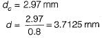
Two shafts are connected by means of a flange coupling to transmit torque of 25 N-m. The flanges of the coupling are fastened by four bolts of the same material at a radius of 30 mm. What is the size of bolts if the allowable shear stress for the botl material is 30 MPa?- a)M 4
- b)M 8
- c)M 12
- d)M 16
Correct answer is option 'A'. Can you explain this answer?
Two shafts are connected by means of a flange coupling to transmit torque of 25 N-m. The flanges of the coupling are fastened by four bolts of the same material at a radius of 30 mm. What is the size of bolts if the allowable shear stress for the botl material is 30 MPa?
a)
M 4
b)
M 8
c)
M 12
d)
M 16
|
|
Sai Reddy answered |
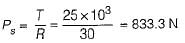
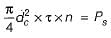
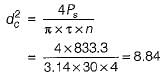
∴
If nominal diameter of screw thread=50mm and pitch=10mm then the mean diameter of the screw thread will be?- a)40mm
- b)45mm
- c)60mm
- d)55mm
Correct answer is option 'B'. Can you explain this answer?
If nominal diameter of screw thread=50mm and pitch=10mm then the mean diameter of the screw thread will be?
a)
40mm
b)
45mm
c)
60mm
d)
55mm
|
|
Saranya Saha answered |
Explanation: Diameter(mean)=Diameter(nominal) – 0.5P .
If a fastener is threaded into a tapped hole, then the fastener is likely to be called as- a)Screw
- b)Bolt
- c)Washer
- d)Screw or bolt
Correct answer is option 'A'. Can you explain this answer?
If a fastener is threaded into a tapped hole, then the fastener is likely to be called as
a)
Screw
b)
Bolt
c)
Washer
d)
Screw or bolt
|
|
Sarita Yadav answered |
Explanation: Bolt is threaded into a nut while screw is threaded into a tapped hole.

Trapezoidal threads screws have less load carrying capacity as compared to square thread screws.- a)True
- b)False
Correct answer is option 'B'. Can you explain this answer?
Trapezoidal threads screws have less load carrying capacity as compared to square thread screws.
a)
True
b)
False
|
|
Sandeep Sengupta answered |
Explanation: Square threads have less thickness at the core diameter and hence lower load carrying capacity.
For power transmission square threads- a)are least efficient
- b)are less rigid
- c)are expensive to manufacture
- d)wear out very fast
Correct answer is option 'C'. Can you explain this answer?
For power transmission square threads
a)
are least efficient
b)
are less rigid
c)
are expensive to manufacture
d)
wear out very fast
|
|
Dhruv Dasgupta answered |
Square thread:
1. Square threads are less efficient than trapezoidal thread.
2. Square threads are difficult to manufacture. They are usually turned on lathe with single point cutting tool.
3. The strength of a screw depends upon the thread thickness at the core diameter since square thread have less thickness at core than trapezoidal this reduces the load carrying capacity.
A machine vice whose length of the handle is 150mm and the coefficient of friction for thread and collar are 0.15 and 0.17 respectively has a force applied at handle of 125N. Also the outer and inner diameters of collar are 55mm and 45mm respectively. Find the collar torque in terms of clamping force W assuming uniform wear theory if nominal diameter=22mm and pitch=5mm.- a)4.5W
- b)5.4W
- c)4.25W
- d)3.37W
Correct answer is option 'C'. Can you explain this answer?
A machine vice whose length of the handle is 150mm and the coefficient of friction for thread and collar are 0.15 and 0.17 respectively has a force applied at handle of 125N. Also the outer and inner diameters of collar are 55mm and 45mm respectively. Find the collar torque in terms of clamping force W assuming uniform wear theory if nominal diameter=22mm and pitch=5mm.
a)
4.5W
b)
5.4W
c)
4.25W
d)
3.37W
|
|
Amrita Chauhan answered |
Explanation: M₂=0.17 x W x (55+45)/4 or M₂=4.25W N-mm.
If P is the pitch of a square thread, then the depth of thread d is given by- a)0.5 P
- b)P
- c)1.5 P
- d)2 P
Correct answer is option 'A'. Can you explain this answer?
If P is the pitch of a square thread, then the depth of thread d is given by
a)
0.5 P
b)
P
c)
1.5 P
d)
2 P
|
|
Atharva Majumdar answered |
The correct answer to the given question is option 'A', which states that the depth of thread (d) is equal to 0.5 times the pitch (P) of a square thread.
A square thread is a type of screw thread that has a square cross-section. It is commonly used in applications where a large amount of linear force is required, such as in vices, clamps, and jacks. The pitch of a square thread refers to the distance between adjacent threads, measured along the axis of the screw.
To understand why the depth of thread is half the pitch, let's break down the components of a square thread:
1. Pitch (P): The pitch is the distance between two adjacent threads. It is typically measured in millimeters or inches.
2. Depth of thread (d): The depth of thread is the distance from the crest (top) of the thread to the root (bottom) of the thread. It determines the engagement between the male and female threads.
Now, let's consider the geometry of a square thread:
- A square thread has equal height and width, resulting in a square-shaped cross-section.
- The depth of thread (d) is equal to the difference in height between the crest and root of the thread.
Based on the geometry of a square thread, we can deduce that the depth of thread is half the pitch:
- When a square thread is fully engaged, the crest of one thread is in contact with the root of the adjacent thread.
- This means that the depth of thread is equal to half the pitch, as the crest and root of adjacent threads align.
Therefore, the correct answer is option 'A', which states that the depth of thread (d) is equal to 0.5 times the pitch (P) of a square thread.
For bolts of uniform strength, the shank diameter is made equal to- a)major diameter of threads
- b)pitch diameter of threads
- c)minor diameter of threads
- d)nominal diameter of threads
Correct answer is option 'C'. Can you explain this answer?
For bolts of uniform strength, the shank diameter is made equal to
a)
major diameter of threads
b)
pitch diameter of threads
c)
minor diameter of threads
d)
nominal diameter of threads
|
|
Stuti Mishra answered |
Bolt of uniform strength are made by
1. Reducing the diameter of shank of bolt corresponding to that of minor diameter.
2. Making a hole and making the area of shank equal to root area.
1. Reducing the diameter of shank of bolt corresponding to that of minor diameter.
2. Making a hole and making the area of shank equal to root area.
Find the bending stress to which a screw of nominal diameter 22mm is subjected when the clamp exerts a force of 5kN acts on it. The screw is double threaded and pitch of screw is 5mm.Given: Coefficient of friction is 0.15.It is assumed operator exerts a force of 250N at the handle of length 275mm.- a)123.45N/mm²
- b)132.54N/mm²
- c)142.54N/mm²
- d)124.45N/mm²
Correct answer is option 'C'. Can you explain this answer?
Find the bending stress to which a screw of nominal diameter 22mm is subjected when the clamp exerts a force of 5kN acts on it. The screw is double threaded and pitch of screw is 5mm.Given: Coefficient of friction is 0.15.It is assumed operator exerts a force of 250N at the handle of length 275mm.
a)
123.45N/mm²
b)
132.54N/mm²
c)
142.54N/mm²
d)
124.45N/mm²
|
|
Kiran Basu answered |
Explanation: Bending stress=32M/πdᵌ where M=250 x 275N-mm,d=22-2 x 0.5 x 5mm.
Which of the following are true?- a)Cold working reduces toughness and ductility
- b)Cold worked components have poor resistance to shocks and vibrations
- c)Tooling for cold working is cheaper as compared to hot working
- d)All of the mentioned
Correct answer is option 'D'. Can you explain this answer?
Which of the following are true?
a)
Cold working reduces toughness and ductility
b)
Cold worked components have poor resistance to shocks and vibrations
c)
Tooling for cold working is cheaper as compared to hot working
d)
All of the mentioned
|
|
Anshul Basu answered |
Explanation: Properties of cold working.
A power screw is only used to convert rotary motion into linear motion and not for transmitting power.- a)True
- b)False
Correct answer is option 'B'. Can you explain this answer?
A power screw is only used to convert rotary motion into linear motion and not for transmitting power.
a)
True
b)
False
|
|
Soumya Basak answered |
Explanation: Power screw converts the motion from rotary to linear and is used for power transmission.
To ensure self-locking in a screw jack it is essential that helix angle is- a)larger than friction angle
- b)smaller than friction angle
- c)equal to friction angle
- d)such as to give maximum efficiency in lifting
Correct answer is option 'B'. Can you explain this answer?
To ensure self-locking in a screw jack it is essential that helix angle is
a)
larger than friction angle
b)
smaller than friction angle
c)
equal to friction angle
d)
such as to give maximum efficiency in lifting
|
|
Kalyan Chakraborty answered |
For.self locking
φ ≤ α (Friction angle > Helix angle)

(μ = tan φ)

φ ≤ α (Friction angle > Helix angle)
(μ = tan φ)
Clutch and coupling can be considered to be same.- a)True
- b)False
Correct answer is option 'B'. Can you explain this answer?
Clutch and coupling can be considered to be same.
a)
True
b)
False
|
|
Sankar Dasgupta answered |
Introduction:
Clutch and coupling are two mechanical devices used to connect or disconnect two rotating shafts. Although they serve similar purposes, they are not the same and have distinct characteristics and applications. This statement is false, and we will discuss the differences between clutch and coupling in detail.
Differences between Clutch and Coupling:
1. Function:
- Clutch: A clutch is used to engage or disengage power transmission between the engine and the transmission system in vehicles. It allows for smooth gear changes and control over the power flow.
- Coupling: A coupling is used to connect two shafts together to transmit torque and rotational motion without any slippage or power interruption.
2. Power Transmission:
- Clutch: Clutches are primarily designed for power transmission control, allowing the driver to engage or disengage the engine power from the transmission system.
- Coupling: Couplings are designed for efficient power transmission without any power interruption or slippage. They are used to transmit torque from one shaft to another.
3. Types:
- Clutch: Clutches are available in different types, such as friction clutches, hydraulic clutches, electromagnetic clutches, etc., depending on the application and requirements.
- Coupling: Couplings also come in various types, including rigid couplings, flexible couplings, fluid couplings, magnetic couplings, etc., to accommodate different shaft misalignments and vibration dampening needs.
4. Torque Limitation:
- Clutch: Clutches are designed to slip or disengage at higher torque values to protect the drivetrain components from damage due to excessive torque.
- Coupling: Couplings are designed to transmit torque efficiently without any slippage or disengagement. They can handle higher torque values compared to clutches.
5. Application:
- Clutch: Clutches are primarily used in vehicles, such as cars, motorcycles, trucks, etc., to control power transmission during gear changes.
- Coupling: Couplings are used in various applications, including industrial machinery, pumps, generators, conveyors, etc., where efficient power transmission and shaft alignment are required.
Conclusion:
In summary, clutch and coupling are two different mechanical devices with distinct functions, power transmission capabilities, torque limitations, and applications. While a clutch is primarily used for power transmission control in vehicles, a coupling is used to connect and transmit torque between two rotating shafts efficiently. Therefore, the statement that clutch and coupling can be considered the same is false.
Set screws are subjected to tensile forces only.- a)Yes
- b)No, they are subjected to compressive forces only
- c)Both compressive and tensile
- d)Can’t be determined
Correct answer is option 'B'. Can you explain this answer?
Set screws are subjected to tensile forces only.
a)
Yes
b)
No, they are subjected to compressive forces only
c)
Both compressive and tensile
d)
Can’t be determined
|
|
Bhargavi Chauhan answered |
Explanation: Set screws are subjected to compressive forces only.
What will be efficiency of the screw in case of raising the load when coefficient of friction is 0.1553 and tangent of helix angle is 0.0813?- a)34%
- b)45%
- c)54%
- d)43%
Correct answer is option 'A'. Can you explain this answer?
What will be efficiency of the screw in case of raising the load when coefficient of friction is 0.1553 and tangent of helix angle is 0.0813?
a)
34%
b)
45%
c)
54%
d)
43%
|
|
Athul Kumar answered |
Explanation: Efficiency= tanἀ(1-0.1553 x tan ἀ)/(0.1553+tanἀ).
What type of friction in cup design is recommended for the set screw?- a)Sliding
- b)Rolling
- c)Static
- d)None of the mentioned
Correct answer is option 'B'. Can you explain this answer?
What type of friction in cup design is recommended for the set screw?
a)
Sliding
b)
Rolling
c)
Static
d)
None of the mentioned
|
|
Jyoti Deshpande answered |
Friction in Cup Design for Set Screw
Introduction:
Friction plays a crucial role in the design of set screws used in various applications. The type of friction selected for the cup design determines the effectiveness of the set screw in holding objects together. Among the different types of friction, rolling friction is recommended for the set screw cup design.
Rolling Friction:
Rolling friction refers to the resistance encountered by a rolling object when it moves over a surface. It occurs when there is rolling contact between two surfaces, such as a wheel rolling on the ground. In the case of a set screw, the cup design involves a rolling motion when the screw is tightened or loosened.
Advantages of Rolling Friction:
1. Reduced Wear and Tear: Rolling friction offers lower wear and tear compared to other forms of friction like sliding friction. This is because rolling friction distributes the load over a larger contact area, reducing the pressure and minimizing surface damage.
2. Higher Efficiency: Rolling friction is more efficient than sliding friction as it requires less force to overcome. This results in smoother and easier tightening or loosening of the set screw.
3. Improved Grip: Rolling friction provides a better grip between the set screw and the surface it is being used on. This enhances the stability and prevents the screw from slipping or loosening unintentionally.
4. Reduced Jamming: Rolling friction reduces the likelihood of the set screw jamming or getting stuck in a particular position. This is particularly important in applications where the screw needs to be adjusted or removed frequently.
5. Enhanced Durability: The cup design with rolling friction helps to increase the overall durability and lifespan of the set screw. It minimizes the chances of damage or deformation to the screw threads, allowing for repeated use without compromising its performance.
Conclusion:
In conclusion, rolling friction is recommended for the cup design of set screws. It offers advantages such as reduced wear and tear, higher efficiency, improved grip, reduced jamming, and enhanced durability. These benefits make the set screw more reliable and efficient in various applications.
A machine vice whose length of the handle is 150mm and the coefficient of friction for thread and collar are 0.15 and 0.17 respectively has a force applied at handle of 125N. Also the outer and inner diameters of collar are 55mm and 45mm respectively. Find the screw torque in terms of clamping force W if nominal diameter=22mm and pitch=5mm.- a)3.567W N-mm
- b)2.286W N-mm
- c)3.564W N-mm
- d)None of the mentioned
Correct answer is option 'B'. Can you explain this answer?
A machine vice whose length of the handle is 150mm and the coefficient of friction for thread and collar are 0.15 and 0.17 respectively has a force applied at handle of 125N. Also the outer and inner diameters of collar are 55mm and 45mm respectively. Find the screw torque in terms of clamping force W if nominal diameter=22mm and pitch=5mm.
a)
3.567W N-mm
b)
2.286W N-mm
c)
3.564W N-mm
d)
None of the mentioned
|
|
Rishika Sen answered |
Screw torque can be calculated using the formula:
Torque = Force * Radius * Coefficient of friction
To calculate the radius (r), we need to find the mean diameter (d) of the collar, which can be calculated as:
Mean diameter (d) = (outer diameter + inner diameter) / 2
Given that the outer diameter (D) is 55mm and the inner diameter (d) is 45mm, we can substitute these values into the formula to find the mean diameter:
d = (55 + 45) / 2 = 50mm = 0.05m
The radius (r) is half the mean diameter, so:
r = d / 2 = 0.05 / 2 = 0.025m
Now we can calculate the screw torque:
Torque = Force * Radius * Coefficient of friction
Given that the force (F) is 125N and the coefficient of friction (μ) is 0.17, we can substitute these values into the formula:
Torque = 125 * 0.025 * 0.17
Simplifying the equation:
Torque = 2.125 N-m
Therefore, the screw torque in terms of the clamping force W is 2.125W N-m. However, none of the given options match this answer, so there may be an error in the options provided.
Torque = Force * Radius * Coefficient of friction
To calculate the radius (r), we need to find the mean diameter (d) of the collar, which can be calculated as:
Mean diameter (d) = (outer diameter + inner diameter) / 2
Given that the outer diameter (D) is 55mm and the inner diameter (d) is 45mm, we can substitute these values into the formula to find the mean diameter:
d = (55 + 45) / 2 = 50mm = 0.05m
The radius (r) is half the mean diameter, so:
r = d / 2 = 0.05 / 2 = 0.025m
Now we can calculate the screw torque:
Torque = Force * Radius * Coefficient of friction
Given that the force (F) is 125N and the coefficient of friction (μ) is 0.17, we can substitute these values into the formula:
Torque = 125 * 0.025 * 0.17
Simplifying the equation:
Torque = 2.125 N-m
Therefore, the screw torque in terms of the clamping force W is 2.125W N-m. However, none of the given options match this answer, so there may be an error in the options provided.
For overhauling condition- a)friction angle < helix angle
- b)friction angle > helix angle
- c)friction angle = helix angle
- d)none of these
Correct answer is option 'A'. Can you explain this answer?
For overhauling condition
a)
friction angle < helix angle
b)
friction angle > helix angle
c)
friction angle = helix angle
d)
none of these

|
Ashish Chakraborty answered |
The friction angle is a fundamental parameter used to describe the behavior of a material under shear stress. It represents the angle at which the material's internal resistance to shear stress is overcome and sliding occurs.
When considering the condition for overhauling, the friction angle becomes crucial in determining whether a material will experience sliding or not. In order for overhauling to occur, the shear stress acting on the material must exceed its internal resistance, as determined by the friction angle.
If the shear stress is greater than the product of the normal stress and the tangent of the friction angle, then overhauling will occur. Mathematically, this can be expressed as:
τ > σ * tan(φ)
where τ is the shear stress, σ is the normal stress, and φ is the friction angle.
To overhaul the condition, the friction angle can be increased by either changing the material or altering its properties. This can be achieved through various methods such as adding lubricants, changing the surface roughness, or modifying the material composition.
It is important to note that the friction angle is specific to each material and can vary depending on factors such as particle size, shape, and inter-particle forces. Therefore, a thorough understanding of the material's properties is essential when considering the condition for overhauling.
Maximum efficiency of a square threaded is given by- a)1-sinǾ/1+sinǾ
- b)1+sinǾ/1-sinǾ
- c)1-2sinǾ/1+2sinǾ
- d)1+2sinǾ/1-2sinǾ
Correct answer is option 'A'. Can you explain this answer?
Maximum efficiency of a square threaded is given by
a)
1-sinǾ/1+sinǾ
b)
1+sinǾ/1-sinǾ
c)
1-2sinǾ/1+2sinǾ
d)
1+2sinǾ/1-2sinǾ
|
|
Anjali Shah answered |
Explanation: Efficiency=Sin(2ἀ+Ǿ)-Sin Ǿ /Sin(2 ἀ+Ǿ+Sin Ǿ),For max efficiency, sin(2ἀ+ Ǿ)=1.
M 12 x 1.25 represents- a)fine pitch only
- b)coarse pitch only
- c)both fine and coarse pitch
- d)none of these
Correct answer is option 'A'. Can you explain this answer?
M 12 x 1.25 represents
a)
fine pitch only
b)
coarse pitch only
c)
both fine and coarse pitch
d)
none of these

|
Bhargavi Kulkarni answered |
The given representation M 12 x 1.25 is a standard notation used in mechanical engineering to describe the size and pitch of a threaded fastener. In this case, it specifically represents the characteristics of a metric thread.
This notation consists of several components, each providing specific information about the thread.
1. M: The letter "M" refers to the metric system. It indicates that the thread is measured in millimeters, which is the standard unit of measurement for metric threads.
2. 12: The number "12" represents the nominal diameter of the thread. In this case, it indicates that the thread has a diameter of 12 millimeters.
3. x: The letter "x" is used to separate the nominal diameter from the pitch value. It signifies that the following value refers to the pitch of the thread.
4. 1.25: The number "1.25" denotes the pitch of the thread. The pitch represents the distance between consecutive thread crests or valleys and is measured in millimeters. In this case, the pitch is 1.25 millimeters.
Now, let's understand why the correct answer is option A, which states that M 12 x 1.25 represents fine pitch only.
- Fine Pitch: In metric threads, fine pitch threads have a smaller pitch value compared to coarse pitch threads. They are commonly used in applications requiring higher precision, load-bearing capacity, or in situations where space is limited.
- Coarse Pitch: On the other hand, coarse pitch threads have a larger pitch value. They are typically used in applications that do not require high precision or load-bearing capacity but may require faster assembly or disassembly.
In the given notation, the pitch value mentioned is 1.25, which is relatively small. This indicates that the thread has a fine pitch. Therefore, the correct answer is option A, indicating that M 12 x 1.25 represents a fine pitch thread.
To summarize, the representation M 12 x 1.25 signifies a metric thread with a nominal diameter of 12 millimeters and a fine pitch of 1.25 millimeters.
Which type of joints is better when the product is subjected to large vibrations: welded or threaded?- a)Welded
- b)Threaded
- c)Both have same results
- d)Depends on the magnitude of the vibrational force
Correct answer is option 'A'. Can you explain this answer?
Which type of joints is better when the product is subjected to large vibrations: welded or threaded?
a)
Welded
b)
Threaded
c)
Both have same results
d)
Depends on the magnitude of the vibrational force

|
Abhishek Apoorv answered |
Explanation: Threaded joints loosen when subjected to vibration
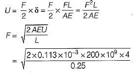
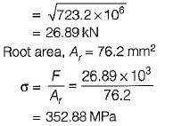
An M12 steel bolt, 250 mm long, is subjected to an impact load. The kinetic energy to be absorbed is 4 J. What is the stress in the shank of the bolt if there is no threaded portion between the nut and the bolt head? [Take root area = 76.2 mm2]- a)290 MPa
- b)300 MPa
- c)353 MPa
- d)373 MPa
Correct answer is option 'C'. Can you explain this answer?
An M12 steel bolt, 250 mm long, is subjected to an impact load. The kinetic energy to be absorbed is 4 J. What is the stress in the shank of the bolt if there is no threaded portion between the nut and the bolt head? [Take root area = 76.2 mm2]
a)
290 MPa
b)
300 MPa
c)
353 MPa
d)
373 MPa
|
|
Amrita Chauhan answered |
Stress area,
A = 0.785 x 122 x 10-6
= 0.113 x 10⁻³ m2
A = 0.785 x 122 x 10-6
= 0.113 x 10⁻³ m2
Screws used for power transmission should have- a)high efficiency
- b)low efficiency
- c)strong teeth
- d)all of the above
Correct answer is option 'A'. Can you explain this answer?
Screws used for power transmission should have
a)
high efficiency
b)
low efficiency
c)
strong teeth
d)
all of the above
|
|
Divyansh Goyal answered |
Screw used for power transmission should have
1. High efficiency
2. High strength
3. High load carrying capacity
4. Smooth and noise less
1. High efficiency
2. High strength
3. High load carrying capacity
4. Smooth and noise less
The resultant axial load on a bolt depends upon
1. external load applied
2. initial tension due to tightening of bolt
3. relative elastic yielding of the bolt and connected member
Which of the above statements are correct?- a)1 and 2
- b)1 and 3
- c)2 and 3
- d)1, 2 and 3
Correct answer is option 'D'. Can you explain this answer?
The resultant axial load on a bolt depends upon
1. external load applied
2. initial tension due to tightening of bolt
3. relative elastic yielding of the bolt and connected member
Which of the above statements are correct?
1. external load applied
2. initial tension due to tightening of bolt
3. relative elastic yielding of the bolt and connected member
Which of the above statements are correct?
a)
1 and 2
b)
1 and 3
c)
2 and 3
d)
1, 2 and 3
|
|
Niharika Iyer answered |
Axial Load on a Bolt
Axial load is the force that acts along the axis of a bolt. The axial load on a bolt is the result of the external load applied to the bolt and the initial tension due to tightening of the bolt. The relative elastic yielding of the bolt and connected member also affects the axial load on a bolt.
External Load Applied
The external load applied to a bolt can be in the form of tension, compression, or shear. The magnitude and direction of the external load determine the axial load on the bolt.
Initial Tension due to Tightening of Bolt
When a bolt is tightened, an initial tension is created in the bolt due to the elongation of the bolt. The initial tension in the bolt is proportional to the tightening torque applied to the bolt. The initial tension acts in the opposite direction of the external load and reduces the amount of external load that is transferred to the bolt.
Relative Elastic Yielding of the Bolt and Connected Member
The relative elastic yielding of the bolt and connected member also affects the axial load on a bolt. When external load is applied to a bolt, both the bolt and connected member deform elastically. If the bolt and connected member have different elastic properties, they will deform differently, resulting in a change in the axial load on the bolt.
Conclusion
The resultant axial load on a bolt depends upon the external load applied, initial tension due to tightening of bolt, and relative elastic yielding of the bolt and connected member. All three statements are correct, and therefore, the correct answer is option 'D'.
Multiple start threaded screws- a)increase the efficiency
- b)increase the capacity
- c)increase the mechanical advantage
- d)all of above
Correct answer is option 'A'. Can you explain this answer?
Multiple start threaded screws
a)
increase the efficiency
b)
increase the capacity
c)
increase the mechanical advantage
d)
all of above
|
|
Athul Kumar answered |
Advantages of multiple threaded screw.
1. It provides large axial motion per revolution of the screw, this increases the travelling speed of the sliding member.
2. The efficiency of multithreaded screw is more than single threaded screw due to increase in helix angle.
Note that the mechanical advantage obtained with multiple start threaded screw is lower than that of single threaded screw therefore the effort required to raise a particular load will be more in case of multiple start screw then single start.
Find the torque required to raise the load of 15kN and mean diameter of triple threaded screw being 46mm. Also given pitch=8mm and coefficient of friction is 0.15.- a)11831.06N-mm
- b)11813.06N-mm
- c)12811.06N-mm
- d)None of the listed
Correct answer is option 'A'. Can you explain this answer?
Find the torque required to raise the load of 15kN and mean diameter of triple threaded screw being 46mm. Also given pitch=8mm and coefficient of friction is 0.15.
a)
11831.06N-mm
b)
11813.06N-mm
c)
12811.06N-mm
d)
None of the listed

|
Bhaskar Joshi answered |
Torque Required to Raise the Load:
To calculate the torque required to raise the load, we need to consider the pitch of the screw, the coefficient of friction, and the load itself.
Given:
Load = 15 kN
Mean Diameter of Triple Threaded Screw (d) = 46 mm
Pitch (P) = 8 mm
Coefficient of Friction (µ) = 0.15
Calculating the Effective Diameter:
The effective diameter (de) of a triple-threaded screw can be calculated using the formula:
de = d - (2/3) * P
Substituting the given values:
de = 46 mm - (2/3) * 8 mm
de = 46 mm - 16/3 mm
de = 46 mm - 5.33 mm
de = 40.67 mm
Calculating the Lead Angle:
The lead angle (α) can be calculated using the formula:
tan α = P / (π * de)
Substituting the given values:
tan α = 8 mm / (π * 40.67 mm)
tan α = 8 mm / 128.04 mm
tan α = 0.0625
Using inverse tangent (tan^-1) function, we can find the value of α:
α = tan^-1(0.0625)
α ≈ 3.57 degrees
Calculating the Coefficient of Friction:
The coefficient of friction (µ) can be used to calculate the frictional force (Ff) acting on the screw. The formula for frictional force is:
Ff = µ * Load
Substituting the given values:
Ff = 0.15 * 15 kN
Ff = 2.25 kN
Calculating the Torque:
The torque (T) required to raise the load can be calculated using the formula:
T = (Ff * de) / 2
Substituting the values calculated above:
T = (2.25 kN * 40.67 mm) / 2
T = 91.66 kN-mm
T ≈ 11831.06 N-mm
Therefore, the torque required to raise the load of 15 kN with a mean diameter of 46 mm in a triple-threaded screw with a pitch of 8 mm and a coefficient of friction of 0.15 is approximately 11831.06 N-mm.
For a double threaded screw, what will be the tangent of helix angle if nominal diameter and pitch are 100mm and 12mm respectively?- a)0.045
- b)0.081
- c)0.094
- d)0.023
Correct answer is option 'B'. Can you explain this answer?
For a double threaded screw, what will be the tangent of helix angle if nominal diameter and pitch are 100mm and 12mm respectively?
a)
0.045
b)
0.081
c)
0.094
d)
0.023
|
|
Kiran Basu answered |
Explanation: tan ἀ= l/πd where l=2p, d=D-0.5p.
Which of the following is a wrong statement?- a)Pitch of a screw thread represents the distance from a point on one thread to the corresponding point on the adjacent thread.
- b)The distance which a screw thread advances axially in one rotation of the nut is called lead.
- c)A double start screws has two threads at some phase angle.
- d)Multiple threaded screws increase the load lifting capacity.
Correct answer is option 'D'. Can you explain this answer?
Which of the following is a wrong statement?
a)
Pitch of a screw thread represents the distance from a point on one thread to the corresponding point on the adjacent thread.
b)
The distance which a screw thread advances axially in one rotation of the nut is called lead.
c)
A double start screws has two threads at some phase angle.
d)
Multiple threaded screws increase the load lifting capacity.
|
|
Akshat Datta answered |
Multi-start threads are used where
(i) large load is required without reducing the cross-section of nut.
(ii) easy screwing is desired as in fountain pens and tooth paste caps. It is used where the use is to impart quick motion in opening and closing without exerting much force.
(i) large load is required without reducing the cross-section of nut.
(ii) easy screwing is desired as in fountain pens and tooth paste caps. It is used where the use is to impart quick motion in opening and closing without exerting much force.
What is the collar friction torque if outer and inner diameters are 100mm and 65mm respectively. Coefficient of friction is 0.15 and the load acting is of 15kN. Consider uniform wear theory.- a)89886.6N-mm
- b)38796.5N-mm
- c)92812.5N-mm
- d)87645.5N-mm
Correct answer is option 'C'. Can you explain this answer?
What is the collar friction torque if outer and inner diameters are 100mm and 65mm respectively. Coefficient of friction is 0.15 and the load acting is of 15kN. Consider uniform wear theory.
a)
89886.6N-mm
b)
38796.5N-mm
c)
92812.5N-mm
d)
87645.5N-mm
|
|
Hrishikesh Chakraborty answered |
Explanation: M=0.15 x W(D+d)/4.
A machine vice whose length of the handle is 150mm and the coefficient of friction for thread and collar are 0.15 and 0.17 respectively has a force applied at handle of 125N. Also the outer and inner diameters of collar are 55mm and 45mm respectively. Find the overall efficiency if nominal diameter=22mm and pitch=5mm.- a)18.12%
- b)12.18%
- c)21.23%
- d)23.21%
Correct answer is option 'B'. Can you explain this answer?
A machine vice whose length of the handle is 150mm and the coefficient of friction for thread and collar are 0.15 and 0.17 respectively has a force applied at handle of 125N. Also the outer and inner diameters of collar are 55mm and 45mm respectively. Find the overall efficiency if nominal diameter=22mm and pitch=5mm.
a)
18.12%
b)
12.18%
c)
21.23%
d)
23.21%
|
|
Keerthana Joshi answered |
Explanation: Efficiency= W l/2π(M₁+M₂) where
M₁=2.286W [M₁=Wd x tan (Ǿ+ἀ)/2 or M₁=W x (22-0.5×2.5) x tan (4.66’+8.531’)/2 as tan(ἀ)=l/πd and tan Ǿ=0.15].
M₂=4.25W [M₂=0.17 x W x (55+45)/4 or M₂=4.25W N-mm],
l=5mm,
W=2868.73N [Net torque=M₁+M₂ or 125 x 150=2.286W + 4.25W or W=2868.73N].
M₁=2.286W [M₁=Wd x tan (Ǿ+ἀ)/2 or M₁=W x (22-0.5×2.5) x tan (4.66’+8.531’)/2 as tan(ἀ)=l/πd and tan Ǿ=0.15].
M₂=4.25W [M₂=0.17 x W x (55+45)/4 or M₂=4.25W N-mm],
l=5mm,
W=2868.73N [Net torque=M₁+M₂ or 125 x 150=2.286W + 4.25W or W=2868.73N].
Identify the wrong statement:- a)the screw and nut put together comprise a screw pair
- b)when considering the length of bolt, the thickness of head is not taken into consideration
- c)turnbuckie is used where slight angular displacement is required
- d)if the nut is made of a weaker material than the bolt, then the height of nut should be more than the nominal diameter of bolt
Correct answer is option 'C'. Can you explain this answer?
Identify the wrong statement:
a)
the screw and nut put together comprise a screw pair
b)
when considering the length of bolt, the thickness of head is not taken into consideration
c)
turnbuckie is used where slight angular displacement is required
d)
if the nut is made of a weaker material than the bolt, then the height of nut should be more than the nominal diameter of bolt
|
|
Bhargavi Kulkarni answered |
Explanation:
The wrong statement is option C: turnbuckle is used where slight angular displacement is required.
What is a turnbuckle?
A turnbuckle is a device used to adjust the tension or length of ropes, cables, and other tensioning systems. It consists of two threaded eye bolts, one screwed into each end of a small metal frame, with a central body in between. The central body can be rotated to adjust the tension of the system.
Why is the statement wrong?
The statement is incorrect because turnbuckles are used to provide linear adjustment, not angular displacement. They are primarily used in tensioning systems where precise adjustment of tension is required, such as in scaffolding, fence installation, or guy wire systems.
Examples of turnbuckle usage:
- In scaffolding: Turnbuckles are used to adjust the tension in the scaffolding system to ensure stability and safety.
- In fence installation: Turnbuckles are used to tighten the tension wire in chain-link fences, preventing sagging.
- In guy wire systems: Turnbuckles are used to adjust the tension in guy wires, which are used to stabilize structures like radio towers or utility poles.
Conclusion:
The incorrect statement is option C because turnbuckles are not used for slight angular displacement, but rather for linear adjustment of tension in various applications.
A differential screw is defined as a mechanical device consisting of two screws connected in parallel.- a)True
- b)False
Correct answer is option 'B'. Can you explain this answer?
A differential screw is defined as a mechanical device consisting of two screws connected in parallel.
a)
True
b)
False
|
|
Mehul Yadav answered |
Explanation: The two screws are connected in series.
A power screw has no problem of wear as there is very less amount of friction associated.- a)True
- b)False
Correct answer is option 'B'. Can you explain this answer?
A power screw has no problem of wear as there is very less amount of friction associated.
a)
True
b)
False

|
Sagarika Patel answered |
(B) IS CORRECT ANSWER
Wear is a serious problem in power screws as there is high friction in threads.
Wear is a serious problem in power screws as there is high friction in threads.
The most important dimension in the design of nut is its- a)height
- b)size across flats
- c)size across corner
- d)inside diameter and thread size
Correct answer is option 'A'. Can you explain this answer?
The most important dimension in the design of nut is its
a)
height
b)
size across flats
c)
size across corner
d)
inside diameter and thread size
|
|
Aniket Saini answered |
The most important dimension in the design of a nut is its height. The height of a nut refers to the distance from the base of the nut to the top of the nut. This dimension plays a crucial role in determining the functionality and compatibility of the nut with other components in a mechanical system.
Here are the reasons why height is the most important dimension in the design of a nut:
1. Assembly and Disassembly: The height of the nut determines the amount of thread engagement between the nut and the bolt or stud. Sufficient thread engagement is essential for proper assembly and disassembly of the nut. If the height of the nut is too short, it may not provide enough thread engagement, leading to weak connections and the potential for loosening or failure. On the other hand, if the height is too tall, it may result in excessive thread engagement, making it difficult to assemble or disassemble the nut.
2. Clearance: The height of the nut also affects the clearance between the nut and the surrounding components. In many applications, there are space constraints, and it is important to ensure that the nut does not interfere with other parts of the machinery. By carefully designing the height of the nut, engineers can ensure that there is enough clearance for proper functioning and maintenance of the system.
3. Strength and Load Distribution: The height of the nut plays a role in determining the strength and load distribution in the joint. The taller the nut, the more load it can bear without deforming or failing. Additionally, a taller nut allows for a larger contact area with the mating surface, resulting in better load distribution and reduced stress concentration.
4. Standardization: The height dimension of nuts is often standardized, and different standards specify specific height ranges for different nut sizes. This standardization ensures interchangeability and compatibility between nuts and bolts from different manufacturers. By adhering to these standards, engineers can ensure the proper functioning and reliability of the mechanical systems.
In conclusion, the height of a nut is the most important dimension in its design. It affects the assembly and disassembly, clearance, strength, load distribution, and standardization of the nut. Engineers must carefully consider the height dimension while designing nuts to ensure proper functionality and compatibility with other components in a mechanical system.
Threaded joints are non-separable joints.- a)True
- b)False
Correct answer is option 'B'. Can you explain this answer?
Threaded joints are non-separable joints.
a)
True
b)
False
|
|
Avinash Sharma answered |
Explanation: Threaded joints are separable joints of machine parts that are held together by means of a threaded fastening such as nut and bolt.
If there is no place to accommodate the nut, then one would choose the- a)Through Bolts
- b)Tap Bolts
- c)Studs
- d)None of the mentioned
Correct answer is option 'B'. Can you explain this answer?
If there is no place to accommodate the nut, then one would choose the
a)
Through Bolts
b)
Tap Bolts
c)
Studs
d)
None of the mentioned
|
|
Arnav Menon answered |
Ans.
Option (b)
Tap bolts are directly threaded into the clamped parts and does not require any nut.
A machine vice whose length of the handle is 150mm and the coefficient of friction for thread and collar are 0.15 and 0.17 respectively has a force applied at handle of 125N. Also the outer and inner diameters of collar are 55mm and 45mm respectively. Find the clamping force W if nominal diameter=22mm and pitch=5mm.- a)4539.45N
- b)2868.73N
- c)3657.56N
- d)2134.34N
Correct answer is option 'B'. Can you explain this answer?
A machine vice whose length of the handle is 150mm and the coefficient of friction for thread and collar are 0.15 and 0.17 respectively has a force applied at handle of 125N. Also the outer and inner diameters of collar are 55mm and 45mm respectively. Find the clamping force W if nominal diameter=22mm and pitch=5mm.
a)
4539.45N
b)
2868.73N
c)
3657.56N
d)
2134.34N
|
|
Sanskriti Chakraborty answered |
Explanation: Net torque=M₁+M₂ or 125 x 150=2.286W + 4.25W or W=2868.73N.
Efficiency of the screw _______ with increase of coefficient of friction.- a)decreases
- b)increases
- c)has no effect
- d)cannot be determined
Correct answer is option 'A'. Can you explain this answer?
Efficiency of the screw _______ with increase of coefficient of friction.
a)
decreases
b)
increases
c)
has no effect
d)
cannot be determined
|
|
Partho Choudhary answered |
Explanation: Efficiency is inversely proportional to tan of the sum of helix and efficiency angle.
Which of the following locking devices has the widest application in automobile industry?- a)ring nut
- b)jain nut
- c)sawn nut
- d)castle nut
Correct answer is option 'D'. Can you explain this answer?
Which of the following locking devices has the widest application in automobile industry?
a)
ring nut
b)
jain nut
c)
sawn nut
d)
castle nut
|
|
Neha Joshi answered |
Castle nut is extensively on jobs subjected to sudden shocks and considerable vibration such as in automobile industry.
If friction angle is 30’ then the maximum efficiency of the screw is- a)33%
- b)66%
- c)50%
- d)Noe of the mentioned
Correct answer is option 'A'. Can you explain this answer?
If friction angle is 30’ then the maximum efficiency of the screw is
a)
33%
b)
66%
c)
50%
d)
Noe of the mentioned
|
|
Akanksha Tiwari answered |
Explanation: Maximum efficiency=1-sinǾ/1+sinǾ.
Which of the following are true for buttress threads?- a)Combination of square and trapezoidal threads
- b)Transmit motion in one direction only
- c)They are used in vices
- d)All of the mentioned
Correct answer is option 'D'. Can you explain this answer?
Which of the following are true for buttress threads?
a)
Combination of square and trapezoidal threads
b)
Transmit motion in one direction only
c)
They are used in vices
d)
All of the mentioned
|
|
Meera Bose answered |
Explanation: As force is applied only in one direction in a vice so buttress threads are used.
In trapezoidal threads, f (coefficient of friction) can be taken as- a)f sec θ
- b)f cos θ
- c)f sin θ
- d)f cosec θ
Correct answer is option 'A'. Can you explain this answer?
In trapezoidal threads, f (coefficient of friction) can be taken as
a)
f sec θ
b)
f cos θ
c)
f sin θ
d)
f cosec θ
|
|
Shreya Kulkarni answered |
Explanation: The normal force acting on the thread is W sec θ therefore the effect of the thread angle is to increase the frictional force by a term sec θ.
The transverse shear stress at the root of the threads in the nut can be given by?(symbols have their usual meaning, z=number of threads in nut)- a)4W/πdz²
- b)W/πdtz
- c)4W/πtd²
- d)None of the mentioned
Correct answer is option 'B'. Can you explain this answer?
The transverse shear stress at the root of the threads in the nut can be given by?(symbols have their usual meaning, z=number of threads in nut)
a)
4W/πdz²
b)
W/πdtz
c)
4W/πtd²
d)
None of the mentioned
|
|
Nisha Singh answered |
Explanation: At root of threads, the area parallel to direction of force is considered which is equal to circumference x thickness x no. of threads.
Eight bolts are to be selected for fixing the cover plate of a cylinder subjected to a maximum load of 980.175 kN. If the design stress for the bolt material is 315 N/mim2, what is the diameter of each bolt?- a)10 mm
- b)22 mm
- c)30 mm
- d)36 mm
Correct answer is option 'C'. Can you explain this answer?
Eight bolts are to be selected for fixing the cover plate of a cylinder subjected to a maximum load of 980.175 kN. If the design stress for the bolt material is 315 N/mim2, what is the diameter of each bolt?
a)
10 mm
b)
22 mm
c)
30 mm
d)
36 mm
|
|
Anmol Saini answered |
Tensile force on each bolt

for design of bolt


d = 22.25 mm 30 mm (for safe design)
for design of bolt
d = 22.25 mm
30 mm (for safe design)Which of the following screw thread is adopted for power transmission in either direction- a)Acme thread
- b)Square thread
- c)Buttress thread
- d)Multiple thread
Correct answer is option 'A'. Can you explain this answer?
Which of the following screw thread is adopted for power transmission in either direction
a)
Acme thread
b)
Square thread
c)
Buttress thread
d)
Multiple thread
|
|
Sagnik Choudhary answered |
Acme thread is adopted for power transmission in either direction.
Consider the follow ing statem ents regarding power screws.
1. The efficiency of self locking screw cannot be more than 50%.
2. If friction angle is less than the helix angle of the screw, then the efficiency will be more than 50%.
3. The efficiency of ACME (Trapezoidal) thread is less than that of square thread.
Q. Which of these statements are correct?- a)1, 2 and 3
- b)2 and 3
- c)1 and 3
- d)1 and 2
Correct answer is option 'C'. Can you explain this answer?
Consider the follow ing statem ents regarding power screws.
1. The efficiency of self locking screw cannot be more than 50%.
2. If friction angle is less than the helix angle of the screw, then the efficiency will be more than 50%.
3. The efficiency of ACME (Trapezoidal) thread is less than that of square thread.
Q. Which of these statements are correct?
1. The efficiency of self locking screw cannot be more than 50%.
2. If friction angle is less than the helix angle of the screw, then the efficiency will be more than 50%.
3. The efficiency of ACME (Trapezoidal) thread is less than that of square thread.
Q. Which of these statements are correct?
a)
1, 2 and 3
b)
2 and 3
c)
1 and 3
d)
1 and 2
|
|
Anirudh Banerjee answered |
η less than 50% so statement 1 correct α > φ statements 2 incorrect

For applications involving transmission in one direction only, the type of threads best suited is- a)Square threads
- b)Buttress threads
- c)Acme threads
- d)Whitworth threads
Correct answer is option 'B'. Can you explain this answer?
For applications involving transmission in one direction only, the type of threads best suited is
a)
Square threads
b)
Buttress threads
c)
Acme threads
d)
Whitworth threads
|
|
Sagarika Mukherjee answered |
Buttress threads combines the low frictional resistance of the square thread and the strength of vee-thread when the force acts in one directon only.
Chapter doubts & questions for Threaded Joints & Power Screws - Design of Machine Elements 2025 is part of Mechanical Engineering exam preparation. The chapters have been prepared according to the Mechanical Engineering exam syllabus. The Chapter doubts & questions, notes, tests & MCQs are made for Mechanical Engineering 2025 Exam. Find important definitions, questions, notes, meanings, examples, exercises, MCQs and online tests here.
Chapter doubts & questions of Threaded Joints & Power Screws - Design of Machine Elements in English & Hindi are available as part of Mechanical Engineering exam.
Download more important topics, notes, lectures and mock test series for Mechanical Engineering Exam by signing up for free.
Design of Machine Elements
49 videos|102 docs|77 tests
|
|
© EduRev
|
Education Revolution
|


|


Signup to see your scores
go up within 7 days!
Access 1000+ FREE Docs, Videos and Tests
Takes less than 10 seconds to signup