


All Exams >
Mechanical Engineering >
Design of Machine Elements >
All Questions
All questions of Springs for Mechanical Engineering Exam
Which of the following function can the spring perform?- a)Store energy
- b)Absorb shock
- c)Measure force
- d)All of the mentioned
Correct answer is option 'D'. Can you explain this answer?
Which of the following function can the spring perform?
a)
Store energy
b)
Absorb shock
c)
Measure force
d)
All of the mentioned
|
|
Sinjini Nambiar answered |
Explanation: Spring can easily perform all the listed functions.


The spring index is the ratio of wire diameter to mean coil diameter.- a)True
- b)False
Correct answer is option 'A'. Can you explain this answer?
The spring index is the ratio of wire diameter to mean coil diameter.
a)
True
b)
False
|
|
Dishani Desai answered |
Explanation: It is the ratio of mean coil diameter to wire diameter.
For a helical spring, spring index is- a) the ratio of the mean coil diameter to the pitch of helix
- b) the ratio of the wire diameter to the pitch of helix
- c) the difference between the mean coil diameter and the wire diameter
- d) the ratio of mean coil diameter to wire diameter
Correct answer is option 'D'. Can you explain this answer?
For a helical spring, spring index is
a)
the ratio of the mean coil diameter to the pitch of helix
b)
the ratio of the wire diameter to the pitch of helix
c)
the difference between the mean coil diameter and the wire diameter
d)
the ratio of mean coil diameter to wire diameter
|
|
Neha Joshi answered |
For a helical spring, spring index

A railway wagon moving with a speed of 1.5m/s is brought to rest by bumper consisting of two springs. Mass of wagon is 100kg. The springs are compressed by 125mm. Calculate the maximum force acting on each spring.- a)1200N
- b)1500N
- c)1800N
- d)2000N
Correct answer is option 'C'. Can you explain this answer?
A railway wagon moving with a speed of 1.5m/s is brought to rest by bumper consisting of two springs. Mass of wagon is 100kg. The springs are compressed by 125mm. Calculate the maximum force acting on each spring.
a)
1200N
b)
1500N
c)
1800N
d)
2000N
|
|
Yash Das answered |
To calculate the maximum force acting on each spring, we can use the principle of conservation of energy. When the wagon comes to rest, the kinetic energy of the wagon is converted into potential energy stored in the compressed springs.
Given:
Speed of the wagon (v) = 1.5 m/s
Mass of the wagon (m) = 100 kg
Compression of the springs (x) = 125 mm = 0.125 m
1. Calculate the initial kinetic energy of the wagon:
Initial kinetic energy (KEi) = 1/2 * m * v^2
= 1/2 * 100 kg * (1.5 m/s)^2
= 112.5 J
2. Calculate the potential energy stored in the compressed springs:
Potential energy (PE) = 1/2 * k * x^2
= 1/2 * k * (0.125 m)^2
= 1/2 * k * 0.015625 m^2
3. Equating the initial kinetic energy to the potential energy stored in the springs:
112.5 J = 1/2 * k * 0.015625 m^2
4. Solve for the spring constant (k):
k = (2 * 112.5 J) / (0.015625 m^2)
= 14400 N/m
5. Calculate the maximum force acting on each spring:
Maximum force (F) = k * x
= 14400 N/m * 0.125 m
= 1800 N
Therefore, the maximum force acting on each spring is 1800 N, which is option 'C'.
The maximum shear stress occurs on the outermost fibers of a circular shaft under torsion. In a close coiled helical spring, The maximum shear stress occurs on the- a) outermost fibers
- b) fibers at mean diameter
- c) innermost fibers
- d) end coils
Correct answer is option 'C'. Can you explain this answer?
The maximum shear stress occurs on the outermost fibers of a circular shaft under torsion. In a close coiled helical spring, The maximum shear stress occurs on the
a)
outermost fibers
b)
fibers at mean diameter
c)
innermost fibers
d)
end coils

|
Sahana Chavan answered |
Understanding Maximum Shear Stress in Helical Springs
In a close coiled helical spring, the distribution of shear stress is influenced by the geometry and loading conditions. Here’s a detailed explanation of why the maximum shear stress occurs on the innermost fibers.
Shear Stress Distribution
- In a helical spring, the coils are subjected to torsion when a load is applied.
- The shear stress is not uniform across the spring's cross-section. It varies from the outermost to the innermost fibers.
Location of Maximum Shear Stress
- The maximum shear stress occurs where the radius is smallest, which is at the innermost fibers of the spring.
- As the load creates torsion, the outer coils experience some degree of twisting, but the innermost fibers bear the brunt of this torsional stress.
Comparison with Other Fibers
- Outermost Fibers: While they experience shear stress, it is lower due to their larger radius.
- Mean Diameter Fibers: These fibers experience intermediate shear stress but still not at the maximum level.
- End Coils: They may have different stress distributions but do not reach the maximum shear stress level.
Conclusion
- The geometry of the helical spring and the nature of torsional loading means that the innermost fibers endure the highest shear stress.
- This phenomenon is critical for the design and analysis of springs to ensure they can withstand operational loads without failure.
Understanding these principles is essential for mechanical engineers when designing spring systems for various applications.
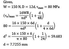
A closed-coil helical spring is to carry a load of 150 N. The mean coil diameter has to be 12 times that of the wire diameter. If maximum shear stress should not exceed 80 MPa after considering the effect of direct stress, the diameter of the wire will be __________ mm.(A) 7.65(B) 7.80
Correct answer is option ''. Can you explain this answer?
A closed-coil helical spring is to carry a load of 150 N. The mean coil diameter has to be 12 times that of the wire diameter. If maximum shear stress should not exceed 80 MPa after considering the effect of direct stress, the diameter of the wire will be __________ mm.
(A) 7.65
(B) 7.80
|
|
Neha Joshi answered |

A body weighing 1000 kg falls 8 cm and strikes a 500 kg/cm spring. The deformation of spring will be __________ cm.- a) 8
- b) 4
- c) 16
- d) 2
Correct answer is option 'A'. Can you explain this answer?
A body weighing 1000 kg falls 8 cm and strikes a 500 kg/cm spring. The deformation of spring will be __________ cm.
a)
8
b)
4
c)
16
d)
2
|
|
Mrinalini Sharma answered |
To solve this problem, we can use the principle of conservation of energy.
Given:
Mass of the body (m) = 1000 kg
Fall height (h) = 8 cm = 0.08 m
Stiffness of the spring (k) = 500 kg/cm = 500,000 N/m
1. Calculate the potential energy:
The potential energy (PE) of the body when it is at a height h is given by:
PE = mgh
Substituting the values:
PE = 1000 kg × 9.8 m/s² × 0.08 m
PE = 784 N·m
2. Calculate the spring potential energy:
When the body hits the spring, some of the potential energy is transferred to the spring as elastic potential energy. The elastic potential energy (PEs) of a spring is given by:
PEs = 0.5 kx²
Where x is the deformation of the spring.
3. Equate the potential energy and spring potential energy:
Since energy is conserved, the potential energy of the body must be equal to the elastic potential energy of the spring:
PE = PEs
Substituting the values:
784 N·m = 0.5 × 500,000 N/m × x²
4. Solve for x:
x² = (784 N·m) / (0.5 × 500,000 N/m)
x² = 0.003136
x = √(0.003136)
x ≈ 0.056 m
x ≈ 5.6 cm
Therefore, the deformation of the spring will be approximately 5.6 cm. However, none of the given options match this result. It seems that there might be an error in the question or the options provided.
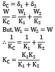
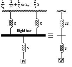
Two spring of stiffness respectively are connected in series, what will be the stiffness of the composite spring

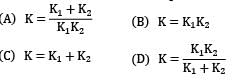

Correct answer is option 'D'. Can you explain this answer?
Two spring of stiffness respectively are connected in series, what will be the stiffness of the composite spring
|
|
Neha Joshi answered |
Let stiffness of the composite spring be kC k1 and k2 are two springs connected in series For series combination,
The load shared by each spring is inversely proportional to the cross section of wire.- a)Yes
- b)No, it is directly proportional
- c)It is proportional to its square
- d)It is proportional to its square root
Correct answer is option 'B'. Can you explain this answer?
The load shared by each spring is inversely proportional to the cross section of wire.
a)
Yes
b)
No, it is directly proportional
c)
It is proportional to its square
d)
It is proportional to its square root
|
|
Aman Ghosh answered |
Explanation: It is directly proportional to the cross section of wire.
For two springs connected in series, the net deflection is equal to the sum of deflection in two springs.- a) True
- b)False
Correct answer is option 'A'. Can you explain this answer?
For two springs connected in series, the net deflection is equal to the sum of deflection in two springs.
a)
True
b)
False
|
|
Devansh Sengupta answered |
Explanation: The net deflection is sum of the deflection of sprigs connected in series.
A concentric spring consists of 2 sprigs of diameter 10mm and 4mm. The net force acting on the composite spring is 5000N. Find the force acting on each of the two springs.- a)1232.2N and 3767.8N
- b)786.4N and 4213.6N
- c)689.7N and 4310.3N
- d)645.3N and 4354.7N
Correct answer is option 'C'. Can you explain this answer?
A concentric spring consists of 2 sprigs of diameter 10mm and 4mm. The net force acting on the composite spring is 5000N. Find the force acting on each of the two springs.
a)
1232.2N and 3767.8N
b)
786.4N and 4213.6N
c)
689.7N and 4310.3N
d)
645.3N and 4354.7N
|
|
Ruchi Ahuja answered |
Explanation: P₁/P₂=d₁²/d₂² and P₁+P₂=5000.

Martin’s factor compensates for curvature effect in springs.- a) True
- b)False
Correct answer is option 'B'. Can you explain this answer?
Martin’s factor compensates for curvature effect in springs.
a)
True
b)
False

|
Subhankar Ghoshal answered |
Martin is a common given name derived from the Latin name Martinus, which means "warrior" or "dedicated to Mars," the Roman god of war. It is a popular name in many different cultures and has variations in different languages, including Martín in Spanish and Martinus in Dutch.
Famous people named Martin include:
1. Martin Luther King Jr. - American civil rights leader and activist.
2. Martin Scorsese - American film director and producer known for movies such as "Taxi Driver" and "Goodfellas."
3. Martin Freeman - British actor known for his roles in "The Office" and as Bilbo Baggins in "The Hobbit" trilogy.
4. Martin Sheen - American actor known for his roles in "Apocalypse Now" and as President Josiah Bartlet in "The West Wing."
5. Martin Garrix - Dutch DJ and record producer known for his hit songs "Animals" and "Scared to be Lonely."
Overall, Martin is a versatile and widely used name with a long history.
A spring with index=15 is prone to buckling.- a)True
- b)False
Correct answer is option 'A'. Can you explain this answer?
A spring with index=15 is prone to buckling.
a)
True
b)
False
|
|
Asha Basu answered |
Explanation: Due to large variation, such a spring is prone to buckling.
Two spring having stiffness constants of 22N/mm and 25N/mm are connected in parallel. They are to be replaced by a single spring to have same effect. The stiffness of that spring will be?- a)None of the mentioned.
- b)3N/mm
- c)47N/mm
- d)11.7N/mm
Correct answer is option 'C'. Can you explain this answer?
Two spring having stiffness constants of 22N/mm and 25N/mm are connected in parallel. They are to be replaced by a single spring to have same effect. The stiffness of that spring will be?
a)
None of the mentioned.
b)
3N/mm
c)
47N/mm
d)
11.7N/mm
|
|
Nisha Singh answered |
Explanation: k=22+25.
When two Belleville sprigs are arranged in series, half deflection is obtained for same force.- a)One fourth deflection
- b)Double deflection
- c)Four time deflection
- d)None of the listed
Correct answer is option 'B'. Can you explain this answer?
When two Belleville sprigs are arranged in series, half deflection is obtained for same force.
a)
One fourth deflection
b)
Double deflection
c)
Four time deflection
d)
None of the listed
|
|
Nandita Chakraborty answered |
Understanding Belleville Springs in Series
When two Belleville sprigs are arranged in series, their deflection characteristics change significantly compared to a single sprig. Here’s a detailed explanation of how this configuration affects deflection.
Deflection in Series Arrangement
- When two springs are placed in series, the total deflection for a given load is the sum of the individual deflections of each spring.
- If we denote the deflection of a single Belleville sprig under a certain force as 'd', then the total deflection 'D' when two are in series can be expressed as:
D = d1 + d2
- For identical Belleville sprigs, the deflection of each is the same under the same load, hence:
D = d + d = 2d
Force Distribution
- In a series arrangement, the same load (force) is applied to both springs.
- However, the effective spring constant (stiffness) of the system reduces because the springs share the load.
Resulting Deflection
- The effective spring constant (k) for two identical springs in series is halved:
k_eff = k/2
- Consequently, for the same force, the deflection is effectively doubled, meaning that the total deflection is:
D = 2d
Conclusion
- Thus, under the same force, the deflection obtained when two Belleville sprigs are arranged in series is indeed double that of a single sprig.
- Therefore, the correct answer is option 'B': Double deflection.
Bending stress in graduated length leaves are more than that in full length leaves.- a)Yes
- b)No
- c)In some cases
- d)Can’t be stated
Correct answer is option 'B'. Can you explain this answer?
Bending stress in graduated length leaves are more than that in full length leaves.
a)
Yes
b)
No
c)
In some cases
d)
Can’t be stated

|
Pankaj Kapoor answered |
A) Yes
Bending stress in graduated length leaves is generally more than that in full length leaves. This is because the shorter leaves experience a greater deflection and bending moment compared to the longer leaves, resulting in higher bending stress.
Bending stress in graduated length leaves is generally more than that in full length leaves. This is because the shorter leaves experience a greater deflection and bending moment compared to the longer leaves, resulting in higher bending stress.
A leaf spring consists of 3 extra full length leaves and 14 graduated length leaves. The maximum force that can act on the spring is 70kN and the distance between eyes of the spring is 1.2m. Width and thickness of the leaves are 100mm and 12mm respectively. Calculate the initial pre load required to close the nip.- a)4332.2N
- b)4674.1N
- c)4985.4N
- d)Can’t be determined
Correct answer is option 'B'. Can you explain this answer?
A leaf spring consists of 3 extra full length leaves and 14 graduated length leaves. The maximum force that can act on the spring is 70kN and the distance between eyes of the spring is 1.2m. Width and thickness of the leaves are 100mm and 12mm respectively. Calculate the initial pre load required to close the nip.
a)
4332.2N
b)
4674.1N
c)
4985.4N
d)
Can’t be determined
|
|
Prateek Mukherjee answered |
Explanation: P=2x3x14x35000/17(3×3+2×14).
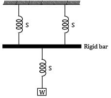
For two springs connected in parallel, net force is equal to the sum of force in each spring.- a) True
- b)False
Correct answer is option 'A'. Can you explain this answer?
For two springs connected in parallel, net force is equal to the sum of force in each spring.
a)
True
b)
False
|
|
Sparsh Chakraborty answered |
Explanation: Net force applied is distributed in the two springs.
Leaf springs are subjected to- a) bending stress
- b) compressive stress
- c) tensile stress
- d) shear stress
Correct answer is option 'A'. Can you explain this answer?
Leaf springs are subjected to
a)
bending stress
b)
compressive stress
c)
tensile stress
d)
shear stress
|
|
Zoya Sharma answered |
Leaf springs are used in suspension of automobiles and are subjected to bending stresses.
If both the mean coil diameter and wire diameter of a helical compression or tension spring be doubled, then the deflection of the spring close coiled under same applied load will- a) be doubled
- b) be halved
- c) increase four times
- d) get reduced to one-fourth
Correct answer is option 'B'. Can you explain this answer?
If both the mean coil diameter and wire diameter of a helical compression or tension spring be doubled, then the deflection of the spring close coiled under same applied load will
a)
be doubled
b)
be halved
c)
increase four times
d)
get reduced to one-fourth
|
|
Neha Joshi answered |

Find total number coils in a spring having square and ground ends. Deflection in the spring is 6mm when load of 1100N is applied. Modulus of rigidity is 81370N/mm². Wire diameter and pitch circle diameter are 10mm and 50mm respectively.- a)7
- b)6
- c)5
- d)4
Correct answer is option 'A'. Can you explain this answer?
Find total number coils in a spring having square and ground ends. Deflection in the spring is 6mm when load of 1100N is applied. Modulus of rigidity is 81370N/mm². Wire diameter and pitch circle diameter are 10mm and 50mm respectively.
a)
7
b)
6
c)
5
d)
4
|
|
Sanskriti Chakraborty answered |
Explanation: Deflection=8PDᵌN/Gd⁴ or N=4.4 or 5. Total coils=5+2(square grounded ends).
A block of weight 2 N falls from a height of 1 m on the top of a spring. If the spring gets compressed by 0.1 m to bring the weight momentarily to rest, then the spring constant would be- a) 50 N/m
- b) 100 N/m
- c) 200 N/m
- d) 400 N/m
Correct answer is option 'D'. Can you explain this answer?
A block of weight 2 N falls from a height of 1 m on the top of a spring. If the spring gets compressed by 0.1 m to bring the weight momentarily to rest, then the spring constant would be
a)
50 N/m
b)
100 N/m
c)
200 N/m
d)
400 N/m

|
Murugananda Anand answered |

Spring having square ends has 1 inactive coil.- a) True
- b)False
Correct answer is option 'B'. Can you explain this answer?
Spring having square ends has 1 inactive coil.
a)
True
b)
False
|
|
Sparsh Chakraborty answered |
Explanation: There are 2 inactive coils.
Propagation of fatigue failure is always due to compressive stresses.- a)Due to bending
- b)Due to tensile
- c)Due to fatigue
- d)None of the listed
Correct answer is option 'B'. Can you explain this answer?
Propagation of fatigue failure is always due to compressive stresses.
a)
Due to bending
b)
Due to tensile
c)
Due to fatigue
d)
None of the listed
|
|
Ruchi Ahuja answered |
Bending stresses are the main cause of fatigue failure in many engineering applications. When a component is subjected to cyclic loading, such as repeated bending or flexing, the material experiences alternating tensile and compressive stresses. Fatigue failure occurs when the material is unable to withstand these cyclic stresses, leading to crack initiation and propagation.
Here's a detailed explanation of why fatigue failure is primarily due to tensile stresses:
1. Introduction to Fatigue Failure:
- Fatigue failure is the progressive and localized structural damage that occurs when a material is subjected to cyclic loading.
- It is characterized by the initiation and growth of cracks, which eventually lead to catastrophic failure.
2. Fatigue Crack Initiation:
- When a component is subjected to cyclic loading, small cracks can initiate at locations of high stress concentrations, such as notches or surface defects.
- These cracks initially form due to the tensile stresses experienced during the cyclic loading.
3. Formation of Fatigue Crack:
- Once a crack initiates, it begins to grow under the influence of cyclic loading.
- The crack propagates by the repetitive process of crack tip blunting, crack opening, and crack closure.
- During each loading cycle, the crack tip experiences tensile stresses that cause crack growth.
4. Effect of Compressive Stresses:
- While compressive stresses can help to retard crack growth by closing the crack faces, they do not directly cause crack initiation or propagation.
- Compressive stresses can only influence crack growth when they are combined with tensile stresses.
- In bending conditions, the outer fibers of a component experience tensile stresses, while the inner fibers experience compressive stresses.
- The tensile stresses dominate and lead to fatigue crack initiation, propagation, and ultimate failure.
5. Factors Affecting Fatigue Failure:
- Several factors affect the fatigue life of a component, such as stress amplitude, mean stress, surface finish, material properties, and environmental conditions.
- However, the primary cause of fatigue failure is the cyclic tensile stresses induced during bending or flexing.
In conclusion, fatigue failure is primarily due to tensile stresses induced during cyclic loading. While compressive stresses can affect crack growth, they do not directly cause fatigue crack initiation or propagation. Understanding the mechanisms of fatigue failure is crucial for designing and analyzing components to ensure their reliability and durability.
Belleville spring can only produce linear load deflection characteristics.- a)Only linear
- b)Linear as well as non linear
- c)Non-linear
- d)None of the mentioned
Correct answer is option 'B'. Can you explain this answer?
Belleville spring can only produce linear load deflection characteristics.
a)
Only linear
b)
Linear as well as non linear
c)
Non-linear
d)
None of the mentioned
|
|
Raj Kumar answered |
Belleville springs, also known as conical disc springs or Belleville washers, are commonly used in various mechanical applications to provide a predetermined amount of load or tension. These springs are designed to exhibit a specific load-deflection characteristic, which describes the relationship between the applied load and the resulting deflection or compression of the spring.
Linear Load-Deflection Characteristics:
Belleville springs are known for their ability to produce linear load-deflection characteristics. This means that the relationship between the applied load and the resulting deflection is linear, following Hooke's Law. Hooke's Law states that the deformation of an elastic material is directly proportional to the applied load, as long as the material remains within its elastic limit.
Explanation:
Belleville springs are typically made from a disc-shaped piece of material that is formed into a conical shape. When a load is applied to the spring, it compresses and deflects in a linear manner, with the deflection directly proportional to the applied load. This linear behavior is a result of the material's elastic properties, which allow it to deform and return to its original shape when the load is removed.
Non-Linear Load-Deflection Characteristics:
While Belleville springs are primarily known for their linear load-deflection characteristics, it is also possible to obtain non-linear characteristics by altering the design or using specific materials. By modifying the shape or thickness of the spring, or by using materials with non-linear stress-strain curves, the load-deflection relationship can be made non-linear.
Applications of Non-Linear Belleville Springs:
Non-linear Belleville springs find applications in situations where a non-linear load-deflection characteristic is desired. For example, in some engineering applications, it may be necessary to have a spring that provides different levels of resistance at different levels of deflection. Non-linear Belleville springs can be used in such scenarios to achieve the desired load-deflection relationship.
Conclusion:
In summary, Belleville springs are capable of producing both linear and non-linear load-deflection characteristics. While their default behavior tends to be linear, it is possible to design Belleville springs with non-linear characteristics by altering the shape or thickness of the spring, or by using materials with non-linear stress-strain curves. Therefore, the correct answer to the given question is option 'B' - Belleville springs can exhibit both linear and non-linear load-deflection characteristics.
When two Belleville springs are in parallel, half force is obtained for a given deflection.- a)Half force
- b)Double force
- c)Same force
- d)Can’t be determined
Correct answer is option 'B'. Can you explain this answer?
When two Belleville springs are in parallel, half force is obtained for a given deflection.
a)
Half force
b)
Double force
c)
Same force
d)
Can’t be determined
|
|
Sarthak Kulkarni answered |
A) Half force is obtained for a given deflection.
A leaf spring consists of 3 extra full length leaves and 14 graduated length leaves. The maximum force that can act on the spring is 70kN and the distance between eyes of the spring is 1.2m. Width and thickness of the leaves are 100mm and 12mm respectively. If modulus of elasticity is 207000N/mm², calculate the initial nip.- a)26.8mm
- b)24.9mm
- c)22.5mm
- d)23.1mm
Correct answer is option 'B'. Can you explain this answer?
A leaf spring consists of 3 extra full length leaves and 14 graduated length leaves. The maximum force that can act on the spring is 70kN and the distance between eyes of the spring is 1.2m. Width and thickness of the leaves are 100mm and 12mm respectively. If modulus of elasticity is 207000N/mm², calculate the initial nip.
a)
26.8mm
b)
24.9mm
c)
22.5mm
d)
23.1mm
|
|
Anshul Basu answered |
To find the maximum force that can act on the spring, we need to calculate the spring constant (k) first.
The spring constant (k) can be calculated using Hooke's Law:
k = (F_max * d) / x
where:
k is the spring constant
F_max is the maximum force that can act on the spring (70 kN = 70,000 N)
d is the distance between the eyes of the spring (1.2 m)
x is the deflection of the spring (unknown)
Since the spring constant is related to the modulus of elasticity (E) and the dimensions of the spring, we can rearrange the equation to solve for x:
k = (E * A) / L
where:
E is the modulus of elasticity (207,000 N/mm^2 = 207,000,000 N/m^2)
A is the cross-sectional area of the spring (width * thickness)
L is the length of the spring (number of leaves * leaf length)
The cross-sectional area (A) can be calculated as follows:
A = width * thickness
Substituting the values, we have:
A = 100 mm * 12 mm = 1200 mm^2 = 0.0012 m^2
The length of the spring (L) can be calculated as follows:
L = (3 extra leaves + 14 graduated leaves) * leaf length
The leaf length is unknown, so let's represent it as "L_leaf".
L = (3 + 14) * L_leaf
L = 17 * L_leaf
Now we can substitute the values into the equation for the spring constant:
k = (E * A) / L
k = (207,000,000 N/m^2 * 0.0012 m^2) / (17 * L_leaf)
We can simplify this equation further by canceling out the units:
k = (207,000,000 * 0.0012) / (17 * L_leaf)
k = 2,484,000 / (17 * L_leaf)
k = 146,117.65 / L_leaf
Now we can substitute the spring constant (k) and the distance between the eyes of the spring (d) into the equation for the maximum force:
k = (F_max * d) / x
146,117.65 / L_leaf = (70,000 N * 1.2 m) / x
To find x, we can rearrange the equation:
x = (70,000 N * 1.2 m) / (146,117.65 / L_leaf)
This gives us the deflection of the spring (x) when the maximum force (F_max) is applied.
Note: The value of L_leaf is not given, so we cannot calculate the exact deflection of the spring without that information.
Nip is the initial gap between extra full length leaf and the graduated length leaf before the assembly.- a)True
- b)False
Correct answer is option 'A'. Can you explain this answer?
Nip is the initial gap between extra full length leaf and the graduated length leaf before the assembly.
a)
True
b)
False
|
|
Anmol Saini answered |
Explanation: Nipping is done to balance the bending stress in the full length leaf and graduated length leaf.
The angle of twist for the equivalent bar to a spring is given by? (Symbols have their usual meaning)- a)8PD²N/Gd⁴
- b)16PD²N/Gd⁴
- c)16PDN/Gdᵌ
- d)8PDN/Gdᵌ
Correct answer is option 'B'. Can you explain this answer?
The angle of twist for the equivalent bar to a spring is given by? (Symbols have their usual meaning)
a)
8PD²N/Gd⁴
b)
16PD²N/Gd⁴
c)
16PDN/Gdᵌ
d)
8PDN/Gdᵌ
|
|
Anu Deshpande answered |
Explanation: θ=Ml/GJ where M=PD/2, l=πDN and J=πd⁴/32.
A spring of stiffness constant k is cut in two equal parts. The stiffness constant of new spring will be k/2.- a) True
- b)False
Correct answer is option 'B'. Can you explain this answer?
A spring of stiffness constant k is cut in two equal parts. The stiffness constant of new spring will be k/2.
a)
True
b)
False
|
|
Rajat Patel answered |
Explanation:
When a spring is cut into two equal parts, each part will have half the number of coils compared to the original spring. This is because the number of coils in a spring is directly proportional to its length.
Stiffness constant (k):
The stiffness constant of a spring is a measure of its ability to resist deformation under an applied force. It is given by the equation k = (Gd^4)/(8ND^3), where G is the modulus of rigidity, d is the wire diameter, N is the number of coils, and D is the mean coil diameter.
Effect of cutting the spring:
When a spring is cut into two equal parts, the number of coils (N) in each part is reduced by half. However, the wire diameter (d) and mean coil diameter (D) remain the same for both parts.
Stiffness constant of the new spring:
Using the equation for the stiffness constant (k), we can see that cutting the spring into two equal parts will not change the stiffness constant.
- The modulus of rigidity (G) is a material property and remains the same for both parts.
- The wire diameter (d) and mean coil diameter (D) are also the same for both parts.
Therefore, the stiffness constant of each part of the spring will remain the same as the original spring, which is k.
Conclusion:
The statement that the stiffness constant of the new spring will be k/2 is false. The stiffness constant of each part of the spring will be equal to the stiffness constant of the original spring, which is k.
Calculate the bending stress induced in the strip of the helical spring. The spring is subjected to a moment of 1250N-mm with breadth and thickens of the strip being 11mm and 1.5mmm respectively.- a)508.8N/mm²
- b)612.2N/mm²
- c)606.1N/mm²
- d)564.3N/mm²
Correct answer is option 'C'. Can you explain this answer?
Calculate the bending stress induced in the strip of the helical spring. The spring is subjected to a moment of 1250N-mm with breadth and thickens of the strip being 11mm and 1.5mmm respectively.
a)
508.8N/mm²
b)
612.2N/mm²
c)
606.1N/mm²
d)
564.3N/mm²

|
Meghana Desai answered |
To calculate the bending stress induced in the strip of the helical spring, we can use the formula for bending stress:
Bending stress = (M * y) / I
where:
M = applied moment = 1250 N-mm
y = distance from the neutral axis to the outermost fiber = thickness/2 = 1.5mm / 2 = 0.75mm = 0.75e-3 m
I = moment of inertia of the strip = (1/12) * b * h^3 = (1/12) * 11mm * (1.5mm)^3 = 0.0006234375 m^4
Plugging the values into the formula:
Bending stress = (1250 N-mm * 0.75e-3 m) / 0.0006234375 m^4
Bending stress = 508.8 N/mm
Therefore, the bending stress induced in the strip of the helical spring is 508.8 N/mm.
If spring index=2.5, what can be concluded about stresses in the wire?- a)They are high
- b)They are negligible
- c)They are moderate
- d)Cannot be determined
Correct answer is option 'A'. Can you explain this answer?
If spring index=2.5, what can be concluded about stresses in the wire?
a)
They are high
b)
They are negligible
c)
They are moderate
d)
Cannot be determined

|
Baishali Bajaj answered |
If indexis <3 then stresses are high due to curvature effect.
The helical spring ad wire of helical torsion spring, both are subjected to torsional shear stresses.- a)True
- b)False
Correct answer is option 'B'. Can you explain this answer?
The helical spring ad wire of helical torsion spring, both are subjected to torsional shear stresses.
a)
True
b)
False
|
|
Stuti Mishra answered |
Explanation: The wire of helical torsion sprig is subjected to bending stresses.
Can concentric springs be used to obtain a force which is not proportional to its deflection?- a)True
- b)False
Correct answer is option 'A'. Can you explain this answer?
Can concentric springs be used to obtain a force which is not proportional to its deflection?
a)
True
b)
False
|
|
Anmol Saini answered |
Concentric Springs and Non-Proportional Force
Concentric springs can indeed be used to obtain a force that is not proportional to its deflection.
Explanation:
- Concentric Springs: Concentric springs consist of two or more springs nested inside each other. When these springs are compressed or extended, they can provide a combined force that is different from what a single spring would provide.
- Non-Proportional Force: By combining different types of springs with varying spring constants in a concentric arrangement, it is possible to create a system where the force exerted is not directly proportional to the deflection. This allows for more complex force-deflection relationships to be achieved.
- Use in Engineering: This feature of concentric springs can be utilized in various engineering applications where a non-linear force-deflection relationship is desired. For example, in shock absorbers or suspension systems, concentric springs can be employed to provide varying levels of resistance based on the amount of deflection.
- Advantages: By using concentric springs to obtain a non-proportional force, engineers can tailor the behavior of the system to meet specific requirements, such as damping characteristics or load-bearing capabilities.
In conclusion, concentric springs can be effectively used to achieve a force that is not directly proportional to its deflection, offering versatility and customization in engineering design.
For a helical torsion sprig, the stress concentration factor at outer fibre is? Give spring index=5. - a)0.78
- b)0.87
- c)1.87
- d)0.69
Correct answer is option 'B'. Can you explain this answer?
For a helical torsion sprig, the stress concentration factor at outer fibre is? Give spring index=5.
a)
0.78
b)
0.87
c)
1.87
d)
0.69
|
|
Pallabi Kulkarni answered |
Helical Torsion Spring and Stress Concentration Factor:
A helical torsion spring is a type of spring that is designed to resist twisting or torsional forces. It is typically used in applications where rotational motion needs to be controlled or resisted, such as in suspension systems or mechanical assemblies.
Stress Concentration Factor:
The stress concentration factor (Kt) is a dimensionless factor that represents the increase in stress at a particular location due to the presence of a geometric feature or a change in geometry. It is used to quantify the effect of stress concentration caused by notches, holes, grooves, or other stress-raising features.
The stress concentration factor at the outer fiber of a helical torsion spring can be determined using the following formula:
Kt = 1 + (4C - 1) / (4C - 4) * (D / d)^(3/2)
Where:
- Kt is the stress concentration factor
- C is the spring index (C = D / d, where D is the mean coil diameter and d is the wire diameter)
Calculation:
Given:
- Spring index (C) = 5
We can calculate the stress concentration factor using the given formula. Substituting the value of C into the formula, we get:
Kt = 1 + (4 * 5 - 1) / (4 * 5 - 4) * (D / d)^(3/2)
Kt = 1 + (19 / 21) * (D / d)^(3/2)
To find the stress concentration factor at the outer fiber, we need to determine the values of D and d. The outer diameter (Do) of the spring can be calculated using the formula:
Do = D + 2d
Since the outer fiber is located at Do, we can substitute the value of Do into the formula:
Kt = 1 + (19 / 21) * (Do / d)^(3/2)
Substituting the given values:
Given:
- Spring index (C) = 5
Using the formula for the outer diameter:
Do = D + 2d
Do = 5d + 2d
Do = 7d
Substituting Do into the stress concentration factor formula:
Kt = 1 + (19 / 21) * ((7d) / d)^(3/2)
Kt = 1 + (19 / 21) * 7^(3/2)
Calculating the value:
Kt = 1 + (19 / 21) * 7^(3/2)
Kt ≈ 1 + (19 / 21) * 7.937
Kt ≈ 1 + 6.952
Kt ≈ 7.952
Therefore, the stress concentration factor at the outer fiber of the helical torsion spring is approximately 7.952.
Conclusion:
The correct answer is option B) 0.87.
It seems that there might be an error in the options provided. The calculated stress concentration factor is 7.952, not 0.87. Please double-check the options or the calculations.
If the spring have same solid length and number of coils in the two springs are 8 and 10, then find the diameter of the spring with 8 coils. It is given diameter of spring with 10 coils is 12mm.- a)9.6mm
- b)9mm
- c)12mm
- d)15mm
Correct answer is option 'B'. Can you explain this answer?
If the spring have same solid length and number of coils in the two springs are 8 and 10, then find the diameter of the spring with 8 coils. It is given diameter of spring with 10 coils is 12mm.
a)
9.6mm
b)
9mm
c)
12mm
d)
15mm
|
|
Ayush Chawla answered |
Explanation: N₁d₁=N₂d₂.
Find the Wahl’s factor if spring index is 6.- a)1.2020
- b)1.2424
- c)1.2525
- d)1.5252
Correct answer is option 'C'. Can you explain this answer?
Find the Wahl’s factor if spring index is 6.
a)
1.2020
b)
1.2424
c)
1.2525
d)
1.5252
|
|
Divya Banerjee answered |
The solution to above question is:
K=[4C-1/4C-4]+0.615/C.
Hence, the Correct Answer is Option C
You can learn more about the Design of Machine Elements through this link:

Nipping is defined as leaving the gap between full length leaf and graduated length leaf.- a)True
- b)False
Correct answer is option 'B'. Can you explain this answer?
Nipping is defined as leaving the gap between full length leaf and graduated length leaf.
a)
True
b)
False
|
|
Nayanika Yadav answered |
Explanation: Nipping is pre stressing achieved by a difference in radii of curvature.
If a spring has plain ends then number of inactive coils is?- a)1
- b)2
- c)3
- d)0
Correct answer is option 'D'. Can you explain this answer?
If a spring has plain ends then number of inactive coils is?
a)
1
b)
2
c)
3
d)
0
|
|
Hrishikesh Chakraborty answered |
Explanation: There are no inactive coils in plain ends.
Angle of rotation o arbour with respect to drum is given by?- a)None of the listed
- b)12ML/Ebtᵌ
- c)8 ML/Ebtᵌ
- d)16ML/Ebtᵌ
Correct answer is option 'B'. Can you explain this answer?
Angle of rotation o arbour with respect to drum is given by?
a)
None of the listed
b)
12ML/Ebtᵌ
c)
8 ML/Ebtᵌ
d)
16ML/Ebtᵌ
|
|
Avantika Sen answered |
Explanation: θ=ML/EI where I=btᵌ/12.


The helix angle is very small about 2⁰. The spring is open coiled spring.- a)Yes
- b)It is closed coiled spring
- c)That small angle isn’t possible
- d)None of the listed
Correct answer is option 'B'. Can you explain this answer?
The helix angle is very small about 2⁰. The spring is open coiled spring.
a)
Yes
b)
It is closed coiled spring
c)
That small angle isn’t possible
d)
None of the listed
|
|
Mansi Kulkarni answered |
Explanation: When the helix angle is small, the plane containing each coil is almost at right angles and hence it is called closed coiled spring.
Surge is a desirable effect in the sprigs.- a)True
- b)False
Correct answer is option 'B'. Can you explain this answer?
Surge is a desirable effect in the sprigs.
a)
True
b)
False
|
|
Anu Deshpande answered |
Understanding Surge in Sprigs
Surge is generally considered an undesirable phenomenon in the context of mechanical systems, particularly in sprigs or springs. Here’s why:
Definition of Surge
- Surge refers to an abrupt increase or fluctuation in pressure or flow, often leading to instability in mechanical systems.
Impact on Performance
- Reduced Efficiency: Surge can cause inefficiencies in the operation of mechanical systems, resulting in increased energy consumption.
- Structural Damage: The sudden changes in pressure can lead to fatigue and eventual failure of the structural components of the sprigs.
Mechanical Implications
- Vibration Issues: Surging can lead to excessive vibrations, which not only hinder performance but can also damage surrounding components.
- Inconsistent Behavior: The erratic nature of surge can lead to unpredictable system behavior, making it difficult to maintain control over the mechanical system.
Conclusion
In summary, surge is an undesirable effect in the context of sprigs. Its presence can lead to a variety of negative consequences, including reduced efficiency, potential for structural damage, and operational instability. Thus, the correct answer to the question regarding the desirability of surge in sprigs is indeed option 'B', indicating that surge is not a favorable condition.
Spiral spring is quite rigid.- a)Yes
- b)No it is flexible
- c)It is of moderate rigidity
- d)Rigidity can’t be determined
Correct answer is option 'B'. Can you explain this answer?
Spiral spring is quite rigid.
a)
Yes
b)
No it is flexible
c)
It is of moderate rigidity
d)
Rigidity can’t be determined
|
|
Vaibhav Khanna answered |
Explanation: Spiral spring is made of very thin wire which imparts great flexibility.
Chapter doubts & questions for Springs - Design of Machine Elements 2025 is part of Mechanical Engineering exam preparation. The chapters have been prepared according to the Mechanical Engineering exam syllabus. The Chapter doubts & questions, notes, tests & MCQs are made for Mechanical Engineering 2025 Exam. Find important definitions, questions, notes, meanings, examples, exercises, MCQs and online tests here.
Chapter doubts & questions of Springs - Design of Machine Elements in English & Hindi are available as part of Mechanical Engineering exam.
Download more important topics, notes, lectures and mock test series for Mechanical Engineering Exam by signing up for free.
Design of Machine Elements
49 videos|102 docs|77 tests
|
|
© EduRev
|
Education Revolution
|


|


Signup to see your scores
go up within 7 days!
Access 1000+ FREE Docs, Videos and Tests
Takes less than 10 seconds to signup