


Electrical Engineering (EE) Exam > Electrical Engineering (EE) Questions > A full-wave rectifier uses 2 diodes. The inte... Start Learning for Free
A full-wave rectifier uses 2 diodes. The internal resistance of each diode is 20 Ω. The transformer RMS secondary voltage from centre tap to each end of the secondary is 50 V and the load resistance is 980 Ω. Mean load current will be
- a)45 A
- b)4.5 A
- c)45 mA
- d)45 μA
Correct answer is option 'C'. Can you explain this answer?

Most Upvoted Answer
A full-wave rectifier uses 2 diodes. The internal resistance of each d...
Concept:
Center tapped full wave rectifier:
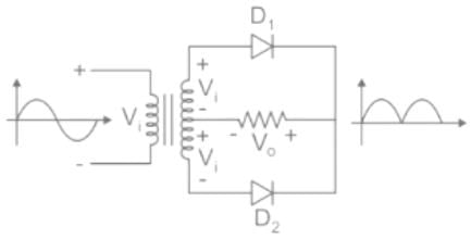
- The Center tapped full-wave rectifier is a device used to convert the AC input voltage into DC voltage at the output terminals.
- It employs a transformer with the secondary winding tapped at the center point. And it uses only two diodes, which are connected to the opposite ends of a center-tapped transformer as shown in the figure below.
- The center tap is usually considered as the ground point or the zero voltage reference point.
Analysis: The DC output voltage or average output voltage can be calculated as follows,

V0 = 2Vm / π
Now we can calculate the average or mean current of load by dividing the average load voltage by load resistance RL. Therefore mean load current is given by
I0 = V0 / RL
If the internal resistance of the diode is given in that case mean load current I0 = V0 / (RL + r)
Where r = internal resistance of the diode.
Calculation:
Given that
Rms value of supply voltage V = 50 V
The internal resistance of diode r = 20 Ω
The load resistance RL = 980 Ω
Maximum voltage on the secondary side Vm = √2 V = √2 × 50 = 70.7 V
Average or DC output voltage V0 = (2 × 70.7) / π = 45 V
Average or mean load current is
I0 = V0 / (RL + r) = 45 /(980 + 20) = 45 mA
Free Test
FREE
| Start Free Test |
Community Answer
A full-wave rectifier uses 2 diodes. The internal resistance of each d...
Ohms. When a 120V AC signal is applied to the rectifier, calculate the voltage across the load resistor if RL = 100 ohms.
To solve this problem, we need to understand the operation of a full-wave rectifier. A full-wave rectifier converts an AC signal to a pulsating DC signal. It uses two diodes to rectify both the positive and negative cycles of the AC signal.
In this case, the input voltage is 120V AC. The diodes have an internal resistance of 20 ohms each, and the load resistor RL is 100 ohms.
During the positive half cycle of the AC signal, diode D1 will be forward-biased and conduct current, while diode D2 will be reverse-biased and block current flow. The voltage across the load resistor will be the difference between the input voltage and the voltage drop across the diode D1.
The voltage drop across each diode can be approximated as the voltage across the load resistor divided by two, since the two diodes share the load current equally.
Voltage drop across each diode = (Voltage across load resistor) / 2
During the negative half cycle of the AC signal, diode D1 will be reverse-biased and block current flow, while diode D2 will be forward-biased and conduct current. The voltage across the load resistor will be the difference between the input voltage and the voltage drop across the diode D2.
Again, the voltage drop across each diode can be approximated as the voltage across the load resistor divided by two.
Voltage drop across each diode = (Voltage across load resistor) / 2
To find the voltage across the load resistor, we need to calculate the voltage drop across each diode during both the positive and negative half cycles of the AC signal.
Voltage drop across each diode = (Voltage across load resistor) / 2
= (120V - 2 * 20 ohms * I) / 2
= (120V - 40 ohms * I) / 2
where I is the load current.
Since the load current is the same during both half cycles of the AC signal, we can equate the voltage drop across each diode during the positive half cycle to the voltage drop across each diode during the negative half cycle.
(120V - 40 ohms * I) / 2 = (120V - 40 ohms * I) / 2
Simplifying this equation, we get:
120V - 40 ohms * I = 120V - 40 ohms * I
The load current cancels out, and we are left with:
120V = 120V
This equation holds true, indicating that the voltage across the load resistor is equal to the input voltage of 120V AC.
Therefore, the voltage across the load resistor is 120V.
 | Explore Courses for Electrical Engineering (EE) exam |
Top Courses for Electrical Engineering (EE)View all


Top Courses for Electrical Engineering (EE)
Question Description
A full-wave rectifier uses 2 diodes. The internal resistance of each diode is 20 Ω. The transformer RMS secondary voltage from centre tap to each end of the secondary is 50 V and the load resistance is 980 Ω. Mean load current will bea)45 Ab)4.5 Ac)45 mAd)45 μACorrect answer is option 'C'. Can you explain this answer? for Electrical Engineering (EE) 2026 is part of Electrical Engineering (EE) preparation. The Question and answers have been prepared according to the Electrical Engineering (EE) exam syllabus. Information about A full-wave rectifier uses 2 diodes. The internal resistance of each diode is 20 Ω. The transformer RMS secondary voltage from centre tap to each end of the secondary is 50 V and the load resistance is 980 Ω. Mean load current will bea)45 Ab)4.5 Ac)45 mAd)45 μACorrect answer is option 'C'. Can you explain this answer? covers all topics & solutions for Electrical Engineering (EE) 2026 Exam. Find important definitions, questions, meanings, examples, exercises and tests below for A full-wave rectifier uses 2 diodes. The internal resistance of each diode is 20 Ω. The transformer RMS secondary voltage from centre tap to each end of the secondary is 50 V and the load resistance is 980 Ω. Mean load current will bea)45 Ab)4.5 Ac)45 mAd)45 μACorrect answer is option 'C'. Can you explain this answer?.
A full-wave rectifier uses 2 diodes. The internal resistance of each diode is 20 Ω. The transformer RMS secondary voltage from centre tap to each end of the secondary is 50 V and the load resistance is 980 Ω. Mean load current will bea)45 Ab)4.5 Ac)45 mAd)45 μACorrect answer is option 'C'. Can you explain this answer? for Electrical Engineering (EE) 2026 is part of Electrical Engineering (EE) preparation. The Question and answers have been prepared according to the Electrical Engineering (EE) exam syllabus. Information about A full-wave rectifier uses 2 diodes. The internal resistance of each diode is 20 Ω. The transformer RMS secondary voltage from centre tap to each end of the secondary is 50 V and the load resistance is 980 Ω. Mean load current will bea)45 Ab)4.5 Ac)45 mAd)45 μACorrect answer is option 'C'. Can you explain this answer? covers all topics & solutions for Electrical Engineering (EE) 2026 Exam. Find important definitions, questions, meanings, examples, exercises and tests below for A full-wave rectifier uses 2 diodes. The internal resistance of each diode is 20 Ω. The transformer RMS secondary voltage from centre tap to each end of the secondary is 50 V and the load resistance is 980 Ω. Mean load current will bea)45 Ab)4.5 Ac)45 mAd)45 μACorrect answer is option 'C'. Can you explain this answer?.
Solutions for A full-wave rectifier uses 2 diodes. The internal resistance of each diode is 20 Ω. The transformer RMS secondary voltage from centre tap to each end of the secondary is 50 V and the load resistance is 980 Ω. Mean load current will bea)45 Ab)4.5 Ac)45 mAd)45 μACorrect answer is option 'C'. Can you explain this answer? in English & in Hindi are available as part of our courses for Electrical Engineering (EE). Download more important topics, notes, lectures and mock test series for Electrical Engineering (EE) Exam by signing up for free.
Here you can find the meaning of A full-wave rectifier uses 2 diodes. The internal resistance of each diode is 20 Ω. The transformer RMS secondary voltage from centre tap to each end of the secondary is 50 V and the load resistance is 980 Ω. Mean load current will bea)45 Ab)4.5 Ac)45 mAd)45 μACorrect answer is option 'C'. Can you explain this answer? defined & explained in the simplest way possible. Besides giving the explanation of A full-wave rectifier uses 2 diodes. The internal resistance of each diode is 20 Ω. The transformer RMS secondary voltage from centre tap to each end of the secondary is 50 V and the load resistance is 980 Ω. Mean load current will bea)45 Ab)4.5 Ac)45 mAd)45 μACorrect answer is option 'C'. Can you explain this answer?, a detailed solution for A full-wave rectifier uses 2 diodes. The internal resistance of each diode is 20 Ω. The transformer RMS secondary voltage from centre tap to each end of the secondary is 50 V and the load resistance is 980 Ω. Mean load current will bea)45 Ab)4.5 Ac)45 mAd)45 μACorrect answer is option 'C'. Can you explain this answer? has been provided alongside types of A full-wave rectifier uses 2 diodes. The internal resistance of each diode is 20 Ω. The transformer RMS secondary voltage from centre tap to each end of the secondary is 50 V and the load resistance is 980 Ω. Mean load current will bea)45 Ab)4.5 Ac)45 mAd)45 μACorrect answer is option 'C'. Can you explain this answer? theory, EduRev gives you an ample number of questions to practice A full-wave rectifier uses 2 diodes. The internal resistance of each diode is 20 Ω. The transformer RMS secondary voltage from centre tap to each end of the secondary is 50 V and the load resistance is 980 Ω. Mean load current will bea)45 Ab)4.5 Ac)45 mAd)45 μACorrect answer is option 'C'. Can you explain this answer? tests, examples and also practice Electrical Engineering (EE) tests.
| Explore Courses for Electrical Engineering (EE) exam |
Top Courses for Electrical Engineering (EE)
Explore Courses
Signup for Free!
Signup to see your scores go up within 7 days! Learn & Practice with 1000+ FREE Notes, Videos & Tests.


