


Electrical Engineering (EE) Exam > Electrical Engineering (EE) Questions > The circuit diagram shown here corresponds to... Start Learning for Free
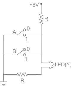
The circuit diagram shown here corresponds to the logic gate
- a)OR
- b)NAND
- c)NOR
- d)AND
Correct answer is option 'C'. Can you explain this answer?

Verified Answer
The circuit diagram shown here corresponds to the logic gatea)ORb)NAND...
CONCEPT:
- OR gate - The OR gate is defined as the gate in which if one of the inputs is true then the result will also true.
- AND gate - The AND gate is defined as the gate in which if one of the inputs is false then the result will also false.
- NOT gate - The NOT gate is defined as the output attains state 1 if and only if the input does not attain state 1.
- NOR gate - NOR gate is defined as it is the combination of NOT and OR gate.
CALCULATION:
Let us the different cases.
Case I - When A = 0, B = 0
The LED will glow.
Therefore, Y = 1
Case II - When A = 1, B = 0
The LED will not glow.
Therefore, Y = 0
Case III - When A = 0, B = 1
The LED will not glow.
Therefore, Y = 0
Case IV - When A = 1, B = 1
The LED will glow.
Therefore, Y = 0
The truth table is written as;
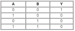
Here we see the results it will show the nature of NOR.
Hence, option 3) is the correct answer.
Let us the different cases.
Case I - When A = 0, B = 0
The LED will glow.
Therefore, Y = 1
Case II - When A = 1, B = 0
The LED will not glow.
Therefore, Y = 0
Case III - When A = 0, B = 1
The LED will not glow.
Therefore, Y = 0
Case IV - When A = 1, B = 1
The LED will glow.
Therefore, Y = 0
The truth table is written as;
Here we see the results it will show the nature of NOR.
Hence, option 3) is the correct answer.
Most Upvoted Answer
The circuit diagram shown here corresponds to the logic gatea)ORb)NAND...
CONCEPT:
- OR gate - The OR gate is defined as the gate in which if one of the inputs is true then the result will also true.
- AND gate - The AND gate is defined as the gate in which if one of the inputs is false then the result will also false.
- NOT gate - The NOT gate is defined as the output attains state 1 if and only if the input does not attain state 1.
- NOR gate - NOR gate is defined as it is the combination of NOT and OR gate.
CALCULATION:
Let us the different cases.
Case I - When A = 0, B = 0
The LED will glow.
Therefore, Y = 1
Case II - When A = 1, B = 0
The LED will not glow.
Therefore, Y = 0
Case III - When A = 0, B = 1
The LED will not glow.
Therefore, Y = 0
Case IV - When A = 1, B = 1
The LED will glow.
Therefore, Y = 0
The truth table is written as;
Here we see the results it will show the nature of NOR.
Hence, option 3) is the correct answer.
 | Explore Courses for Electrical Engineering (EE) exam |
Top Courses for Electrical Engineering (EE)View all


Top Courses for Electrical Engineering (EE)
Question Description
The circuit diagram shown here corresponds to the logic gatea)ORb)NANDc)NORd)ANDCorrect answer is option 'C'. Can you explain this answer? for Electrical Engineering (EE) 2026 is part of Electrical Engineering (EE) preparation. The Question and answers have been prepared according to the Electrical Engineering (EE) exam syllabus. Information about The circuit diagram shown here corresponds to the logic gatea)ORb)NANDc)NORd)ANDCorrect answer is option 'C'. Can you explain this answer? covers all topics & solutions for Electrical Engineering (EE) 2026 Exam. Find important definitions, questions, meanings, examples, exercises and tests below for The circuit diagram shown here corresponds to the logic gatea)ORb)NANDc)NORd)ANDCorrect answer is option 'C'. Can you explain this answer?.
The circuit diagram shown here corresponds to the logic gatea)ORb)NANDc)NORd)ANDCorrect answer is option 'C'. Can you explain this answer? for Electrical Engineering (EE) 2026 is part of Electrical Engineering (EE) preparation. The Question and answers have been prepared according to the Electrical Engineering (EE) exam syllabus. Information about The circuit diagram shown here corresponds to the logic gatea)ORb)NANDc)NORd)ANDCorrect answer is option 'C'. Can you explain this answer? covers all topics & solutions for Electrical Engineering (EE) 2026 Exam. Find important definitions, questions, meanings, examples, exercises and tests below for The circuit diagram shown here corresponds to the logic gatea)ORb)NANDc)NORd)ANDCorrect answer is option 'C'. Can you explain this answer?.
Solutions for The circuit diagram shown here corresponds to the logic gatea)ORb)NANDc)NORd)ANDCorrect answer is option 'C'. Can you explain this answer? in English & in Hindi are available as part of our courses for Electrical Engineering (EE). Download more important topics, notes, lectures and mock test series for Electrical Engineering (EE) Exam by signing up for free.
Here you can find the meaning of The circuit diagram shown here corresponds to the logic gatea)ORb)NANDc)NORd)ANDCorrect answer is option 'C'. Can you explain this answer? defined & explained in the simplest way possible. Besides giving the explanation of The circuit diagram shown here corresponds to the logic gatea)ORb)NANDc)NORd)ANDCorrect answer is option 'C'. Can you explain this answer?, a detailed solution for The circuit diagram shown here corresponds to the logic gatea)ORb)NANDc)NORd)ANDCorrect answer is option 'C'. Can you explain this answer? has been provided alongside types of The circuit diagram shown here corresponds to the logic gatea)ORb)NANDc)NORd)ANDCorrect answer is option 'C'. Can you explain this answer? theory, EduRev gives you an ample number of questions to practice The circuit diagram shown here corresponds to the logic gatea)ORb)NANDc)NORd)ANDCorrect answer is option 'C'. Can you explain this answer? tests, examples and also practice Electrical Engineering (EE) tests.
| Explore Courses for Electrical Engineering (EE) exam |
Top Courses for Electrical Engineering (EE)
Explore Courses
Signup for Free!
Signup to see your scores go up within 7 days! Learn & Practice with 1000+ FREE Notes, Videos & Tests.


