Electricity Class 10 Notes Science Chapter 11

What is Electricity?
Electricity is a fundamental form of energy resulting from the movement of electric charges. It is characterized by the flow of electrons through conductors such as wires.

- Electricity powers various devices and systems, enabling them to perform functions like generating light, producing heat, and operating machinery.
- It is a crucial aspect of modern life and technology, with applications ranging from powering homes and appliances to driving electronic devices and industrial processes.
What is an Electric Charge?
Charge is a fundamental particle in an atom. It may be positive or negative. Electric Charges: Positive and Negative
- Like charges repel each other.
- Unlike charges attract each other.
- Coulomb (C): S. I. unit of charge
- 1 Coulomb charge = Charge present on approx. 6 × 10¹⁸ electrons
- Charge on 1 electron = Negative charge of 1.6 × 10⁻¹⁹ C
i.e. Q = ne
Where, Q = Charge (total)
n = No. of electrons
e = Charge on 1 electron
Electric Current and Circuit
Electric current is important because it powers technology, helps keep us safe, and makes life more convenient. It also helps distribute energy where it’s needed.
Circuits, which are the pathways that control the flow of electric current, are very important too. They are used in electronics, medical devices, transportation, research, and efforts to protect the environment. Circuits are essential to modern life, affecting almost everything we do every day.
What is an Electric Current?
Electric Current (I) is the flow of electric charge through a conductor, such as a wire.
Current = Charge/Time or,
I = Q/T
 Electric Current is the rate of flow of Charge
S. I. unit of current = Ampere (A). An ampere is a unit that measures the rate of electron flow or current in an electrical conductor. One ampere of current represents one coulomb of electrical charge (6.24 x 10¹⁸ charge carriers) moving past a specific point in one second.
⇒ 1 A = 1 Cs-1
⇒ 1 mA = 10-3 A
⇒ 1 µA = 10-6 A
- Current is measured by an Ammeter. Its symbol is

- The ammeter has low resistance and is always connected in series.
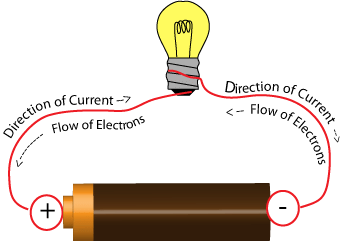
- The direction of current is taken opposite to the flow of electrons as electrons were not known at the time when the phenomenon of electricity was discovered first, and the current was considered to be a flow of positive charge.
Electric Potential and Potential Difference
Electric potential and potential difference are fundamental concepts in the field of electricity and electromagnetism. They are used in various ways, both in theoretical understanding and practical applications.
What is Electric Potential?
- Electric potential is the work done to carry a unit's positive charge from infinity to a point.
- If W is the work done and q is the charge, then electric potential:
V=W/q - The SI unit of electric potential is Volts (V).
What is the Potential Difference?
- A potential difference is that work is done to move a unit charge from one point to another.
V = W/Q

What is the meaning of the 1-volt potential difference?
- S. I. unit of Potential difference is Volt (V)
1 V = 1 JC-1 - When 1-joule work is done carrying one Coulomb charge, then the potential difference is called 1 volt.
- Voltmeter: An instrument used to measure the potential difference. It has high resistance and is always connected in parallel. Symbol is:

- Current always flows from higher potential to lower potential.
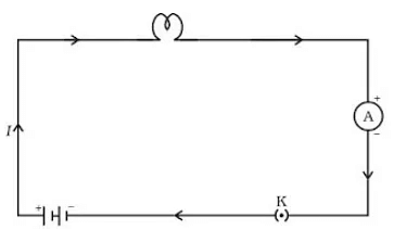
What is an Electric Circuit?
An electric circuit is a closed loop or pathway.It allows electric current to flow through various components.
 Electric Circuit
- Components can include wires, switches, resistors, and energy sources.
- Electrons typically move through conductors, creating the flow of electric current.
- To maintain current flow, the circuit must be closed without interruptions.
- Used in various applications, from lighting to powering electronic devices.
Circuit Diagram
A circuit diagram is a graphical representation of an electric circuit. In this diagram, various components of the circuit, such as cells (or batteries), plug keys, electrical components, and connecting wires, are symbolically represented using conventional symbols.

- These symbols are standardized and commonly used to simplify the visual representation of complex circuits, making it easier for engineers, technicians, and students to understand and work with electrical circuits.
- Circuit components are often represented by symbols in schematic diagrams.
Symbols of Some Commonly Used Components in Circuit
Ohm’s Law
Ohm's Law States that Potential difference across the two points of a metallic conductor is directly proportional to current passing through the circuit provided that temperature remains constant.

- Mathematical expression for Ohm’s law
V ∝ I
⇒ V = IR - R is a constant called resistance for a given metal.

V-I graph for Ohm’s law
- Resistance (R): It is the property of a conductor to resist the flow of charges through it.
- Ohm (Ω): S. I. unit of resistance.
- 1 ohm = 1 volt/1ampere.
When a potential difference is 1 V and the current through the circuit is 1 A, then the resistance is 1 ohm. - Rheostat: Variable resistance is a component used to regulate current without changing the source of voltage.
Factors on which the Resistance of a Conductor depends
Resistance of a uniform metallic conductor is:
(i) directly proportional to the length of conductor,
(ii) inversely proportional to the area of cross-section,
(iii) directly proportional to the temperature and
(iv) depend on nature of material.
What is Resistivity (P)?
Resistivity is defined as the resistance offered by a cube of a material of side 1m when current flows perpendicular to its opposite faces.

- S.I. unit of Resistivity is ohm-metre (Ωm).
- Resistivity does not change with a change in length or area of cross-section, but it changes with a change in temperature.
- The range of resistivity of metals and alloys is 10-8 to 10-6 Ωm.
- The range of resistivity of insulators is 1012 to 1017 Ωm.
- The resistivity of the alloy is generally higher than that of its constituent metals.
- Alloys do not oxidize (burn) readily at high temperatures, so they are commonly used in electrical heating devices.
- Copper and aluminium are used for electrical transmission lines as they have low resistivity.
Resistors in Series
When two or more resistors are connected end to end, the arrangement is called series combination.

Total/resultant/overall/effective resistance in series
Rs = R1 + R2 + R3
- Current through each resistor is same.
- Equivalent resistance is larger than the largest individual resistance.
- Total voltage = Sum of voltage drops
V = V1 + V2 + V3
Voltage across each resistor
- V1 = IR1
- V2 = IR2 [V1 + V2 + V3 = V]
- V3 = IR3V = IR
⇒ V = IR1 + IR2 + IR3
∝ IR = I(R1 + R2 + R3)
∝ R = R1 + R2 + R3
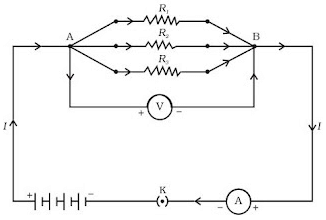
Resistors in Parallel
When multiple resistors are connected in parallel in an electrical circuit, they are arranged so that both ends of each resistor are connected to the same two points, forming multiple paths for current flow.
 Resisters in Parallel
- The voltage across each resistor is the same and equal to the applied voltage.
- The total current is equal to the sum of currents through the individual resistances.
I = I1 + I2 + I3
⇒ V/R = V/R1 + V/R2 + V/R3 - The reciprocal of equivalent resistance is equal to the sum of reciprocals of individual resistances.
1/Rp = 1/R1 + 1/R2 + 1/R3 - Equivalent resistance is less than the value of the smallest individual resistance in the combination.
Advantages of Parallel Combination over Series Combination
(i) In a series circuit, when one component fails, the circuit is broken, and none of the components works.
(ii) Different appliances have different current requirements. This cannot be satisfied in series as the current remains the same.
(iii) The total resistance in a parallel circuit is decreased.
Heating Effect of Electric Current:
If an electric circuit is purely resistive, the source of energy continually gets dissipated entirely in the form of heat. This is known as the heating effect of electric current.
As E = P×T ∝ VIt {E = H}
Heat produced, H = VIt {V = IR}
Or, Heat produced, H = I2Rt
Practical Applications of Heating Effect of Electric Current
The heating effect of electric current, also known as Joule heating, is a fundamental concept in physics and electrical engineering. It's the phenomenon where electrical energy is converted into heat energy when current flows through a conductor with resistance. This heating effect has numerous practical applications in various fields.
 Uses of Heating Effect of Electric Current
Joule’s Law of Heating Effect of Electric Current
It states that the heat produced in a resistor is (i) directly proportional to the square of current, H ∝ I2
- It is directly proportional to resistance for a given current, H ∝ R
- It is directly proportional to the time for which current flows through the conductor, H ∝ t.
So, H = I2Rt - The heating effect is desirable in devices like electric heaters, electric irons, electric bulbs, electric fuses, etc.
- The heating effect is undesirable in devices like computers, computer monitors (CRT), TVs, refrigerators, etc.
- In electric bulb, most of the power consumed by the filament appears a heat and a small part of it is radiated in form of light.
The filament of the electric bulb is made up of tungsten because:
(i) It does not oxidise readily at high temperatures.
(ii) It has a high melting point (3380º C).
- The bulbs are filled with chemically inactive gases like nitrogen and argon to prolong the life of the filament.
Electric Fuse: It is a safety device that protects our electrical appliances in case of short circuits or overloading.
- A fuse is made up of pure tin or an alloy of copper and tin.
- The fuse is always connected in series with live wire.
- The fuse has a low melting point.
- The current capacity of the fuse is slightly higher than that of the appliance.
Electric Power: The rate at which electric energy is consumed or dissipated in an electric circuit.
P = VI
⇒ P = I2R = V2/R
S.I. unit of power = Watt (W)
⇒ 1 Watt = 1 volt × 1 ampere
Commercial unit of electric energy = Kilo Watt hour (KWh)
⇒ 1 KWh = 3.6 × 10⁶ J
⇒ 1 KWh = 1 unit of electric energy
FAQs on Electricity Class 10 Notes Science Chapter 11
| 1. What is electricity? |  |
| 2. What is an electric circuit? | |
| 3. What is resistivity (ρ)? | |
| 4. What are the practical applications of the heating effect of electric current? | |
| 5. What are some commonly used components in an electric circuit and their symbols? | |


Extra Questions
,MCQs
,practice quizzes
,study material
,Exam
,past year papers
,shortcuts and tricks
,Sample Paper
,Electricity Class 10 Notes Science Chapter 11
,Semester Notes
,Electricity Class 10 Notes Science Chapter 11
,Important questions
,Summary
,video lectures
,ppt
,Objective type Questions
,Previous Year Questions with Solutions
,mock tests for examination
,Viva Questions
,Free
,Electricity Class 10 Notes Science Chapter 11
;


Chapter Notes: Electricity Free PDF Download
Importance of Chapter Notes: Electricity
Chapter Notes: Electricity
Chapter Notes: Electricity Class 10 Questions
Study Chapter Notes: Electricity on the App
|
© EduRev
|
Education Revolution
|


|


within 7 days!