Moving Charges and Magnetism Chapter Notes | Physics Class 12 - NEET PDF Download
Both electricity and magnetism have been known for more than 200 years. However, their relationship was discovered only 200 years ago. Hans Christian Oersted in 1820 discovered that a straight wire carrying current caused deflection in the magnetic compass needle.
From here, started the discoveries in the field of 'electromagnetism', which we are going to study in detail in this document.
Oerested Experiment: Observations and Conclusion
To learn about moving charges and magnetism, we need to understand the significant experiment performed by a Danish Physicist, Hans Christian Oersted in 1820.
 When a magnet is pointed to the compass needle, the needle moves.
- He observed accidentally that, a current in a straight wire caused a noticeable deflection in a nearby magnetic compass needle.
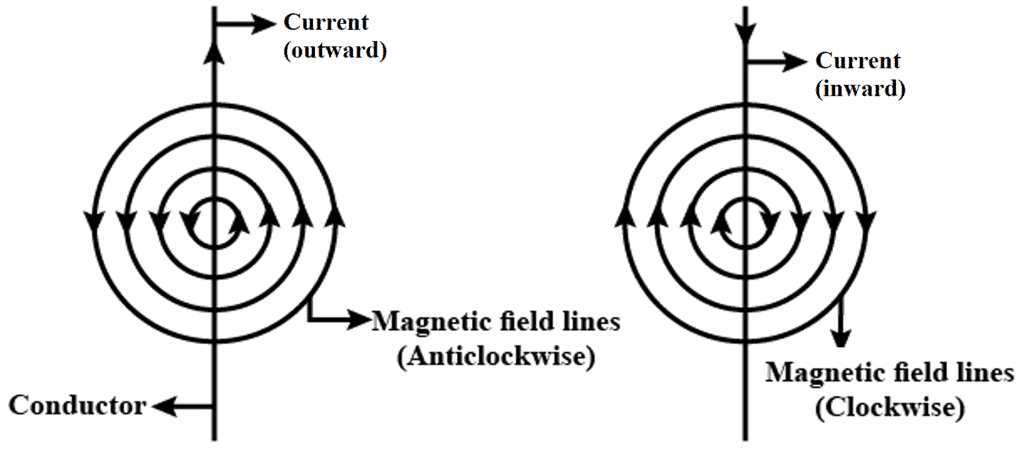
- He found that the alignment of the needle is tangential to an imaginary circle which has the straight wire as its centre and has its plane perpendicular to the wire. Reversing the direction of the current reverses the orientation of the needle.
- The deflection increases on increasing the current or bringing the needle closer to the wire.
- Oersted concluded that moving charges or currents produced a magnetic field in the surrounding space.
Magnetic Field, Magnetic Force, and Lorentz Force
- A magnetic field is like an invisible area around something that's magnetic. It helps us understand how the magnetic force spreads around the object.
- When an electric charge or current moves close to a magnet, it creates a magnetic field. Tiny particles, like electrons with a negative charge, move around and make this magnetic field.
- These fields can start inside the atoms of magnetic things or in wires that have electricity flowing through them.
Magnetic Field is a region of space around a magnet or current-carrying conductor or a moving charge in which its magnetic effect can be felt.
- A magnetic field depicts how a moving charge flows around a magnetic object. Magnetic force is a force that arises due to the interaction of magnetic fields. It can be either a repulsive or attractive force.
- Let us suppose that there is a point charge q (moving with a velocity v and, located at r at a given time t) in the presence of both the electric field E (r) and constant magnetic field B (r).
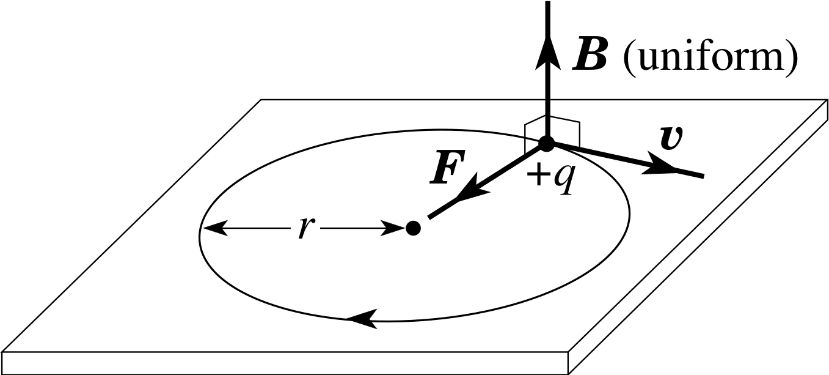
- The force on an electric charge q due to both of them can be written as:
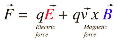
- This force was given first by H.A. Lorentz based on the extensive experiments of Ampere and others. It is called the Lorentz force.
3. Field due to a Straight Current Carrying Wire
3.1 When the wire is of Finite Length
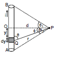
Consider a straight wire segment carrying a current i and there is a point P at which magnetic field to be calculated as shown in the figure. This wire segment makes angle θ1 and θ2 at that point with normal OP. Consider an element of length dy at a distance y from O and distance of this element from point P is r and line joining P to Q makes an angle q with the direction of current as shown in figure. Using Biot-Savart Law magnetic field at point P due to small current element is given by
As every element of the wire contributes to in the same direction, we have
....(i)
From the triangle OPQ as shown in diagram, we have
y = d tan 
or dy = d sec2 d
d
and is same triangle,
r = d sec  and q = (90º -
  ), where
  is angle between line OP and PQ
Now equation (i) can be written in this form
or ...(3)
Note : θ1 & θ2 must be taken with sign
For the case shown in figure
B at A =
Direction of  : The direction of magnetic field is determined by the cross product of the vector
 with
. Therefore, at point P, the direction of the magnetic field due to the whole conductor will be perpendicular to the plane of paper and going into the plane.
Right-hand Thumb Rule : The direction of B at a point P due to a long, straight wire can be found by the right-hand thumb rule. The direction of magnetic field is perpendicular to the plane containing wire and perpendicular from the point. The orientation of magnetic field is given by the direction of curl fingers if we stretch thumb along the wire in the direction of current. Refer figure.
Conventionally, the direction of the field perpendicular to the plane of the paper is represented by if into the page and by
if out of the page.
Now consider some special cases involving the application of equation (3)
Case 1 : When the point P is on the perpendicular bisector
In this case angle θ1 = θ2, using result of equation (3), the magnetic field is
where 
Case - 2
(i) If the wire is infinitely long then the magnetic field at `P' (as shown in the figure) is given by (using q1 = q2 = 90° and the formula `B' due to straight wire)
B = ⇒ B µ

The direction of at various is as shown in the figure. The magnetic lines of force will be concentric circles around the wire (as shown earlier)
(ii) If the wire is infinitely long but `P' is as shown in the figure. The direction of at various points is as shown in the figure. At `P'
B =
Case III : When the point lies along the length of wire (but not on it)
If the point P is along the length of the wire (but not one it), then as and
will either be parallel or antiparallel, i.e., q = 0 or p, so
and hence using equation (1)
Ex-1 Calculate the magnetic field induction at a point distance, metre from a straight wire of length `a' metre carrying a current of i amp. The point is on the perpendicular bisector of the wire.
Sol. B = [sinq1 + sinq2]
= 10-7
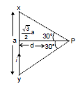
=
Perpendicular to the plane of figure (inward).
Ex.2 Find resultant magnetic field at `C' in the figure shown.

Sol. It is clear that `B' at `C' due all the wires is directed Ä. Also B at `C due PQ and SR is same. Also due to QR and PS is same
Therefore, Bres = 2(BPQ + BSP)
BPQ = (sin 60° + sin 60°)
BSP = (sin 30° + sin 30°)
⇒ Bres = =
Ex.3 Figure shows a square loop made from a uniform wire. Find the magnetic field at the centre of the square if a battery is connected between the points A and C.
Sol. The current will be equally divided at A. The fields at the centre due to the currents in the wires AB and DC will be equal in magnitude and opposite in direction. The resultant of these two fields will be zero. Similarly, the resultant of the fields due to the wires AD and BC will be zero. Hence, the net field at the centre will be zero.
Ex.4 In the figure shown there are two parallel long wires (placed in the plane of paper) are carrying currents 2 I and I consider points A, C, D on the line perpendicular to both the wires and also in the plane of the paper. The distances are mentioned.

Find (i) at A, C, D
(ii) position of point on line A C D where is zero.
Sol. (i) Let us call due to (1) and (2) as
and
respectively. Then
at A : is
and
is
B1 = and B2 =
Therefore, Bres = B1 - B2 =
Ans.
at C: is
and
also
Therefore, Bres = B1 + B2 =
+
=
=
Ans.
 Therefore, Bres = 0 Ans.
(ii) It is clear from the above solution that B = 0 at point `D'.
Biot-Savart's Law
Biot-Savart’s law is an equation that gives the magnetic field produced due to a current-carrying segment. This segment is taken as a vector quantity known as the current element.
- The magnetic field dB due to this element is to be determined at a point P which is at a distance r from it. Let θ be the angle between dl and the displacement vector r.
- According to Biot-Savart’s law, the magnitude of the magnetic field dB is proportional to the current I, the element length |dl|, and inversely proportional to the square of the distance r. Its direction* is perpendicular to the plane containing dl and r.
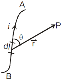 Magnetic filed due to a current element
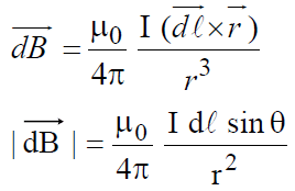
 where
where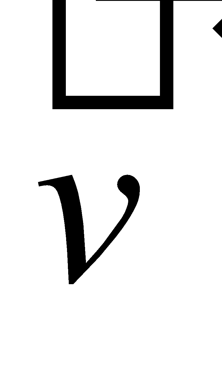 is the drift velocity of the charge.
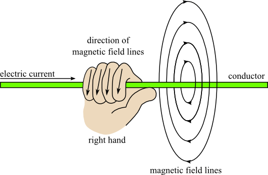 Right-hand thumb rule
Applications of Biot-Savart Law
Magnetic Field at an Axial Point of a Circular Point
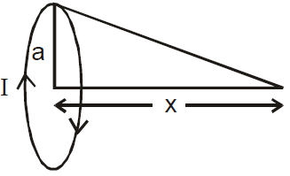
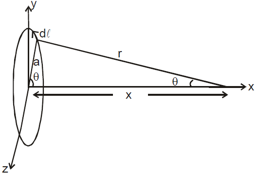
Consider a circular loop of radius R and carrying a steady current i. We have to find out the magnetic field at the axial point P, which is at a distance x from the center of the loop.
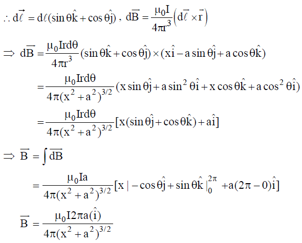
Consider an element i of the loop as shown in the figure, and the distance of point P from the current element is r. The magnetic field at P due to this current element from the equation (1) can be given by,
In the case of a point on the axis of a circular coil, as for every current element, there is a symmetrically situated opposite element, the components of the field perpendicular to the axis cancel each other while along the axis add up.
Therefore, =
Here, q is the angle between the current element id and, which is everywhere and
sin  =
= =
Therefore, B =
or, B =
or, B =
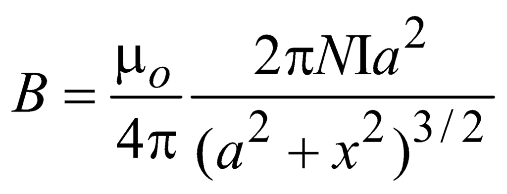
If the coil has N turns, then
B =
Direction of  : The direction of the magnetic field at a point the axis of a circular coil is along the axis and its orientation can be obtained by using the right-hand thumb rule. If the figures are curled along the current, the stretched thumb will point toward the magnetic field.
The magnetic field will be out of the page for anticlockwise current while into the page for clockwise current as shown in the figure given. Now consider some special cases involving the application of equation above.
Case I: Field at the center of the coil
In this case distance of the point P from the center (x) = 0, the magnetic field
B = =

Case II: Field at a point far away from the center
It means x >> R, B =
Example 1: Two-wire loop PQRSP formed by joining two semicircular wires of radii R1 and R2 carries a current i as shown in the figure given below. What is the magnetic field induction at the center O in cases (A) and (B)?
Solution: (a) As point O is along the length of the straight wires, the field at O due to them will be zero and hence the magnetic field is only due to semicircular portions
Therefore,
or, =
out of the page
(b) =
into the page
Example 2: A battery is connected between two points A and B on the circumference of a uniform conducting ring of radius r and resistance R as shown in the figure given below. One of the arcs AB of the ring subtends an angle q at the center. What is the value of the magnetic field at the center due to the current in the ring?
Sol. (a) As the field due to the arc at the center is given by
B =
Therefore, B =
But (VA - VB) = i1R1 = i2R2
or, i2 = i1 = i1
[Therefore, R µ L]
i2 = i1 [Therefore, L = rq]
Therefore, BR =
i.e., the field at the center of the coil is zero and is independent of θ.
Example 3: A charge of one coulomb is placed at one end of a nonconducting rod of length 0.6m. The rod is rotated in a vertical plane about a horizontal axis passing through the other end of the rod with an angular frequency 104π rad/s. Find the magnetic field at a point on the axis of rotation at a distance of 0.8 m from the center of the path.
Now half of the charge is removed from one end and placed on the other end. The rod is rotated in a vertical plane about a horizontal axis passing through the mid-point of the rod with the same angular frequency. Calculate the magnetic field at a point on the axis at a distance of 0.4 m from the center of the rod.
Solution: As the revolving charge q is equivalent to a current
i = qf = q × = 1 ×
= 5 × 10³ A
Now B =

Therefore, B = 10-7 × = 1.13 × 10⁻³ T
If half of the charge is placed at the other end and the rod is rotated at the same frequency, the equivalent current.
i' = = qf = i = 5 × 10³ A

In this case, R' = 0.3 m and x' = 0.4 m
Therefore, B' = 10-7 × = 2.3 × 10⁻³T
Magnetic Field due to Circular Current-Carrying Coil
 B = μ0NI a2/2(a2 + x2)3/2
 is given by Right-hand screw rule.

 ,
, 
 .
. 
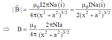
Magnetic Field At The Centre Of A Circular Coil
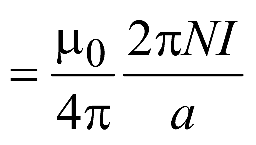
Magnetic Field At The Centre Of A Circular Arc Carrying Current
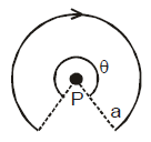

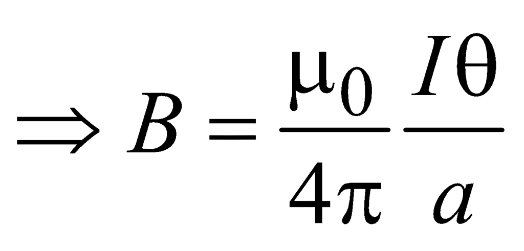
4.1 FIELD AT THE CENTRE OF A CURRENT ARC
Consider an arc of radius R carrying current i and subtending an angle f at the centre.
According to Biot-Savart Law, the magnetic field induction at the point P is given by
B =
Here, dl = Rdθ
Therefore, B = 
or, B = ...(5)
It `l' is the length of the circular arc, we have
B = ...(6)
Consider some special cases involving the application of equation (5)
case I : If the loop is semicircular
In this case  = π, so
B = 
and will be out of the page for anticlockwise current while into the page for clockwise current as shown in the figure.
Case II. If the loop is a full circle with N turns
In this case  = 2p, so
B = 
and will be out of the page for anticlockwise current while into the page for clockwise current as shown in the figure.
Ex.7 Two wire loop PQRSP formed by joining two semicircular wires of radii R1 and R2 carries a current i as shown in the figure given below. What is the magnetic field induction at the centre O in cases (A) and (B) ?
Sol. (a) As the point O is along the length of the straight wires, so the field at O due to them will be zero and hence magnetic field is only due to semicircular portions
Therefore,
or, =
out of the page
(b) =
into the page
Ex.8 A battery is connected between two points A and B on the circumference of a uniform conducting ring of radius r and resistance R as shown in the figure given below. One of the arcs AB of the ring subtends an angle q at the centre. What is the value of the magnetic field at the centre due to the current in the ring?
Sol. (a) As the field due to arc at the centre is given by
B =
Therefore, B =
But (VA - VB) = i1R1 = i2R2
or, i2 = i1 = i1
[Therefore, R µ L]
i2 = i1 [Therefore, L = rq]
Therefore, BR =
i.e., the field at the centre of the coil is zero and is independent of θ.
Ex.9 A charge of one coulomb is placed at one end of a nonconducting rod of length 0.6m. The rod is rotated in a vertical plane about a horizontal axis passing through the other end of the rod with angular frequency 104π rad/s. Find the magnetic field at a point on the axis of rotation at a distance of 0.8 m from the centre of the path.
Now half of the charge is removed from one end and placed on the other end. The rod is rotated in a vertical plane about horizontal axis passing through the mid-point of the rod with the same angular frequency. Calculate the magnetic field at a point on the axis at a distance of 0.4 m from the centre of the rod.
Sol. As the revolving charge q is equivalent to a current
i = qf = q × = 1 ×
= 5 × 10³ A
Now B =

Therefore, B = 10-7 × = 1.13 × 10⁻³ T
If half of the charge is placed at the other end and the rod is rotated at the same frequency, the equivalent current.
i' = = qf = i = 5 × 10³ A

In this case, R' = 0.3 m and x' = 0.4 m
Therefore, B' = 10-7 × = 2.3 × 10⁻³T
Ampere's Circuital Law

- The direction of the magnetic field at a point on one side of a conductor of any shape is equal in magnitude but opposite in direction of the field at an equidistant point on the other side of the conductor.
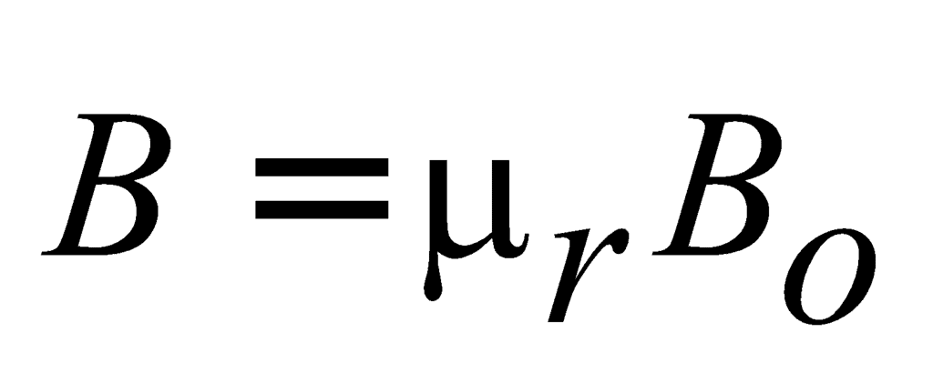
- If the magnetic field at a point due to a conductor of any shape is Bo if it is placed in vacuum then the magnetic field at the same point in a medium of relative permeability μr is given by
 .
. - If the distance between the point and an infinitely long conductor is decreased (or increased) by K-times then the magnetic field at the point increases (or decreases) by K-times.
- The magnetic field at the center of a circular coil of a radius smaller than another similar coil with a greater radius is more than that of the latter.
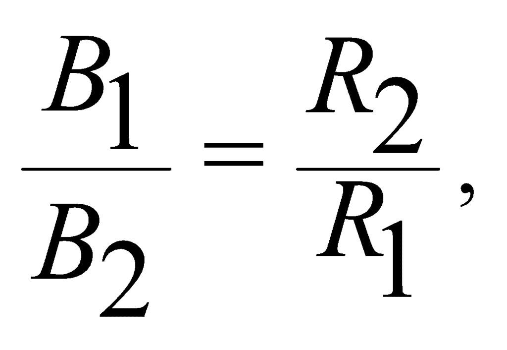
- For two circular coils of radii R1 and R2 have the same current and the same number of turns,
 where B1 and B2 are the magnetic fields at their centers.
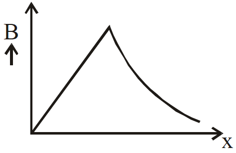
 - The magnetic field at a point outside a thick straight wire carrying current is inversely proportional to the distance but the magnetic field at a point inside the wire is directly proportional to the distance.
Applications of Ampere's Circuital Law
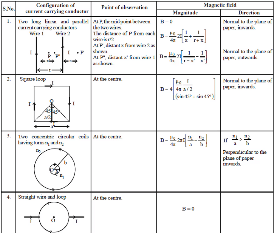
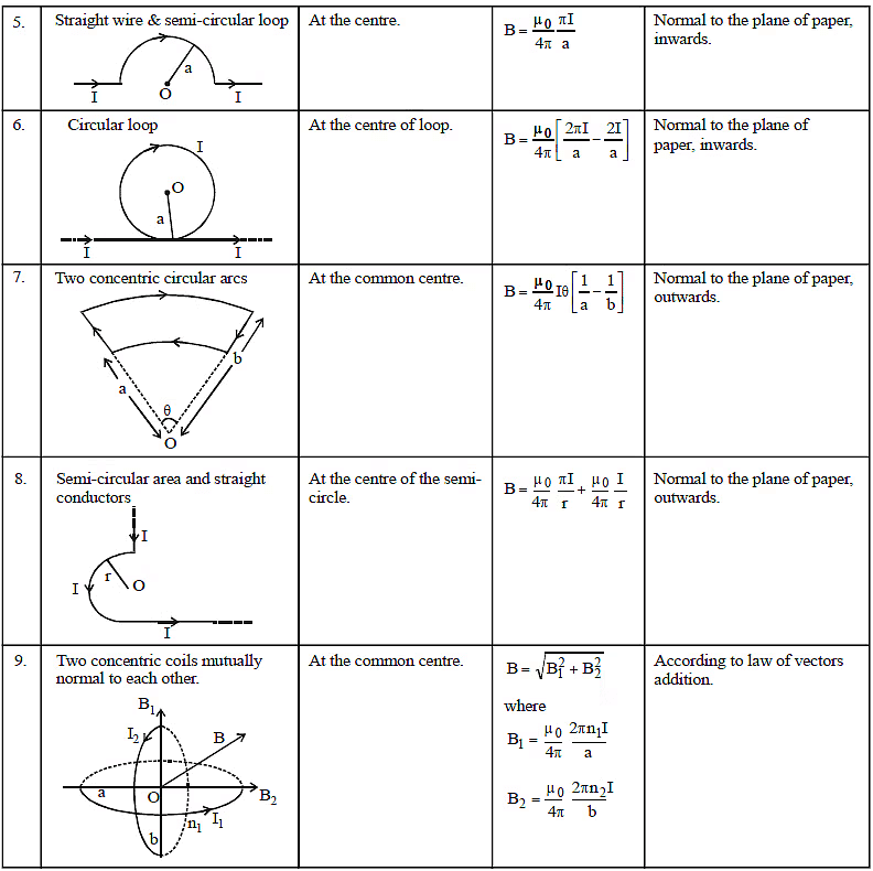
9. Toroid : It is on hollow circular tube have windings of conducting wire closely attached to each other circularly on it (as shown below)
for ideal Toroid d << R
Magnetic field in Toroid
Let N = Total No. of turns
Now from Ampere's circuital law
B.2πR = μ0 iin = μ0 Ni
⇒ B =
n = = No of turns per unit length
so B = μ0 n i
What is Solenoid?
Let us consider a solenoid, such that its length is large as compared to its radius. Here, the wire is wound in the form of the helix with a very little gap between any two turns. Also, the wires are enameled, thus rendering them insulated from each other. As a result, each turn can be taken as a closed circular loop. The magnetic field thus generated is equivalent to that generated by a circular loop and the total magnetic field generated by the solenoid can be given as the vector sum of force generated by each such turn. The magnetic field lines generated inside a finite solenoid has been shown in the figure below.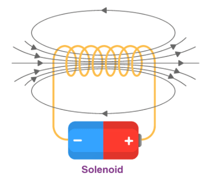
We can see from the figure that the magnetic field inside the solenoid is uniform in nature and is along the axis of the solenoid. The field at the exterior at any point immediately to the solenoid is very weak and the field lines cannot be seen near the close vicinity. It is important to note that the field inside it is parallel to its axis at every position.
From the Ampere’s Law, the magnetic force produced by a solenoid can be given as,
Where n is the number of turns of the wire per unit length, I is the current flowing through the wire and the direction is given using the right-hand thumb rule.
10. Infinite Current Carrying sheet
Now from Ampere's loop
Bl + 0 + Bl + 0 = μ0λ l 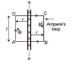
B =
Ex.14 Three identical long solenoids P, Q and R are connected to each other as shown in figure. if the magnetic field at the center of P is 2.0 T, what would be the field at the centre of Q? Assume that the field due to any solenoid is confined within the volume of that solenoid only.
Sol.
As the solenoids are identical, the currents in Q and R will be the same and will be half the current in P. The magnetic field within a solenoid is given by B = μ0 ni. Hence the field in Q will be equal to the field in R and will be half the field in P i.e., will be 1.0 T
11. Magnetic force on moving charge
When a charge q moves with velocity , in a magnetic field
, then the magnetic force experienced by moving charge is given by following formula :
Put q with sign. ...(9)
: Instantaneous velocity
: Magnetic field at that point.
11.1 DIFFERENCE BETWEEN MAGNETIC FORCE AND ELECTRIC FORCE
(1) Magentic force is always perpendicular to the field while electric force is collinear with the field.
(2) Magnetic force is velocity dependent, i.e., acts only when the charged particle is in motion while electric force (qE) is independent of the state of rest or motion of the charged particle.
(3) Magentic force does no work when the charged particle is displaced while the electric force does work in displacing the charged particle.
Note :

Therefore,  Therefore, power due to magnetic force on a charged particle is zero. (use the formula of power P =
  for its proof)
Since the  so work done by magnetic force is zero in every part of the motion. The magnetic force cannot increase or decrease the speed (or kinetic energy) of a charged particle. Its can only change the direction of velocity.
On a stationary charged particle, magnetic force is zero.
If  , then also magnetic force on charged particle is zero. It moves along a straight line if only magnetic field is acting.
Ex.15 A Charged particle of mass 5 mg and charge q = +2μC has velocity . Find out the magnetic force on the charged particle and its acceleration at this instant due to magnetic field
.
and
are in m/s and Wb/m2 respectively.
Sol. = 2 × 10⁻⁶
By Newton's Law
=
Ex.16 A charged particle has acceleration in a magnetic field
. Find the value of x.
Sol.
Therefore, 
Therefore, 
Therefore, = 0
⇒ - 6 + 2x = 0 ⇒ x = 3.
12. Motion of a Charged Particle in a Uniform Magnetic Field
12.1 When the Charged Particle is given velocity perpendicular to the field
Let a particle of charged q and mass m is moving with a velocity v and enters at right angles to a uniform magnetic field as shown in figure.
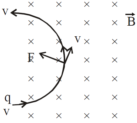
The force on the particle is qvB and this force will always act in a direction perpendicular to v. Hence, the particle will move on a circular path. If the radius of the path is r then
or, r =
...(10)
Thus, radius of the path is proportional to the momentum mv of the particle and inversely proportional to the magnitude of magnetic field.
Time period : The time period is the time taken by the charged particle to complete one rotation of the circular path which is given by,
T = =
...(11)
The time period is independent of the speed v.
Frequency : The frequency is number of revolution of charged particle in one second, which is given by,
 ..(12)
and angular frequency = 
Ex 17. A proton (p), a - particle and deuteron (D) are moving in circular paths with same kinetic energies in the same magnetic field. Find the ratio of their radii and time periods. (Neglect interaction between particles).
Sol. R =
Therefore, Rp : Ra : RD =
= 1 : 1 :
T = 2πm/qB
Therefore, Tp : Ta : TD = :
:
= 1 : 2 : 2 Ans.
Ex.18 A positive charge particle of charge q, mass m enters into a uniform magnetic field with velocity v as shown in the figure. There is no magnetic field to the left of PQ. Find

(i) time spent,
(ii) distance travelled in the magnetic field
(iii) impulse of magnetic force.
Sol. The particle will move in the field as shown. Angle subtended by the arc at the centre = 2q
(i) Time spent by the charge in magnetic field
wt = q ⇒ ⇒ t =
(ii) Distance travelled by the charge in magnetic field :
= r (2θ) = 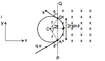
(iii) Impulse = change in momentum of the charge
= (-mv sin θ + mv cos θ ) - (mv sin θ
+ mv cos θ ) = -2mv sinθ
Magnetic Field in a Solenoid
Magnetic Field in Solenoid depends on various factors such as the number of turns per unit length, the current strength in the coil, and the permeability of the material used in the solenoid. The magnetic field of a solenoid is given by the formula:
B = μoIN/L
where,
- μo is the permeability constant with a value of 1.26 × 10⁻⁶ T/m,
- N is the number of turns in the solenoid,
- I is the current passing through the coil,
- L is the coil length.
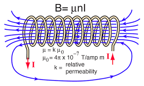
Note: The magnetic field in a solenoid is maximum when the length of the solenoid is greater than the radius of its loops.
Force on a Conductor in Magnetic Field
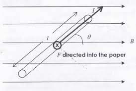 Force on a conductor in Magnetic Field
α is the angle that the conductor makes with the direction of the field.
Magnetic Force between 2 Parallel Currents
Consider the system shown in the figure. Here, we have two parallel current carrying conductor, separated by a distance ‘d’, such that one of the conductors is carrying a current I1 and the other is carrying I2, as shown in the figure. From the knowledge gained before, we can say that the conductor 2 experiences the same magnetic field at every point along its length due to the conductor 1. The direction of magnetic force is indicated in the figure and is found using the right-hand thumb rule. The direction of the magnetic field, as we can see, is downwards due to the first conductor.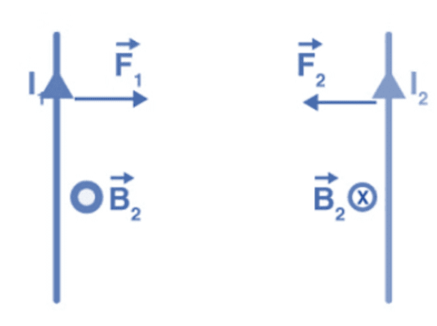 Current Carrying Conductors
From the Ampere’s circuital law, the magnitude of the field due to the first conductor can be given by,
The force on a segment of length L of the conductor 2 due to the conductor 1 can be given as,
Similarly, we can calculate the force exerted by the conductor 2 on the conductor 1. We see that, the conductor 1 experiences the same force due to the conductor 2 but the direction is opposite. Thus,
F12 = F21
We also observe that, the currents flowing in the same direction make the conductors attract each other and that showing in the opposite direction makes the conductors repel each other. The magnitude of force acting per unit length can be given as,

Torque on a coil in Magnetic Field
Force Acting on a Charged Particle in a Uniform Magnetic Field
Consider a positively charged particle that is moving in a uniform magnetic field. Then, the magnitude of the force (magnetic force) is directly proportional to the magnitude of the charge, the component of the velocity that is acting perpendicular to the direction of this field, and the magnitude of the generated magnetic field.
 Force acting on a charged particle

Here, q is the magnitude of the charge, vsinθ is the component of the velocity that is acting perpendicular to the direction of the magnetic field and the B is the magnitude of the applied magnetic field.
F=kqvB sinθ
Here, k is the proportionality constant, whose value is equal to the 1 (k=1). Thus,
F=qvB sinθ
In vector form,
F=qv × B
This is the required expression for the force acting on a moving charge in a uniform magnetic field. There are two cases, for the magnetic force value:
1. Velocity and magnetic field are parallel – In this equation, if the velocity and magnetic field are parallel, then the angle made between the velocity and the magnetic field is zero. This representation of the magnetic force acting on a moving charge in a uniform magnetic field can be expressed as follows.
F=qvB sin θ
2. Velocity or the speed and magnetic field are normal – In case the speed of a particle which is charged becomes normal to the magnetic field. Then, the angle made between them will be equal to 90°. Thus,
F=qvB sin(90)
F=qvB(1)
Fmax=qvB
Maximum force is acting on a moving charge in a uniform magnetic field in this case.
F=qvB(0)
F=0
There is no force in this case.
Torque On Current Loop
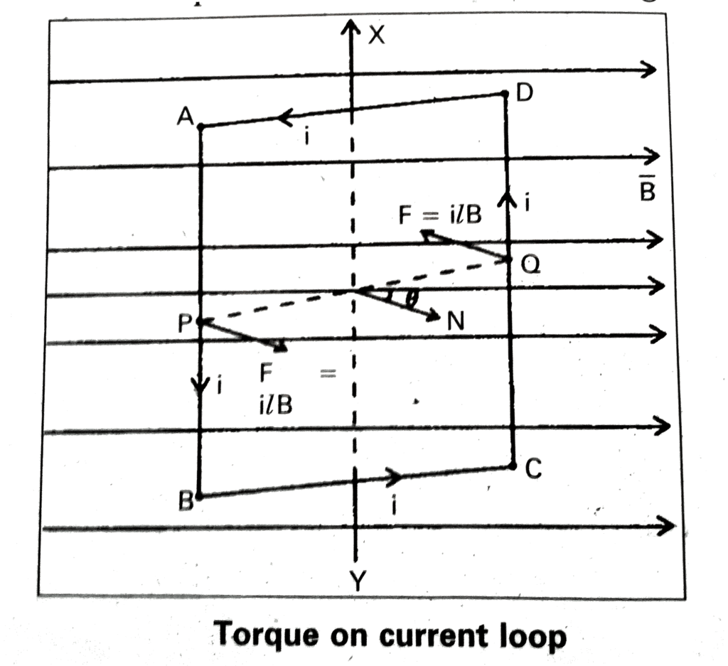
Let us consider a rectangular loop such that it carries a current of magnitude I. If we place this loop in a magnetic field, it experiences a torque but no net force, quite similar to what an electric dipole experiences in a uniform electric field.
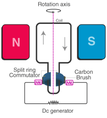 Let us now consider the case when the magnetic field B is in the plane with the rectangular loop. No force is exerted by the field on the arms of the loop that is parallel to the magnets, but the arms perpendicular to the magnets experience a force given by F1,
F1 = lbB
This force is directed into the plane.
Similarly, we can write the expression for a force F2 which is exerted on the arm CD,
F2 = lbB = F1
We see that the net force on the loop is zero and the torque on the loop is given by,

Where ab is the area of the rectangle. Here, the torque tends to rotate the loop in the anti-clockwise direction.
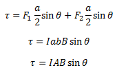
Let us consider the case when the plane of the loop is not along the magnetic field. Let the angle between the field and the normal to the coil be given by θ. We can see that the forces on the arms BC and DA will always act opposite to each other and will be equal in magnitude. Since these forces are the equal opposite and collinear at all points, they cancel out each other’s effect and this results in zero-force or torque. The forces on the arms AB and CD are given by F1 and F2. These forces are equal in magnitude and opposite in direction and can be given by,
F1 = F2 = lbB
These forces are not collinear and thus act as a couple exerting a torque on the coil. The magnitude of the torque can be given by,
Torque On Current Loop – The Magnetic moment
The magnetic moment of a current loop can be defined as the product of the current flowing in the loop and the area of the rectangular loop. Mathematically,
m = IA
Here, A is a vector quantity with the magnitude equal to the area of the rectangular loop and the direction is given by the right-hand thumb rule. In the equation written earlier, we can see that the torque exerted on a current-carrying coil placed in a magnetic field can be given by the vector product of the magnetic moment and the magnetic field.
τ = mxB
Moving Coil Galvanometer
 Moving Coil Galvanometer
- It essentially consists of a rectangular coil PQRS or a cylindrical coil of a large number of turns of fine insulated wire wound over a non-conducting frame of ivory or bamboo.
- This coil is suspended by means of phosphor bronze wire between the pole pieces of a powerful horseshoe magnet NS. The poles of the magnet are curved to make the field radial. The lower end of the coil is attached to a spring of phosphor-bronze wire.
- The spring and the free ends of the phosphor bronze wire are joined to two terminals T2 and T1 respectively on the top of the case of the instrument. L is a soft iron core. A small mirror M is attached to the suspension wire.
- Using lamp and scale arrangement, the deflection of the coil can be recorded. The whole arrangement is enclosed in a non-metallic case.
- Due to this torque, the coil rotates. As a result, the suspension wire gets twisted. Now a restoring torque is developed in the suspension wire.
- The coil will rotate till the deflecting torque acting on the coil due to the flow of current through it is balanced by the restoring torque developed in the suspension wire due to twisting.
- Let C be the restoring couple for a unit twist in the suspension wire and θ be the angle through which the coil has turned. The couple for this twist θ is Cθ.In equilibrium, deflecting couple = restoring couple∴ ni AB = Cθ or i = Cθ/ (nAB)or i = Kθ (where C/nAB = K) … (2)K is a constant for a galvanometer and is known as a galvanometer constant.Hence
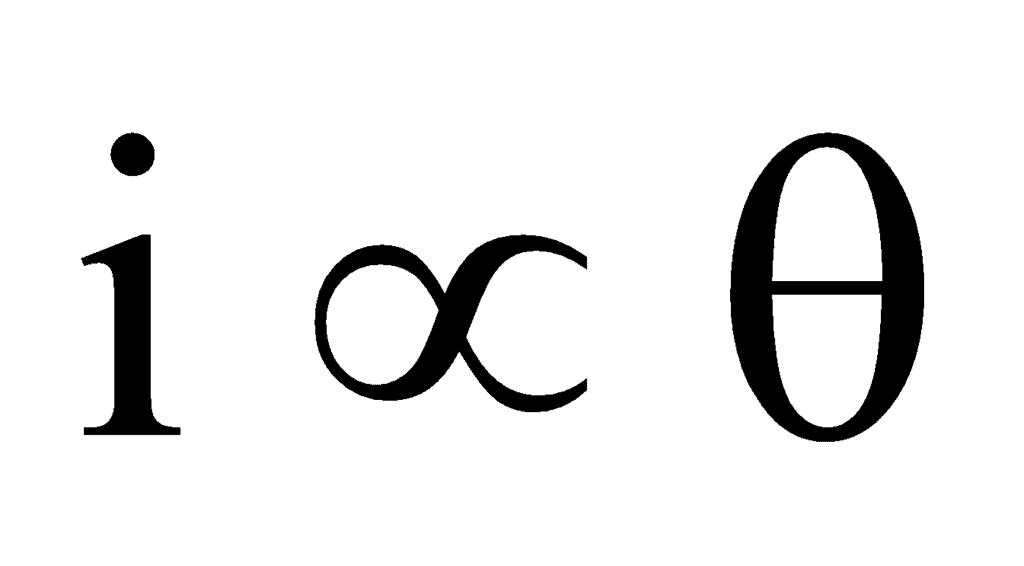 Therefore, the deflection produced in the galvanometer is directly proportional to the current flowing through it.Current sensitivity of the galvanometer: The current sensitivity of a galvanometer is defined as the deflection produced in the galvanometer when a unit current is passed through it.We know that, niAB = Cθ∴ Current sensitivity is =where C = restoring couple per unit twistThe SI unit of current sensitivity is radian per ampere or deflection per ampere.Voltage sensitivity of the galvanometer : The voltage sensitivity of the galvanometer is defined as the deflection produced in the galvanometer when a unit voltage is applied across the terminals of the galvanometer.∴ Voltage sensitivity
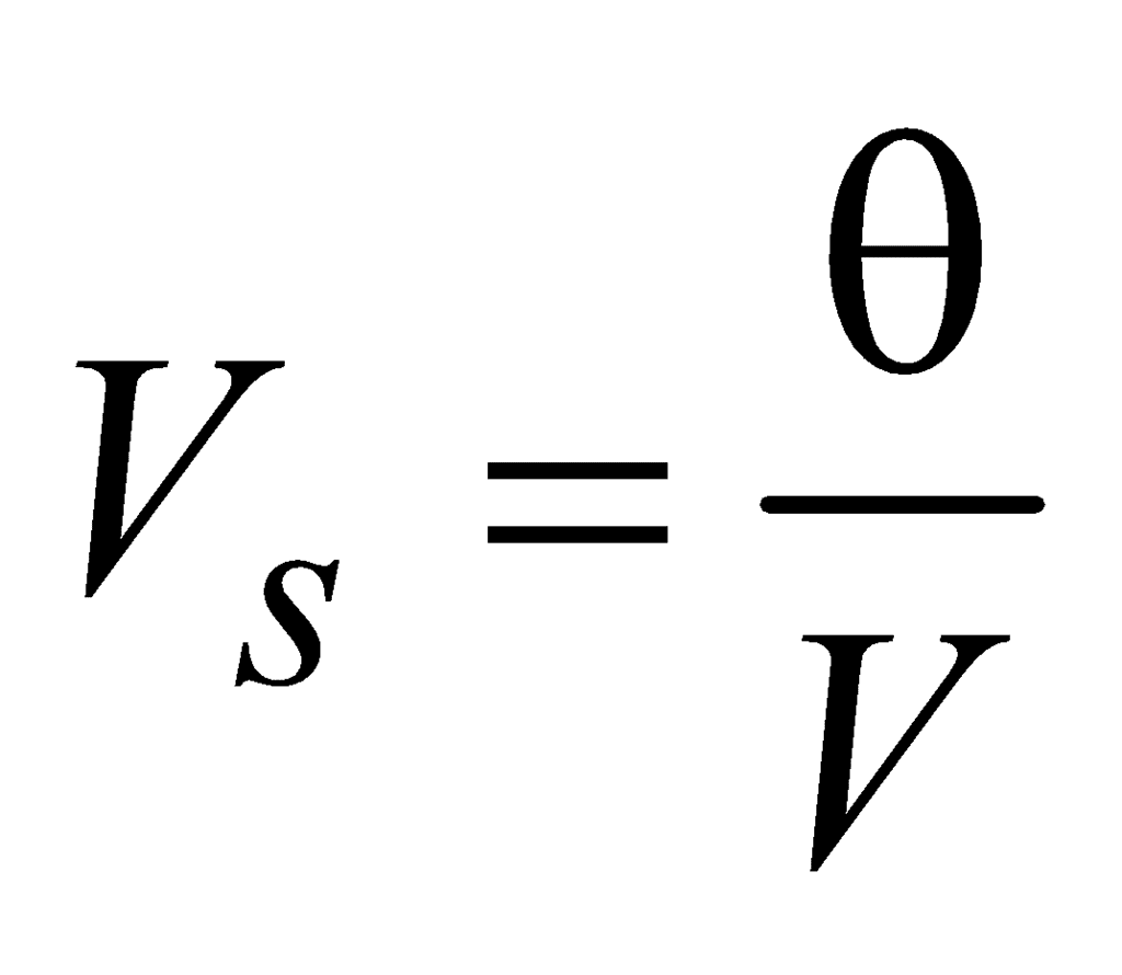 , If R is the resistance of the galvanometer and a current is passed through it, then V = iR∴ Voltage sensitivity, Vs =
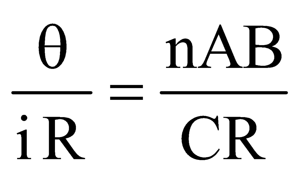 The SI unit of voltage sensitivity is radian per ampere or deflection per ampere.Conditions for sensitivity: A galvanometer is said to be more sensitive if it shows a large deflection even for a small value of current.We know that,For a given value of i, θ will be large if (i) n is large, (ii) A is large, (iii) B is large, and (iv) C is small.Regarding the above factors, n, and A cannot be increased beyond a certain limit. By increasing n, the resistance of the galvanometer will increase and by increasing A, the size of the galvanometer will increase. So, the sensitivity will decrease. Therefore, B is increased. The value of B can be increased by using a strong horseshoe magnet. Further, the value of C can be decreased. The value of C for quartz and phosphor-bronze is very small. So, the suspension wire of quartz or phosphor-bronze is used. The value of C is further decreased if the wire is hammered into a flat strip.
Summary
- If in a coil the current is clockwise, it acts as a south pole. If the current is anticlockwise, it acts as a north pole.
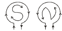
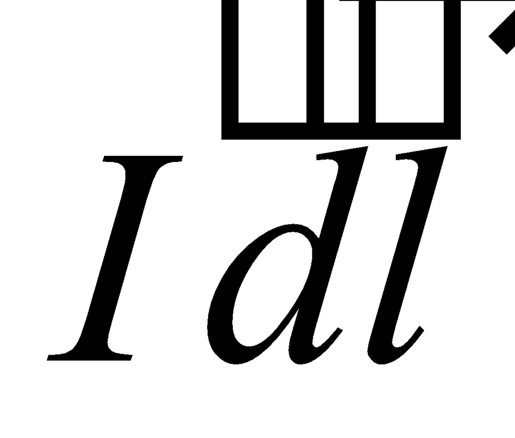
- No magnetic field occurs at points P, Q, and R due to a thin current element
 .
.
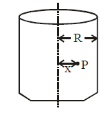
- Magnetic field intensity in a thick current-carrying conductor at any point x is:


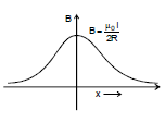
- Graph of magnetic field B versus x:

- If the charges move, the electric as well as magnetic fields are produced. In case the charges move with speeds comparable to the speed of light, magnetic and electric force between them would become comparable.
- A current-carrying coil is in stable equilibrium if the magnetic dipole moment
 is parallel to
  and is in unstable equilibrium when
  is antiparallel to
  .
. - The magnetic moment is independent of the shape of the loop. It depends on the area of the loop.
- A straight conductor and a conductor of any shape in the same plane and between the same two endpoints carrying equal current in the same direction, when placed in the same magnetic field experience the same force.
- There is net repulsion between two similar charges moving parallel to each other in spite of attractive magnetic force between them. This is because of the electric force of repulsion which is much stronger than the magnetic force.
- The speed of the charged particle can only be changed by an electric force.
- The force on a conductor carrying current in a magnetic field is directly proportional to the current, the length of the conductor, and the magnetic field.
- If the distance between the two parallel conductors is decreased (or increased) by k-times then the force between them increases (or decreases) k-times.
- The momentum of the charged particle moving along the direction of the magnetic field does not change, since the force acting on it due to the magnetic field is zero.
- Lorentz force between two charges q1 and q2 moving with velocity v1, v2 separated by distance r is given by
- No force acts on a charged particle if it enters a magnetic field in a direction parallel or antiparallel to the field.
- A finite force acts on a charged particle if it enters a uniform magnetic field in a direction with a finite angle with the field.
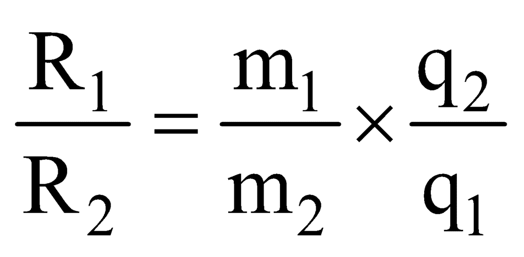
- If two charged particles of masses m1and m2 and charges q1 and q2 are projected in a uniform magnetic field with the same constant velocity in a direction perpendicular to the field then the ratio of their radii (R1: R2) is given by
|
74 videos|314 docs|88 tests
|
FAQs on Moving Charges and Magnetism Chapter Notes - Physics Class 12 - NEET
| 1. What is the Oersted experiment and what did it demonstrate about the relationship between electricity and magnetism? |  |
| 2. How does the Biot-Savart Law help in calculating the magnetic field due to a current-carrying conductor? |  |
| 3. What is Ampere's Circuital Law and how is it applied in magnetic field calculations? |  |
| 4. How does the magnetic field inside a solenoid compare to that outside it? |  |
| 5. What is the significance of the force experienced by a conductor in a magnetic field? |  |


