Dual Converter | Power Electronics - Electrical Engineering (EE) PDF Download
Introduction
Dual converter: The name itself indicates that it has two converters in it. It is an electric device mostly found in variable speed drivers. It is a power electronics control system to get either polarity DC from AC rectification by the forward converter and reverse converter. In a dual converter, two converters are connected together back to back.
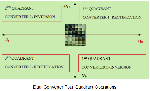
One of the bridge works as a rectifier (converts AC to DC), another half bridge works as an inverter (converts DC to AC) and connected commonly to a DC load. Here two conversion processes take place simultaneously, so it is called as a dual converter. The dual converter can provide four quadrant operations. The four quadrant operation is shown below.
Principle of Dual Converter
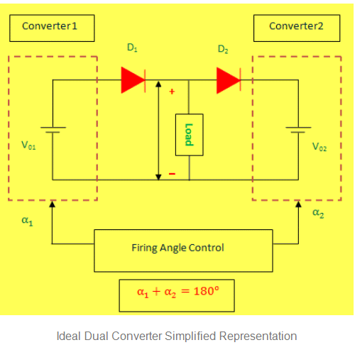
The dual converter basic principle of operation can be explained with reference to the simplified equivalent diagram of the DC circuit shown in the figure below. In this simplified representation, two assumptions are made.
- Dual converters are ideal that means they produce pure DC output terminals without containing any ripples.
- Each two-quadrant converter is assumed to be a controllable direct voltage source, connected in series with a diode.
Here Diode D1 and D2 represent the unidirectional current flow characteristics of the converters. However, the direction of current can be in any way. Let us assume, the average output voltage of the converter 1 is V01 and converter 2 is V02. To make the output voltage of the two converters in same polarity and magnitude, the firing angles of the thyristors have to be controlled.
To know more about thyristor, please follow the link: Thyristor or Silicon Controlled Rectifier Tutorial basics and Characteristics
Average output voltage of Single-phase converter = 2Vm COSα/ π
Average output voltage of Three-phase converter = 3Vm COSα/ π
For converter 1, the average output voltage, V01= Vmax COSα1
For converter 2, the average output voltage, V02= Vmax COSα2
The Output voltage is given by,
The firing angle can never be greater than 180. So, α1+ α2= 1800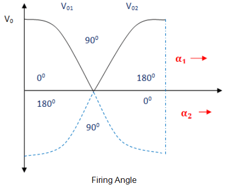
Modes of Operation of Dual Converter
There are two functional modes: Non-circulating current mode and circulating mode.
Non-Circulating Current Mode
- One converter will perform at a time. There is no circulating current between the converters.
- During the converter 1 operation, the firing angle (α1) will be 0<α1< 900 (Vdc and Idc are positive)
- During the converter 2 operation, firing angle (α2) will be 0<α2< 900 (Vdc and Idc are negative)
Circulating Current Mode
- In this mode, both converters will be in the ON condition at the same time. So circulating current is present.
- The firing angles are adjusted such that α1+ α2=180°. Firing angle of converter 1 is α1 and firing angle of converter 2 is α2.
- In this mode, the Converter 1 works as a controlled rectifier when the firing angle is 0<α1< 900 and Converter 2 works as an inverter when the firing angle is 90° <α2< 180°. In this condition, Vdc and Idc are positive.
- Converter 1 works as an inverter when firing angle be 90° <α1< 180°and Converter 2 works as a controlled rectifier when the firing angle is 0<α2< 90° in this condition, Vdc and Idc are negative.
Single Phase Dual Converter
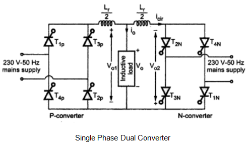
The blow shown figure shows single phase dual converter using thyristors. As explained above, in single phase dual converter we use single phase rectifier circuit for converting single phase AC into steady DC.
The Converter 1 consists of Rectifier. Then the rectified DC fed to a filter which removes pulses from rectified DC and converts it to a pure DC by filtering.
After that, this pure DC is fed to load and from the load, it is given to inverter circuit which converts this DC to AC and finally this AC of inverter taken as the output.
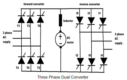
Three Phase Dual Converter
In three phase dual converter, we make use of three phase rectifier which converts 3 phase AC supply to DC. The structure of the converter is same as single phase dual converter.
The output of three phase rectifier is fed to filter and after filtering the pure DC is fed to the load. At last, the supply from the load is given to last bridge that is inverted. It does the Invert process of the rectifier and converts DC into 3 phase AC, which is output.
Applications of Dual Converter
- Direction and Speed control of DC motors.
- Applicable wherever, the reversible DC is required.
- Industrial variable speed DC drives.
Direction and Speed Control of DC Motors using Dual Converter
The dual converter is a power electronics control system to get either polarity DC from AC rectification by the forward converter and reverse converter. It can run a DC motors in either direction with speed control too.
This single phase converter is achieved by using a pair of a thyristor controlled bridge (4 SCRs X 2) that enables the DC motor to get reversed polarity for either direction rotation and speed control also lowered in steps by Microcontroller triggering each bridge SCR bank of duly interfaced through Opto-isolators.
A pair of switches is used to input logical signal for the desired output. If the input of 230 volt AC is given to the dual SCR Bridge we can have a 100-watt lamp load and the DC polarity across the lamp is checked or a low power DC motor of 220 volts can be used.
This project uses 12-volt ac at the input and a 12 volt DC motor to verify either direction rotation as the polarity gets reversed.
|
5 videos|67 docs|46 tests
|


