Electricity Class 10 Notes Science Chapter 11

Electricity plays a crucial role in our modern world, powering everything from homes and schools to hospitals and industries. But what exactly is electricity? How does it travel through an electric circuit? And what factors influence the flow of current? In this chapter, we'll explore these questions, uncover the principles behind electric circuits, and delve into the heating effects of electric current and its many practical applications.
Electricity originated from the Greek words “Electrica” and “Elektron”. The greek philosopher Thales was the first to observe the attracting capacity of certain materials when rubbed together.
Electric Current and Circuit
- Electricity is one of the most convenient and widely used forms of energy in the world.
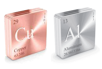
- Conductors are those substances in which electric charge can flow freely. Metals are electric conductors. Copper and aluminium are the two most commonly used metals in electricity.
- Electrical insulators are those materials in which electric charges do not move freely. Rubber, glass and plastic are examples of insulators.
 Electrical Insulators
 - Current electricity is the electricity which deals with moving charges.
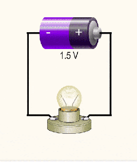
- A continuous and closed path of an electric current is called an electric circuit.
 Electric Circuit
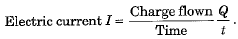
 - Electric current is defined as the rate of flow of electric charge through a cross-section of a conductor.
 The flow of electric current
- S.I. unit of electric current is ‘ampere' (A). One-ampere current is equivalent to the flow of 1 coulomb of charge per second through a section of a conductor. Thus, 1 A = 1 C s-1.
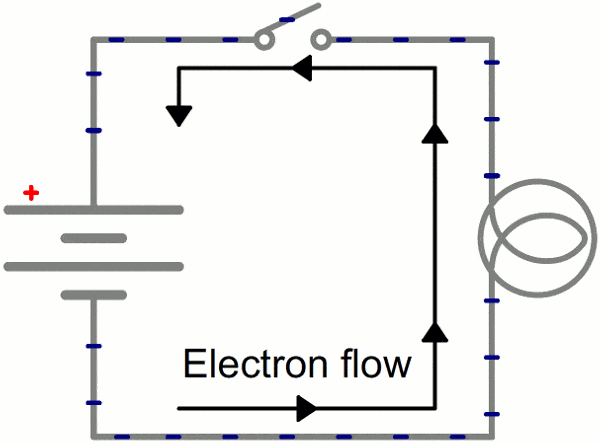
- The direction of the flow of electric current is taken as opposite to the direction of the flow of negatively charged electrons. In other terms, the direction of conventional current is taken as the direction along which positive charges will move if allowed to do so
- In conductors flow of electric current is due to the flow of electrons. The flow of 6.25 x 10¹⁸ electrons per second across a cross-section of a conductor constitutes a current of 1 ampere.
Solved example
A current of 0.75 A flows through a heater for 8 minutes. Calculate the amount of electric charge that passes through the circuit.
Solution:
Given:
Current, I=0.75A
Time,
Using the formula:
Q=It
Q=0.75A×480s
Q=360C
So, the electric charge that flows through the circuit is 360 C.
Electric Potential & Potential Difference
The flow of electric charge in a circuit is similar to water flow in a pipe.
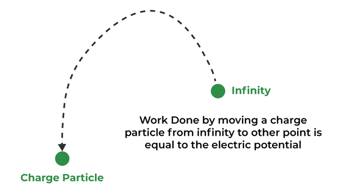
- The water pipe is analogous to the electric conductor and the amount of water flowing across a section per second corresponds to electric current.
- As water flows from higher pressure (level) to lower pressure (level), the electric current flows from higher electric potential to lower electric potential.
- The potential difference across a conductor is maintained by using a cell or battery.
- The chemical action within a cell generates the potential difference between its electrodes, due to which current flows through the circuit.
- Potential difference between two points in an electric circuit carrying current is defined as the work done to move a unit positive charge from one point to another. If
 be the amount of work done in taking a charge Q from point B to point A, then
- The SI unit of electric potential difference is volt (V), where
Solved example
How much work is done in moving a charge of 3 C between two points with a potential difference of 9 V?Solution:
The charge Q flowing between the two points with a potential difference V = 9V is 3 C. The work W done in moving the charge can be calculated using the formula:
C
JSo, 27 J of work is done in moving the charge.
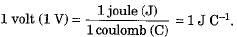
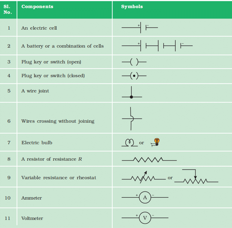
Circuit Diagram
- A circuit diagram is a simplified representation of the components of an electrical circuit using either the images of the distinct parts or standard symbols.
- It shows the relative positions of all the elements and their connections to one another.
- It is often used to provide a visual representation of the circuit to an electrician. The following figure shows a simple circuit diagram.
Components of Circuit Diagram
Ohm's Law
George Simon Ohm established a relationship between the electric current flowing through a conductor and the potential difference across its ends, due to which current flows.
- According to Ohm’s law, the temperature remaining constant, the current passing through a conductor is directly proportional to the potential differenceacross its ends, i.e.,
V ∝ I or V = IR
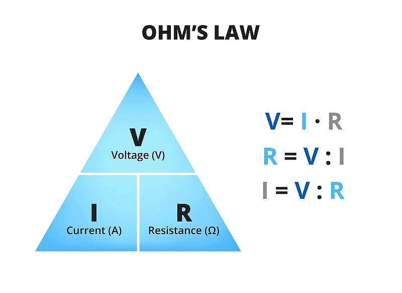
- Here, constant R is known as the resistance of the given conductor. For a given conductor its resistance is constant at a given temperature.
- Electrical resistanceof a conductor may be considered as a measure of the opposition offered by it for the flow of electric charge through it.
Mathematically, Resistance
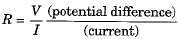
- S.I. unit of electrical resistance is ohm(Ω), where 1 Ω = 1V/1A.
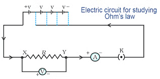
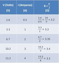
Lets do one activity to understand Ohm's law more clearly
Objective:
To study the relationship between the potential difference (V) across a nichrome wire and the current (I) passing through it by varying the number of cells in a circuit.Materials Needed:
Nichrome wire (length 0.5 m), Ammeter, Voltmeter, Four 1.5 V cells, Connecting wires, Switch, Circuit board
Procedure:
Set Up the Circuit:
- Connect the nichrome wire (XY) to a circuit that includes an ammeter in series, a voltmeter in parallel with the wire, and one 1.5 V cell as the power source.
Measure and Record Readings:
- Close the switch and note the current (I) from the ammeter and the potential difference (V) across the nichrome wire from the voltmeter.
- Record these values in a table.
Increase the Number of Cells:
- Add another cell to the circuit to increase the voltage. Again, note the values of current (I) and potential difference (V) and record them.
- Repeat this step by adding a third and then a fourth cell to the circuit, each time noting the ammeter and voltmeter readings.
Tabulate the Results:
Create a table with the number of cells, corresponding potential difference (V), and current (I) readings.
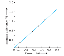
In this Activity, you will find that approximately the same value for V/I is obtained in each case. Thus the V–I graph is a straight line that passes through the origin of the graph,Thus, V/I is a constant ratio. R is a constant for the given metallic wire at a given temperature and is called its resistance. It is the property of a conductor to resist the flow of charges through it.
Important note:-
It is obvious from the ohm's law equation that the current through a resistor is inversely proportional to its resistance. If the resistance is doubled the current gets halved.
Factors Affecting Resistance of a Conductor
- At a given temperature resistance of a conductor depends on its:
(i) Length L
(ii) Cross-section area A
(iii) Nature of the material of the conductor.
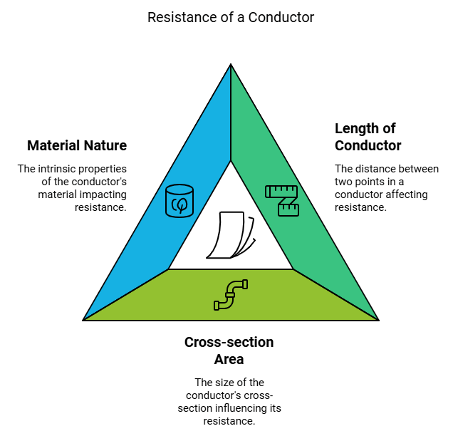
- It is found that R ∝ L and

Mathematically, R = ρL/A
- Where ρ is a constant known as the resistivity of the material of the conductor, its value depends only on the nature of the material of the conductor and the temperature and is independent of the dimensions (i.e., length and cross-section area) of the conductor.
- The resistivity of a given material is defined as the resistance offered by a cube of that material of side 1 m when current flows perpendicular to the opposite faces. Its unit is ohm-metre (Ω m).
- Metals and alloys have low resistivity in the range of 10-8 Ω m to 10-6 Ω m and are good conductors of electricity.
- Insulators like rubber and glass have a resistivity of the order of 1012 to 1017 Ω m.
- Resistance, as well as the resistivity of a material, varies with temperature. For metallic conductors resistance as well as resistivity increases with an increase in temperature.
- Resistivity of pure metals is very very low. On account of this reason, metals like copper and aluminium are used for electrical transmission lines.
- Resistivity of alloys is greater than that of pure metals. However, alloys do not oxidise easily, and their change in resistivity with the temperature rise is small. Due to these properties, they are used as electrical elements in most electric appliances. Generally, nichrome elements are used in electric iron, heater, radiator, geyser etc.
- Tungsten filaments are used in electric lamps because the melting point of tungsten is extremely high.
- A rheostat is a variable resistance device used in electrical circuits. It is used to regulate the current in the circuit without changing the voltage source.
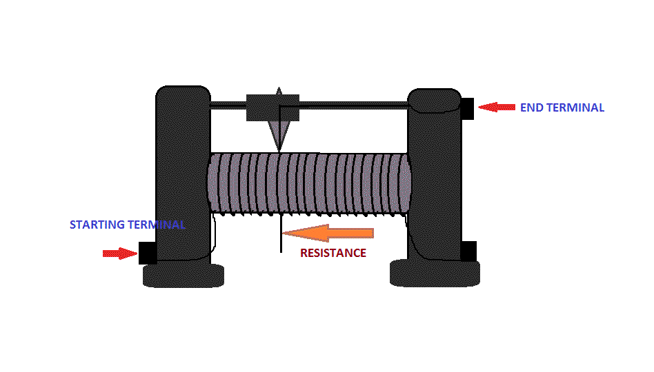 A Rheostat
 - An ammeter is an instrument that can measure the electric current flowing in an electric circuit directly in amperes and their submultiples.
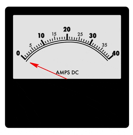 Ammeter
- A voltmeter is an instrument used to measure the potential difference across two given points in an electrical circuit directly in volts.
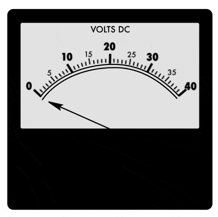 Voltmeter
Solved example
The resistance of a metal wire of length 1.5 m is 30 Ω at 25°C. If the diameter of the wire is 0.4 mm, what will be the resistivity of the metal at that temperature?Solution:
Given:
Resistance
Diameter 4×10⁻⁴m
Length 1.5m
To find the resistivity ρ of the metal, use the formula:
ρ=RA/l= Rπd2/4lSubstituting the given values:
2.51×10⁻⁶ΩmThe resistivity of the metal at 25°C is2.51×10−6Ωm.
Another Solved example
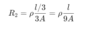
A wire made of a specific material has a length l and a cross-sectional area A, with a resistance of 6 Ω. What would be the resistance of another wire made of the same material but with a length of l/3 and a cross-sectional area of 3A?
Solution:
For first wire
For second wire
R2 = 1/9 ρl/A
R2= 1/9 R1
R2= 1ΩThe resistance of the new wire is 1Ω.
Resistance of System of Resistors
In an electric circuit resistances may be connected in:
(i) Series
(ii) Parallel Arrangement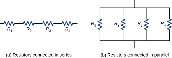
In the series grouping of resistances:
(i) The current flowing through all the resistances is the same.
(ii) The total voltage across the combination is equal to the sum of the voltage drops across the individual resistors.
(iii) The total resistance of the combination is equal to the sum of the individual resistances.
(iv)If R1, R2, R3,... be the individual resistors joined in series then the equivalent resistor Rs is given by Rs = R1 + R2 + R3 + ...
In the parallel grouping of resistances:
(i) The voltage across each resistor is the same and equal to the voltage across the whole combination.
(ii) The currents in various resistors are inversely proportional to the resistances, and the total current is the sum of the currents flowing through different resistances, and (Hi) the sum of the reciprocals of the separate resistances is equal to the reciprocal of equivalent resistance. If R1, R2, R3,... be the individual resistors joined in parallel then the equivalent resistance Rp is given as :
In household electric circuits, a series circuit is not followed. It is because if one component of the series circuit fails, the entire circuit is broken and none of the components works. Moreover, the same current flows through all the components irrespective of their operating needs.
- A parallel circuit divides the current into various components (appliances), and each component can draw current as per its appropriate operation. Separate on/off switches can be put with each component in the parallel circuit. Moreover, the total resistance in parallel circuit arrangement decreases and hence a stronger current can be drawn from a voltage source. Due to these reasons, all appliances are connected in parallel in our household electric circuit.
Solved example
An electric lamp of resistance 20Ω and a conductor of resistance 4Ω are connected to a 6V battery as shown in the circuit. Calculate:(a) The total resistance of the circuit
(b) The current through the circuit
(c)The potential difference across the (i) Electric lamp and (ii) Conductor, and
(d) Power of the lamp.
Solution:
Given, Resistance of electric lamp, R 1 = 20 ohm
Resistance of conductor, R 2 = 4 ohm
Potential difference, V = 6 V
(a) Since R 1 and R 2 are connected in series,Total resistance, R = R 1 + R 2
= 20 + 4
= 24 ohm
Therefore, total resistance of the circuit is 24 ohm.
(b) Let the current through the circuit be I.
According to ohm’s law,
V = I x R
I = V / R
= 6 / 24
= 0.25 A
Therefore, the current through the circuit is 0.25 A
(c) (i) For electric lamp,
V = I x R 1
= 0.25 x 20
= 5 V
Therefore, the potential difference across the electric lamp is 5 V.
(ii) For conductor,
V = I x R 2
= 0.25 x 4
= 1 V
Therefore, the potential difference across the conductor is 1 V.
(d)Let the power of the lamp be P.
We know that,
P = V x I
= 5 x 0.25
= 1.25 W
Therefore, power of the lamp is 1 . 25 W
Heating Effect of Electric Current
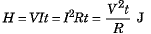
- If on applying, a potential difference V across the ends of a conductor of resistance R, the current I flows for a time t, then as per Joule’s law of heating the electric energy consumed is given by:
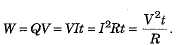
- Generally, it is convenient to use the formula W = I2Rt for series-connected circuits because the current I is the same in all resistors. For parallel arrangement, we prefer to use the relation
 because here V is the same across all branches of the circuit.
 - The dissipated electrical energy reappears as heat. Thus, the heat produced:
Solved exampleAn electric heater uses 900 W of power when operating at maximum heat and 400 W at minimum heat. The voltage across it is 240 V. What are the current and resistance of the heater in each case?
Solution:
Using the formula the current can be calculated as:
(a) Maximum Heating:
900W
240V
The resistance R is:
(b) Minimum Heating:
V
The resistance is:So, at maximum heating, the current is 3.75 A and the resistance is 64 Ω. At minimum heating, the current is 1.67 A and the resistance is 143.71 Ω.
Practical Applications of Heating Effect of Electric Current
1. Electric heating is also used to produce light in electric bulbs. As bulb filament operates at very high temperatures, the filament should be thermally insulated. The bulb is filled with chemically inactive nitrogen and argon gases to prolong the life of the bulb filament.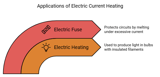
2. Electric fuse protects an electric circuit or appliance by stopping the flow of any unduly high electric current.
- A fuse consists of a piece of wire of a metal or an alloy of an appropriate melting point and is placed in series with the circuit.
- If a current larger than the specified value flows through the circuit, the temperature of the fuse wire rises beyond its melting point, and the fuse melts. As a result, the circuit breaks.
 Electric Fuse
 - The fuse of appropriate current capacity is used in an electric circuit.
Electric Power
The time rate of doing electric work is called electric power. Thus,
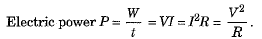
- SI unit of electric power is watt (W), where 1 watt = 1 volt x 1 ampere = 1 V A
- A watt-hour and kilowatt-hour are practical units of electric energy. The commercial unit of electric energy is a kilowatt-hour (kW h), where
1 kW h = 1000 Wh = 3.6 x 10⁶ J.
|
80 videos|569 docs|80 tests
|
FAQs on Electricity Class 10 Notes Science Chapter 11
| 1. What is electric current and how is it measured? |  |
| 2. What is the difference between electric potential and potential difference? | |
| 3. How does Ohm's Law relate voltage, current, and resistance? | |
| 4. What are the factors that affect the resistance of a conductor? | |
| 5. How is the total resistance calculated in a series and parallel circuit? | |


Previous Year Questions with Solutions
,Semester Notes
,Extra Questions
,mock tests for examination
,Electricity Class 10 Notes Science Chapter 11
,Exam
,Objective type Questions
,video lectures
,ppt
,MCQs
,shortcuts and tricks
,Important questions
,past year papers
,Electricity Class 10 Notes Science Chapter 11
,Sample Paper
,practice quizzes
,study material
,Viva Questions
,Electricity Class 10 Notes Science Chapter 11
,Free
,Summary
;


Chapter Notes: Electricity Free PDF Download
Importance of Chapter Notes: Electricity
Chapter Notes: Electricity
Chapter Notes: Electricity Class 10 Questions
Study Chapter Notes: Electricity on the App
|
© EduRev
|
Education Revolution
|


|


within 7 days!