Force on a Current Carrying Conductor & Fleming's Left & Right Hand Rule | Science Class 10 PDF Download

Force on a Current Carrying Conductor Placed in a Magnetic Field
A conductor that carries current generates a magnetic field around itself. When this conductor is placed within an external magnetic field, the two magnetic fields interact, resulting in a net force acting on the conductor.
If a conductor of length l, carrying current I, is positioned in a magnetic field with intensity B and forms an angle θ with it, the force on the conductor can be calculated using:
F = IlB sin Θ
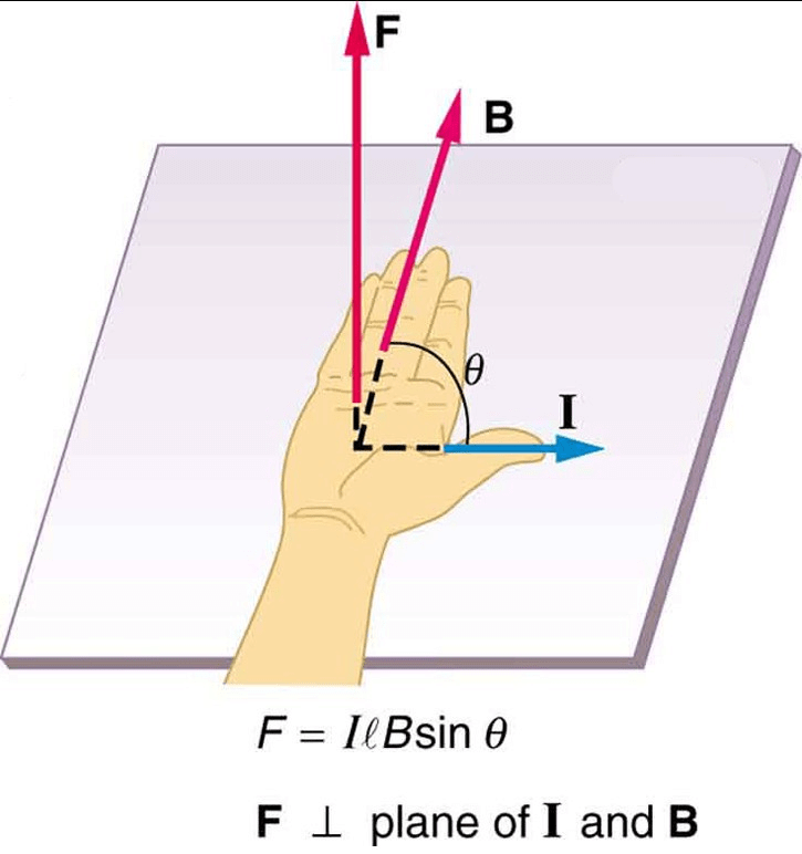 If the conductor is lying perpendicular to the magnetic field, then
θ = 90° [sin θ = 1] and the force becomes F = IlB.
This force acts in a direction that is perpendicular to the plane formed by the conductor and the magnetic field, reaching its maximum value. The displacement of the rod is greatest when the current flows at right angles to the magnetic field direction.
If the conductor runs parallel to the magnetic field, then θ = 0° (where sin θ = 0), making the force zero, which is its minimum.
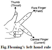
Fleming's Left Hand Rule
The direction of the force on a current-carrying conductor in a magnetic field is described by Fleming's Left Hand Rule. This rule states that:
If you stretch your left hand so that your forefinger, second finger, and thumb are at right angles to each other, with the forefinger pointing in the direction of the magnetic field and the second finger pointing in the direction of the current, the thumb shows the direction of the force. Remember, if the direction of the current changes, the direction of the force will also change.
Factors on which the force acting on the current carrying conductor depends
The force acting on a current carrying conductor is placed in the magnetic field depends upon :
(i) The strength of the magnetic field : If the conductor is placed in a strong magnetic field, it experiences a large force. That is, F∝ B (strength of magnetic field)
(ii) The strength of the electric curent : If large current flows through the conductor placed in the magnetic field, it experiences a large force. That is F ∝ I.
(iii) The length of the conductor : A long conductor experiences a greater force than the short conductor, when placed in the magnetic field. That is, F ∝ ℓ.
That is F∝ BIℓ
or F = kBIl
If k = 1, F = BIℓ
then B = 
If I = 1amp. and l = 1m then B = F
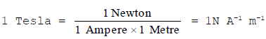
Thus, magnetic field strength (B) is defined as the force acting per unit current per unit length of a conductor placed perpendicular to the direction of the magnetic field.
SI unit of magnetic field strength is Tesla.
|
80 videos|569 docs|80 tests
|
FAQs on Force on a Current Carrying Conductor & Fleming's Left & Right Hand Rule - Science Class 10
| 1. What is Fleming's Left Hand Rule and how is it applied to find the direction of force on a current-carrying conductor in a magnetic field? |  |
| 2. What factors affect the magnitude of the force on a current-carrying conductor placed in a magnetic field? | |
| 3. How does Fleming's Right Hand Rule differ from Fleming's Left Hand Rule? | |
| 4. What is the formula to calculate the force on a current-carrying conductor in a magnetic field? | |
| 5. Can you provide an example of a practical application of the force on a current-carrying conductor in a magnetic field? | |


Viva Questions
,Force on a Current Carrying Conductor & Fleming's Left & Right Hand Rule | Science Class 10
,Previous Year Questions with Solutions
,practice quizzes
,MCQs
,video lectures
,Force on a Current Carrying Conductor & Fleming's Left & Right Hand Rule | Science Class 10
,Sample Paper
,Semester Notes
,Free
,ppt
,Important questions
,Objective type Questions
,Force on a Current Carrying Conductor & Fleming's Left & Right Hand Rule | Science Class 10
,mock tests for examination
,shortcuts and tricks
,Summary
,Exam
,past year papers
,Extra Questions
,study material
;


Force on a Current Carrying Conductor & Fleming's Left & Right Hand Rule Free PDF Download
Importance of Force on a Current Carrying Conductor & Fleming's Left & Right Hand Rule
Force on a Current Carrying Conductor & Fleming's Left & Right Hand Rule Notes
Force on a Current Carrying Conductor & Fleming's Left & Right Hand Rule Class 10 Questions
Study Force on a Current Carrying Conductor & Fleming's Left & Right Hand Rule on the App
|
© EduRev
|
Education Revolution
|


|


