NEET Previous Year Questions (2014-2025): Current Electricity | Physics Class 12 PDF Download

From 2014 to 2025, 67 questions were asked on electrical circuits, resistance, and related concepts in the NEET exams. The distribution of questions varied across the years, with an average of about 5-6 questions per year, peaking at 14 questions in 2024 and dropping to 3 questions in both 2017 and 2025. Questions appeared consistently across all years, with notable increases in 2022 (12 questions), 2023 (10 questions), and 2024 (14 questions). The questions primarily focused on topics such as Ohm’s Law, series and parallel circuits, Kirchhoff’s laws, potentiometer applications, Wheatstone bridge, drift velocity, and resistance properties (e.g., temperature coefficient, color coding). Specific areas included calculations of equivalent resistance, current and voltage in circuits, and properties of conductors and semiconductors. 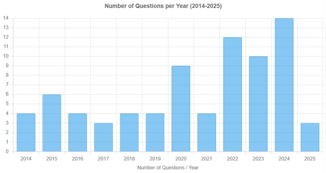
2025
Q1: The current passing through the battery in the given circuit, is: [NEET 2025]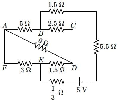 (a) 2.5 A
(b) 1.5 A
(c) 2.0 A
(d) 0.5 A
 View Answer
Ans: (d)
1. Between B and C: 2.5 Ω
Between C and D: 1.5 Ω
Total resistance in B-C-D path = 2.5 + 1.5 = 4 Ω
2. Between B and E: 6 Ω
Between E and D: 1.5 Ω
Total resistance in B-E-D path = 6 + 1.5 = 7.5 Ω
3. The two paths B–C–D and B–E–D are in parallel:
1/R = 1/4 + 1/7.5
1/R = (7.5 + 4) / (4 × 7.5) = 11.5 / 30
R = 30 / 11.5 ≈ 2.61 Ω
4. Add all resistances in series from A to F via B and D:
A–B = 5 Ω
B–D (equivalent) = 2.61 Ω
D–F = 1/3 Ω
F–A = 3 Ω
5. Total Resistance = 5 + 2.61 + 1/3 + 3
= 5 + 2.61 + 0.33 + 3 = 10.94 Ω
Rounded simplification gives approximately 10 Ω.
6. Apply Ohm's Law:
I = V / R = 5 / 10 = 0.5 A
Q2: A wire of resistance R is cut into 8 equal pieces. From these pieces two equivalent resistance are made by adding four of these together in parallel. Then these two sets are added in series. The net effective resistance of the combination is: [NEET 2025]
(a) R/16
(b) R/8
(c) R/64
(d) R/32
View Answer Ans: (a)
After being cut into 8 equal pieces,
⇒ Resistance of each piece = R′ = R / 8
Each set has 4 pieces in parallel combination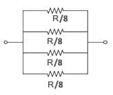
1 / R'' = 8 / R + 8 / R + 8 / R + 8 / R
⇒ Resistance of each set = R″ = R / 32
Both sets are connected in series
∴ Req = R″ + R″ = 2 × (R / 32) = R / 16
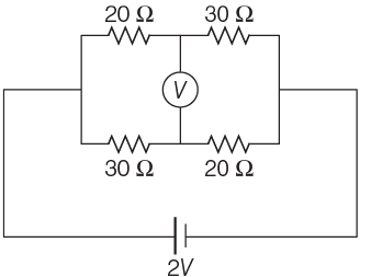
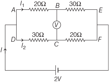
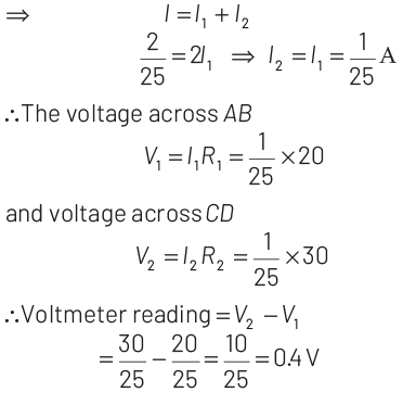
Q3: A constant voltage of 50 V is maintained between the points A and B of the circuit shown in the figure. The current through the branch CD of the circuit is: [NEET 2025]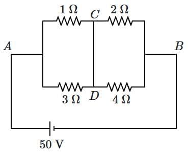 (a) 2.5 A
(b) 3.0 A
(c) 1.5 A
(d) 2.0 A
View Answer Ans: (d)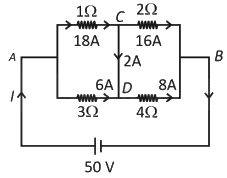 RAB = (1Ω // 3Ω) in series with (2Ω // 4Ω)
⇒ (1 × 3) / (1 + 3) + (2 × 4) / (2 + 4)
= 3 / 4 + 8 / 6 = (9 + 16) / 12 = 25 / 12 Ω
Now total current through the cell
I = 50 / (25 / 12) = 24 A
I1Ω = (3 / 4) × 24 = 18 A, I3Ω = (1 / 4) × 24 = 6 A
I2Ω = (4 / 6) × 24 = 16 A, I4Ω = (2 / 6) × 24 = 8 A
Using junction rule at C,
ICD = 18 − 16 = 2 A (from C to D)
2024
Q1: The terminal voltage of the battery, whose emf is 10V and internal resistance 1Ω, when connected through an external resistance of 4Ω as shown in the figure is: [NEET 2024]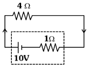 (a) 4 V
(b) 6 V
(c) 8 V
(d) 10 V
View Answer Ans: (c)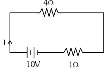 Current in circuit
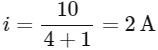
Terminal voltage = E - iR
= 10 - 2 x 1 = 8 V
Q2: A wire of length 'l' and resistance 100Ω is divided into 10 equal parts. The first 5 parts are connected in series while the next 5 parts are connected in parallel. The two combinations are again connected in series. The resistance of this final combination is: [NEET 2024]
(a) 26Ω
(b) 52Ω
(c) 55Ω
(d) 60Ω
View Answer Ans:(b)
To solve this problem, we first need to understand how the resistance changes when we cut the wire into equal parts and how it behaves when connected in different configurations (series and parallel).
Given:
Original length of the wire, l.
Total resistance of the wire R = 100Ω.
The wire is divided into 10 equal parts.
Resistance of each part:
Since the wire is divided into 10 equal parts, the length of each part is l/10. Resistance is proportional to length (as long as the cross-sectional area and material of the wire remain constant). Therefore, the resistance of each part, denoted as r, is 1/10th of the total resistance:
First 5 parts in series:
When resistors are connected in series, the total resistance is the sum of the individual resistances:
Next 5 parts in parallel:
When resistors are connected in parallel, the total resistance parallel Rparallel can be calculated using the reciprocal formula:
Thus,
Rparallel = 2Ω
Final combination in series:
The total resistance of the combination, where the series and parallel groups are again connected in series, will be: Thus, the correct answer to the resistance of the final combination is:
Option B: 52Ω
Q3: Choose the correct circuit which can achieve the bridge balance.
(a) 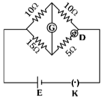
(b) 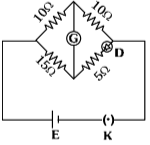
(c) 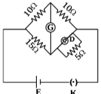
(d) 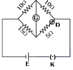 [NEET 2024]
View Answer Ans: (a)
In option (a),
The diode can conduct and have resistance RD = 10Ω because diode have dynamic resistance. In that case bridge will be balanced.
Q4: Two heaters A and B have power rating of 1 kW and 2 kW, respectively. Those two are first connected in series and then in parallel to a fixed power source. The ratio of power outputs for these two cases is:
(a) 1 : 1
(b) 2 : 9
(c) 1 : 2
(d) 2 : 3 [NEET 2024]
View Answer Ans:(b)
To find the ratio of power outputs when two heaters with different power ratings are connected first in series and then in parallel, we need to understand how the total power output varies based on the type of connection.
Heater Specifications:
- Power of heater A
kWW(PA) - Power of heater B
kWW(PB)
Scenario 1: Series Connection
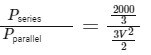
When resistors (or heaters in this case) are connected in series, the total resistance (Rseries
Using the formula for electrical power: P = V2 / R,
where P is power, V is voltage, and R is resistance, we can express the resistance of each heater as:
Substitute the given power values: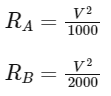
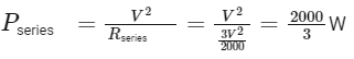
Then the total resistance for the series connection is:
The total power output in series (Pseries) is:
Scenario 2: Parallel Connection
For parallel connections, the total resistance (Rparallel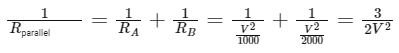
Reformulate to find Rparallel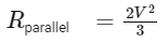
And the total power output in parallel (P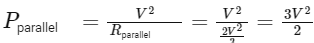
However, simplifying,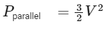
The ratio of powers is then:
Solving and simplifying,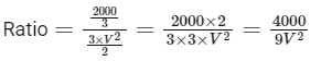
Given that we know one ratio of the actual power values, we simplify further. For calculating power in simple terms, consider voltage to be normalized (taken out of the fraction):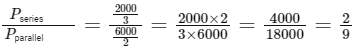
Therefore, the ratio of the power outputs when the heaters are connected first in series and then in parallel is 2:9, which corresponds to Option B.
Q5: The equivalent resistance RAB between points A and B in the given network is: [NEET 2024]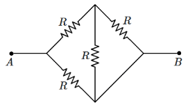 (a) 1R
(b) 3/5R
(c) 7/8R
(d) 5/8R
View Answer Ans: (a)
To find the equivalent resistance between A and B for the given network, observe that two resistors in series (R) are connected in parallel with two other resistors in series (R). This is a combination of series and parallel connections.
- The two resistors in series will have a combined resistance of 2R.
- The equivalent resistance of these two resistors (2R) is in parallel with the other two resistors in series (2R).
To find the total equivalent resistance between A and B:
1/Req = 1/(2R) + 1/(2R)
Req = R.
So, the correct answer is (a) 1R.
Q6: The value of R in the given circuit when there is no current in the 5 Ω resistor is: [NEET 2024]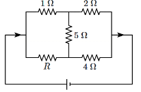 (a) 12 Ω
(b) 9 Ω
(c) 3 Ω
(d) 2 Ω
View Answer Ans: (d)
In this circuit, the condition is given that there is no current in the 5Ω resistor. For this to happen, the potential difference across the 5Ω resistor must be zero, meaning the two resistors (R and the 5Ω) must be in parallel and the total voltage across them is zero.
To ensure this, the equivalent resistance (R) should be calculated to balance the circuit. Solving this gives R = 2Ω.
Thus, the correct answer is (d) 2Ω.
Q7: There are two heaters A and B. The heater A takes time t₁ to boil a given quantity of water, while B takes time t₂ to boil the same quantity of water across the same supply voltage. If the two heaters are connected in series, the time taken by this combination to boil the same quantity of water will be: [NEET 2024]
(a) t₁t₂ / (t₁ + t₂)
(b) t₁ + t₂
(c) 1/2 (t₁ + t₂)
(d) t₁t₂ / 2(t₁ + t₂)
View Answer Ans: (b)
To understand this problem, let's recall the concept of the relationship between power, time, and energy. The power consumed by each heater is inversely related to the time taken to boil the same amount of water.
The energy required to heat a specific amount of water is the same for both heaters, and it’s given by the equation:
Energy (E) = Power (P) × Time (t).
Now, when two heaters are connected in series, the total resistance increases (since the resistances of the two heaters add up), and this results in a decrease in the overall power. As power is inversely proportional to time for the same amount of energy, the time taken to boil the water will increase.
However, the total time taken is the sum of the individual times when two resistances are connected in series. Thus, the time taken by the combination of heaters A and B to boil the same quantity of water is the sum of the times for each heater when they are connected individually.
Hence, the correct answer is: (b) t₁ + t₂.
Q8: Arrange the following in the order of their resistance: [NEET 2024]
A. (0 to 1 A) ranged ammeter
B. (0 to 100 mA) ranged milli-ammeter
C. (0 to 500 μA) ranged micro-ammeter
D. (0 to 100 V) ranged voltmeter
Choose the correct answer from the options given below:
(a) A > B > C > D
(b) D > C > B > A
(c) C > B > A > D
(d) D > C > A > B
View Answer Ans: (b)
The resistance of a meter (ammeter or voltmeter) is inversely related to its range for the same given quantity (current or voltage). In general:
Voltmeters have a high resistance because they need to measure large voltage differences with minimal current flow. Therefore, the voltmeter (D) will have the highest resistance.
Micro-ammeters (C), which measure lower currents (in the microampere range), will have a higher resistance than milli-ammeters (B), which measure currents in the milliampere range.
Ammeter (A), which measures current in the range of 0 to 1 A, will have the lowest resistance.
Thus, the correct order of increasing resistance is: D > C > B > A
Q9: A uniform wire of diameter d carries a current of 100 mA when the mean drift velocity of electrons in the wire is v. For a wire of diameter d/2 = 2d of the same material to carry a current of 200 mA, the mean drift velocity of electrons in the wire is:
(a) 4v
(b) 8v
(c) v
(d) 2v [NEET 2024]
View Answer Ans: (b)
We know that the current (I) in a wire is related to the drift velocity (v) and the cross-sectional area (A) of the wire by the formula:
I = n A e v
Where:
- I is the current,
- n is the number of charge carriers,
- A is the cross-sectional area of the wire,
- e is the charge of an electron,
- v is the drift velocity.
The area of the wire is related to its diameter (d). The formula for the area (A) of the wire is:
A = π × d² / 4
Step 1: First wire
- The current in the first wire is 100 mA.
- The diameter of the wire is d, and the drift velocity is v. So, the equation for the first wire is:
100 mA = n × (π × d² / 4) × e × v
Step 2: Second wire
- The current in the second wire is 200 mA.
- The diameter of the second wire is d/2, so its area will be π × (d/2)² / 4 = π × d² / 16.
- We need to find the drift velocity (v₂) for this second wire. So, the equation for the second wire is:
200 mA = n × (π × d² / 16) × e × v₂
Step 3: Comparing the two equations
By comparing the two equations, we see that the current is proportional to the area and drift velocity. We can set up the ratio:
(200 / 100) = (Area of second wire × drift velocity of second wire) / (Area of first wire × drift velocity of first wire)
Simplifying:
2 = (π × d² / 16 × v₂) / (π × d² / 4 × v)
This simplifies further to: 2 = v₂ / (4 × v)
So, v₂ = 8v.
Final answer: The drift velocity in the second wire is 8 times the drift velocity in the first wire. So, the correct answer is: (b) 8v.
Q10: In an electrical circuit, the voltage is measured as V = (200 ± 4) volts and the current is measured as I = (20 ± 0.2) A. The value of the resistance is: [NEET 2024]
(a) (10 ± 4.2) Ω
(b) (10 ± 0.3) Ω
(c) (10 ± 0.1) Ω
(d) (10 ± 0.8) Ω
View Answer Ans: (b)
Using Ohm's Law:
R = V / I
Given:
V = (200 ± 4) V
I = (20 ± 0.2) A
The calculated resistance: R = 200 V / 20 A = 10 Ω
To find the uncertainty in R, we apply error propagation: ΔR = R × √[(ΔV/V)² + (ΔI/I)²]
Where:
ΔV = 4 V
ΔI = 0.2 A
Substituting the values: ΔR = 10 × √[(4/200)² + (0.2/20)²]
= 10 × √[0.0004 + 0.0001]
= 10 × √0.0005 ≈ 0.3 Ω
Therefore, the resistance is R = 10 ± 0.3 Ω.
So, the correct answer is (b) (10 ± 0.3) Ω.
Q11: A uniform metal wire of length l has 10 Ω resistance. Now this wire is stretched to a length 2l and then bent to form a perfect circle. The equivalent resistance across any arbitrary diameter of that circle is: [NEET 2024]
(a) 10 Ω
(b) 5 Ω
(c) 40 Ω
(d) 20 Ω
View Answer Ans: (a)
Given:
Original length of wire = l
Original resistance = 10 Ω
Wire is stretched to length = 2l
Then bent into a circular loop.
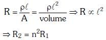
When a wire is stretched:
Volume remains constant (V = A × L, where A = cross-sectional area, L = length).
If length doubles (new length = 2l), area reduces to half (new area = A/2).
Resistance formula:
R = ρ × (L / A)
New resistance after stretching:
Rnew = ρ × (2l / (A/2)) = 4 × ρ × (l / A) = 4 × 10 Ω = 40 Ω
Total resistance of stretched wire = 40 Ω
The wire is bent into a circle with circumference = 2l.
The circle has two semicircular arcs, each of length = l.
Resistance of each semicircular arc = 40 Ω / 2 = 20 Ω
Equivalent resistance across diameter:
The two semicircular arcs are in parallel (since current splits at the diameter endpoints).
Equivalent resistance:
Req = (20 Ω × 20 Ω) / (20 Ω + 20 Ω) = 400 / 40 = 10 Ω
Q12: The given circuit shows a uniform straight wire AB of 40cm length fixed at both ends. In order to get zero reading in the galvanometer G, the free end of J is to be placed from the end B at: [NEET 2024]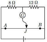 (a) 32 cm
(b) 8 cm
(c) 16 cm
(d) 24 cm
View Answer Ans: (d)
Step-by-step solution:
Given information:
The length of the wire AB = 40 cm.
Two resistors, 8 Ω and 12 Ω, are connected to the wire, and the wire is fixed at both ends A and B.
We need to find the position where the free end J should be placed such that the galvanometer reading is zero.
Concept of null deflection:
For zero current to flow through the galvanometer, the potential difference across it must be zero.
This occurs when the ratio of the lengths of the wire segment from A to J (where the galvanometer is connected) and from J to B is such that the potential drop in the 8 Ω and 12 Ω resistors balance each other.
Using the principle of potential division:
The potential drop across a resistor is proportional to its resistance.
Let the length AJ = x cm and the length JB = (40 - x) cm.
The potential drop in the 8 Ω resistor is proportional to x and the potential drop in the 12 Ω resistor is proportional to (40 - x).
Setting up the equation:
The voltage drop across 8 Ω should balance the voltage drop across 12 Ω: (8 Ω) × (x / 40)
= (12 Ω) × ((40 - x) / 40)
Simplifying:
8x = 12(40 - x)
8x = 480 - 12x
8x + 12x = 480
20x = 480
x = 480 / 20
x = 24 cm
Final answer: The free end of the galvanometer should be placed at 24 cm from the end B for zero reading on the galvanometer.
Correct answer: (d) 24 cm.
Q13: The amplitude of the charge oscillating in a circuit decreases exponentially as Q = Q₀ e(-Rt/2L) where Q₀ is the charge at t = 0 s. The time at which charge amplitude decreases to 0.50 Q₀ is nearly: [NEET 2024]
(Given that R = 1.5Ω, L = 12mH,ln(2) = 0.693)
(a) 19.01 ms
(b) 11.09 ms
(c) 19.01 s
(d) 11.09 s
View Answer Ans: (b)
Given the formula for the charge oscillation:
Q = Q₀ e(-Rt/2L)
Where:
R = 1.5 Ω (resistance)
L = 12 mH = 12 × 10⁻³ H (inductance)
ln(2) = 0.693
The charge decreases to 0.50 Q₀, so: 0.50 Q₀ = Q₀ e(-Rt/2L)
Simplifying: 0.50 = e(-Rt/2L)
Taking the natural logarithm of both sides:
ln(0.50) = -Rt/2L
Substitute the values: ln(0.50) = -0.693
So:
-0.693 = -Rt / (2 × 12 × 10⁻³)
Rearranging to solve for time t:
t = (0.693 × 2 × 12 × 10⁻³) / 1.5
t = (0.693 × 24 × 10⁻³) / 1.5
t ≈ 11.09 ms
Thus, the correct answer is (b) 11.09 ms.
Q14: The steady-state current in the circuit shown below is: [NEET 2024]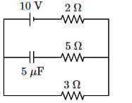 (a) 0.67 A
(b) 1.5 A
(c)2 A
(d) 1 A
View Answer Ans: (c)
To find the steady-state current in the circuit, we ignore the capacitor because, in the steady state, it behaves like an open circuit (i.e., no current flows through it).
Now, we are left with just the resistors in the circuit.
First, calculate the total resistance of the parallel resistors:
The resistors of 5Ω and 3Ω are in parallel.
The formula for the equivalent resistance of two parallel resistors is:
1 / Rparallel = 1 / 5 + 1 / 3 1 / Rparallel
= (3 + 5) / 15 = 8 / 15 Rparallel
= 15 / 8
= 1.875Ω
Now, the total resistance of the circuit is the sum of the 2Ω resistor and the 1.875Ω from the parallel combination:
Rtotal = 2Ω + 1.875Ω
= 3.875Ω
Using Ohm's law (V = IR), the total current (I) is:
I = V / Rtotal = 10V / 3.875Ω ≈ 2.58A
Thus, the correct answer is (c) 2 A.
2023
Q1: If the galvanometer G does not show any deflection in the circuit shown, the value of R is given by [NEET 2023]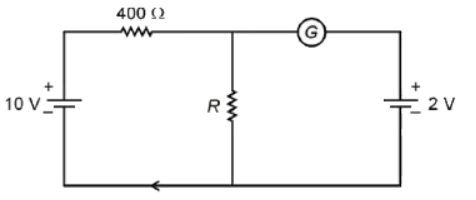 (a) 200 Ω
(b) 50 Ω
(c) 100 Ω
(d) 400 Ω
View Answer Ans: (c)
Since the galvanometer does not show any deflection, the potential of each point can be found easily as shown in the image below: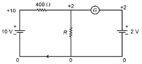 i400=(10-2)/400 =8/400= 1/50 A
The current through R will also be the same as no current is flowing through the other side.
iR=1/50 A
R=VR/IR = (2-0)/(1/50)=100Ω
Q2: Resistance of a carbon resistor determined from color codes is (22000 ± 5%) Ω. The colour of the third band must be [NEET 2023]
(a) Red
(b) Green
(c) Orange
(d) Yellow
View Answer Ans: (c)
Resistance = (22 × 103) Ω ± 5%
The third band corresponds to the decimal multiplier.
Decimal multiplier = 103
⇒ Colour → Orange
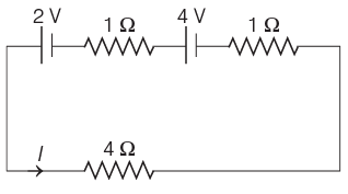
Q3: The magnitude and direction of the current in the following circuit is [NEET 2023]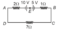
(a) 0.2 A from B to A through E
(b) 0.5 A from A to B through E
(c) 5/9 A from A to B through E
(d) 1.5 A from B to A through E
View Answer Ans: (b)
In the given image, the net current will flow from A to B because 10V > 5V.
Applying KVL from A to B to C to D we get,
-2i+10-5-1i-7i=0
5-10i=0
i=1/2 A
i=0.5 A
In clockwise direction (from A to B)
Q4: 10 resistors, each of resistance R are connected in series to a battery of emf E and negligible internal resistance. Then those are connected in parallel to the same battery, the current is increased n times. The value of n is [NEET 2023]
(a) 10
(b) 100
(c) 1
(d) 1000
View Answer Ans: (b)
In series combination
Req = 10R
In parallel combination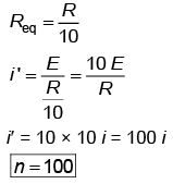
Q5: The resistance of platinum wire at 0°C is 2 Ω and 6.8 Ω at 80°C. The temperature coefficient of resistance of the wire is [NEET 2023]
(a) 3 × 10⁻⁴ °C–1
(b) 3 × 10⁻³ °C–1
(c) 3 × 10⁻² °C–1
(d) 3 × 10⁻¹ °C–1
View Answer Ans: (c)
Using R = R0(1 + αΔT)
where a is the thermal coefficient of resistance
6.8 = 2{1 + α(80 - 0)}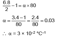
Q6: A certain wire A has a resistance of 81 Ω. The resistance of another wire B of the same material and equal length but of diameter thrice the diameter of A will be : [NEET 2023]
(a) 81 Ω
(b) 9 Ω
(c) 729 Ω
(d) 243 Ω
View Answer Ans: (b)
If the diameter becomes thrice then the cross-section area will become 9 times so
Resistance will become 1/9 times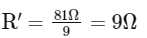
Q7: To produce an instantaneous displacement current of 2 mA in the space between the parallel plates of a capacitor of capacitance 4μF, the rate of change of applied variable potential difference (dv/dt) must be [NEET 2023]
(a) 800 V/s
(b) 500 V/s
(c) 200 V/s
(d) 400 V/s
View Answer Ans: (b)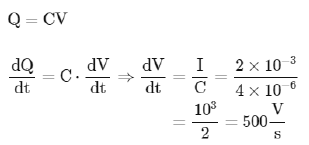
Q8: On the basis of electrical conductivity, which one of the following materials has the smallest resistivity? [NEET 2023]
(a) Germanium
(b) Silver
(c) Glass
(d) Silicon
View Answer Ans: (b)
The resistivity of a material is inversely related to its electrical conductivity. The material with the smallest resistivity will have the highest electrical conductivity. Among the options:
Germanium and Silicon are semiconductors with higher resistivity compared to conductors.
Silver is one of the best conductors of electricity, and it has the lowest resistivity among common materials.
Glass is an insulator and has a much higher resistivity compared to metals and semiconductors.
Thus, Silver has the smallest resistivity and is the best conductor among the listed materials.
Q9: A copper wire of radius 1 mm contains 1022 free electrons per cubic metre. The drift velocity for free electrons when 10A current flows through the wire will be:
(Given, charge on electron = 1.6 × 10⁻¹⁹ C) [NEET 2023]
(a) 6.25 × 10⁴ / π m/s
(b) 6.25 / π × 10³ m/s
(c) 6.25 / π m/s
(d) 6.25 × 10⁵ / π m/s
View Answer Ans: (b)
To find the drift velocity, we can use the formula for drift velocity:
I = n × A × e × vd
Where:
I is the current (10 A),
n is the number of free electrons per unit volume (1 × 10²² electrons/m³),
A is the cross-sectional area of the wire,
e is the charge of an electron (1.6 × 10⁻¹⁹ C),
vd is the drift velocity.
First, let's calculate the cross-sectional area (A) of the wire:
The radius of the wire is given as 1 mm = 1 × 10⁻³ m.
The area of the cross-section (A) of the wire is given by the formula: A = π × r², where r is the radius of the wire.
A = π × (1 × 10⁻³ m)² = π × 10⁻⁶ m²
Now, rearranging the drift velocity formula to solve for v_d:
vd = I / (n × A × e)
Substitute the known values:
vd = 10 A / (1 × 10²² electrons/m³ × π × 10⁻⁶ m² × 1.6 × 10⁻¹⁹ C)
Simplifying the expression:
vd= 10 / (1.6 × 10⁻² × π)
vd ≈ 6.25 × 10³ / π m/s
Thus, the correct answer is (b) 6.25 / π × 10³ m/s.
Q10: The emf of a cell having internal resistance 1 Ω is balanced against a length of 330 cm on a potentiometer wire. When an external resistance of 2 Ω is connected across the cell, the balancing length will be: [NEET 2023]
(a) 220 cm
(b) 330 cm
(c) 115 cm
(d) 332 cm
View Answer Ans: (a)
The potential difference across the cell is given by:
V = E - I × r
Where:
E is the emf of the cell,
I is the current,
r is the internal resistance of the cell.
When an external resistance R is connected, the total resistance in the circuit becomes (R + r), and the current I' is given by:
I' = E / (R + r)
Since the potentiometer is used to measure the potential difference, the balancing length will be proportional to the potential difference.
The new potential difference across the cell with the external resistance connected is:
V' = I' × r
The new balancing length is the ratio of the new potential difference to the original potential difference. Since the current decreases when the external resistance is added, the balancing length will decrease as well. Based on the current distribution, the balancing length will be 220 cm.
Therefore, the correct answer is (a) 220 cm.
2022
Q1: The reciprocal of resistance is :
(a) conductance
(b) reactance
(c) mobility
(d) conductivity
View Answer Ans: (a)
R = 1/G
Thus reciprocal of resistance (R) is conductance (G)
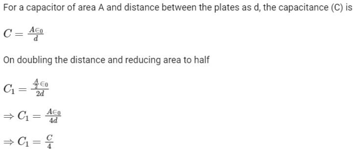
Q2: The distance between the two plates of a parallel plate capacitor is doubled and the area of each plate is halved. If C is its initial capacitance, its final capacitance is equal to
(a) C/4
(b) 2C
(c) C/2
(d) 4C
View Answer Ans:(a)
Q3: A cell of emf 4 V and internal resistance 0.5 Ω is connected to a 7.5 Ω external resistance. The terminal potential difference of the cell is
(a) 0.375 V
(b) 3.75 V
(c) 4.25 V
(d) 4V
View Answer Ans:(b)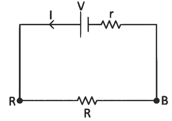 From Kirchhoff's loop law :
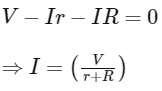
Terminal potential difference across cell,
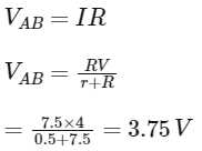
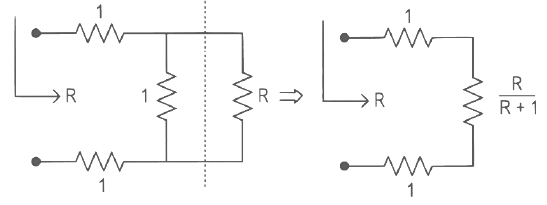
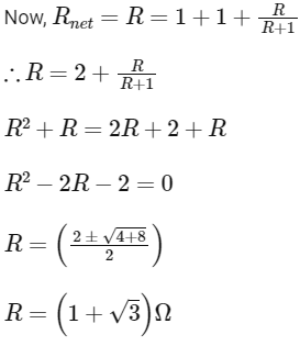
Q4: The equivalent resistance of the infinite network given below is :
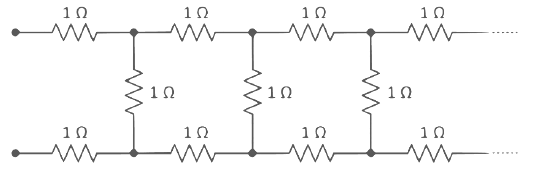
(a) 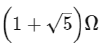
(b) 2 Ω
(c) 
(d) 
View Answer Ans:(d)
Let net resistance of the given infinite network be 'R'
Now, the circuit can be modified as
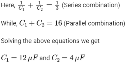
Q5: The effective capacitances of two capacitors are 3 μF and 16 μF, when they are connected in series and parallel respectively. The capacitance of two capacitors are :
(a) 1.2 μF, 1.8 μF
(b) 10μF, 6 μF
(c) 8 μF, 8 μF
(d) 12 μF, 4 μF
View Answer Ans: (d)
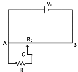
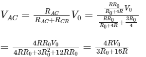
Q6: The sliding contact C is at one fourth of the length of the potentiometer wire (AB) from A as shown in the circuit diagram. If the resistance of the wire AB is R0, then the potential drop (V) across the resistor R is
 (a)
(a) 
(b) 
(c) 
(d) 
View Answer Ans: (b)
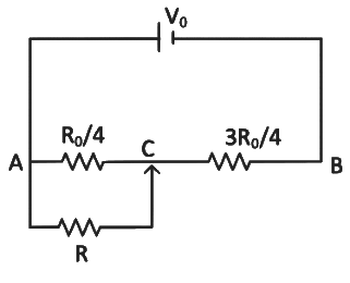
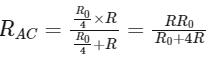
Equivalent resistance across point AC
From voltage divider rule
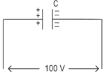
Q7: A capacitor of capacitance C = 900 pF is charged fully by 100 V battery B as shown in figure (a). Then it is disconnected from the battery and connected to another uncharged capacitor of capacitance C = 900 pF as shown in figure (b). The electrostatic energy stored by the system (b) is
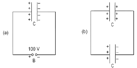
(a) 4.5 x 10⁻⁶ J
(b) 3.25 x 10⁻⁶ J
(c) 2.25 x 10⁻⁶ J
(d) 1.5 x 10⁻⁶ J
View Answer Ans: (c)
q1 = CV
= 900 x 10-12 x 100
= 9 x 10⁻⁸ J
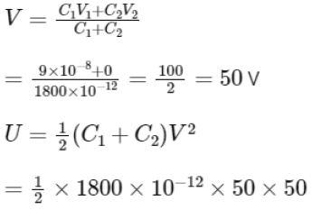
= 225 x 10-8
U = 2.25 x 10⁻⁶ J
Q10: A copper wire of length 10 m and radius (10−2/√π) m has an electrical resistance of 10 Ω. The current density in the wire for an electric field strength of 10 (V/m) is:
(a) 106 A/m2
(b) 10–5 A/m2
(c) 105 A/m2
(d) 104 A/m2
View Answer Ans: (c)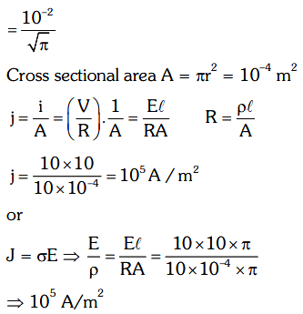
Q11: A Wheatstone bridge is used to determine the value of unknown resistance X by adjusting the variable resistance Y as shown in the figure. For the most precise measurement of X, the resistances P, and Q 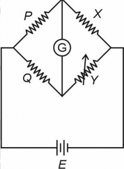 (a) Should be approximately equal and are small
(b) Should be very large and unequal
(c) Do not play any significant role
(d) Should be approximately equal to 2X
View Answer Ans: (a)
We know, a Wheatstone bridge is said to be most precise when it is most sensitive. This can be done by making the ratio of arms equal. Thus (1) is the correct option.
Q12: Two resistors of resistance, 100 Ω and 200 Ω are connected in parallel in an electrical circuit. The ratio of the thermal energy developed in 100 Ω to that in 200 Ω in a given time is
(a) 2 : 1
(b) 1 : 4
(c) 4 : 1
(d) 1 : 2
View Answer Ans: (a)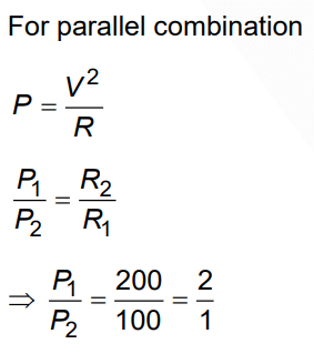
Q13: As the temperature increases, the electrical resistance
(a) Decreases for both conductors and semiconductors
(b) Increases for conductors but decreases for semiconductors
(c) Decreases for conductors but increases for semiconductors
(d) Increases for both conductors and semiconductors
View Answer Ans:(b)
As the temperature increases, the resistivity of the conductor increases hence the electrical resistance increases. However, for semiconductors, the resistivity decreases with the temperature. Hence the electrical resistance of semiconductors decreases.
2021
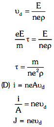
Q1: Column Igives certain physical terms associated with the flow of current through a metallic conductor.
Column IIgives some mathematical relations involving electrical quantities.
Match Column-I and Column-IIwith appropriate relations. (2021)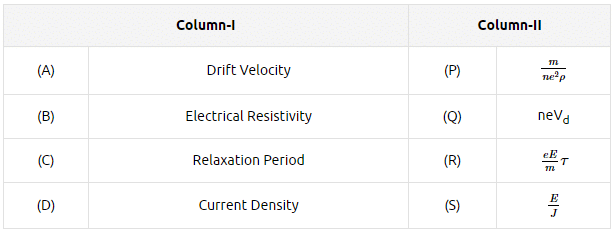
(a) (A)-(R), (B)-(P), (C)-(S), (D)-(Q)
(b) (A)-(R), (B)-(Q), (C)-(S), (D)-(P)
(c) (A)-(R), (B)-(S), (C)-(P), (D)-(Q)
(d) (A)-(R), (B)-(S), (C)-(Q), (D)-(P)
View Answer Ans: (c)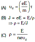
Q2: In a potentiometer circuit, a cell of EMF 1.5 V gives a balance point at 36 cm length of wire. If another cell of EMF 2.5 V replaces the first cell, then at what length of the wire, does the balance point occur?
(a) 64 cm
(b) 62 cm
(c) 60 cm
(d) 21.6 cm
View Answer Ans: (c)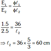
Q3: The effective resistance of a parallel connection that consists of four wires of equal length, equal area of cross-section, and the same material is 0.25Ω. What will be the effective resistance if they are connected in series?
(a) 1Ω
(b) 4Ω
(c) 0.25Ω
(d) 0.5Ω
View Answer Ans: (b)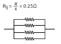
R = 1Ω
Rseries = 4R
= 4(1)
= 4Ω.
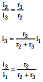
Q4: Three resistors having resistances r1, r2, and r3 are connected as shown in the given circuit. The ratio i3/i1of currents in terms of resistances used in the circuit are: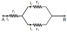
(a) 
(b) 
(c) 
(d) 
View Answer Ans: (d)
v = ir
i = v/r
i ∝ i/r
[ v is same for r2 & r3]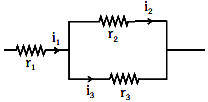
2020
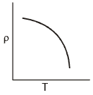
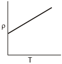
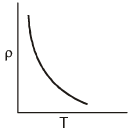
Q1: Which of the following graphs represents the variation of resistivity (r) with temperature (T) For copper? (a)
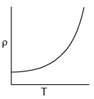
(b)
(c)
(d)
 View Answer
 Ans: (a)
The relation between resistivity and temperature is given by ρ = ρ0e-αT
Q2: A charged particle having drift velocity of 7.5×10⁻⁴ m s-1 in an electric field of 3×10⁻¹⁰ Vm-1 has a mobility in m2 V-1 s-1 of : .
(a) 2.5×10⁻⁶
(b) 2.25×10⁻¹⁵
(c) 2.25×10¹⁵
(d) 2.5×10⁶
View Answer Ans: (d)
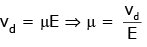
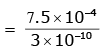
μ = 2.5 × 10⁶
(μ = mobility)
Q3: The color code of resistance is given below:
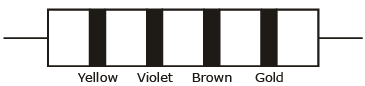
The values of resistance and tolerance, respectively, are :
(a) 4.7 kΩ, 5%
(b) 470Ω, 5%
(c) 470 kΩ, 5%
(d) 47 kΩ, 10%
View Answer Ans: (b)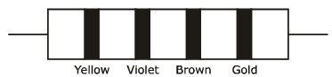
 R = 47 × 101Ω ± 5%
= 470 Ω ± 5%
So, 470, 5%
Q4: The solids which have the negative temperature coefficient of resistance are :
(a) semiconductors only
(b) insulators and semiconductors
(c) metals
(d) insulators only
View Answer Ans: (b)
Insulators have a negative temperature coefficient because as temperature increases, the resistance of insulators decreases. The resistivity of the semiconductor material decreases with the rise in temperature, resulting in a negative temperature coefficient of resistance.
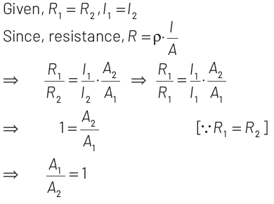
Q5: Two solid conductors are made up of same material, have same length and same resistance. One of them has a circular cross-section of area A1 and the other one has a square cross-section of area A2 .
The ratio A1 / A2
(a) 1.5
(b) 1
(c) 0.8
(d) 2
View Answer Ans: (b)
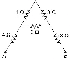
Q6: The equivalent resistance between A and B for the mesh shown in the figure is
 (a) 7.2 Ω
(b) 16 Ω
(c) 30 Ω
(d) 4.8 Ω
View Answer Ans: (b)
Equivalent resistance between points A and B is given as
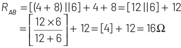
Q7: For the circuit shown in the figure, the current I will be
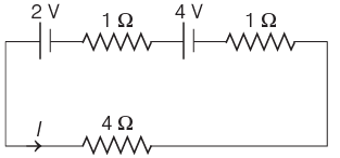 (a) 0.75 A
(b) 1 A
(c) 1.5 A
(d) 0.5 A
View Answer Ans:(b)
The circuit diagram is shown below
Applying KVL in the loop, we get
4I + I⋅1 −4+ I⋅1 −2 =0
⇒ 6I = 6
⇒ I = 1 A
Q8: For the circuit given below, the Kirchhoff’s loop rule for the loop BCDEB is given by the equation
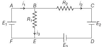
View Answer Ans: (b)
The circuit diagram is given below
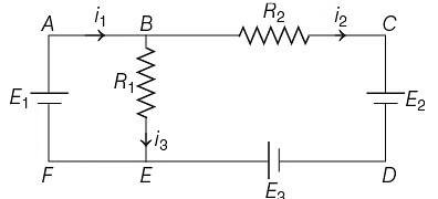
Applying KVL rule in loop BCDEB,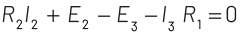
Q9: A resistance wire connected in the left gap of a metre bridge balances a 10 Ω resistance in the right gap at a point which divides the bridge wire in the ratio 3 : 2. If the length of the resistance wire is 1.5 m, then the length of 1 Ω of the resistance wire is
(a) 1.0 × 10⁻¹ m
(b) 1.5 × 10⁻¹ m
(c) 1.5 × 10⁻² m
(d) 1.0 × 10⁻² m
View Answer Ans:(a)
According to the question, the metre bridge is shown below,
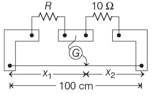
Given, 
At balance condition in metre bridge,
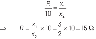
Now, length of given wire whose resistance 15 Ω is 1.5 m.
Therefore, length of 1Ω resistance wire is
= 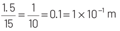
Hence, correct option is (a).
2019
Q1: Six similar bulbs are connected as shown in the figure with a DC source of emf E and zero internal resistance.
The ratio of power consumption by the bulbs when (i) all are glowing and (ii) in the situation when two from section A and one from section B are glowing, will be :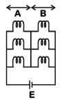
(a) 4 : 9
(b) 9 : 4
(c) 1 : 2
(d) 2 : 1
View Answer Ans: (b)
Solution:
(i) All bulbs are glowing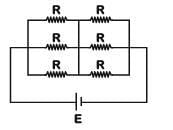
(ii) Two from section A and one from section B are glowing.
Q2:In the circuits shown below, the readings of the voltmeters and the ammeters will be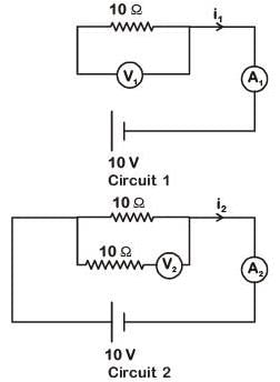
(a) V2 > V1 and i1 = i2
(b) V1 = V2 and i1 > i2
(c) V1 = V2 and i1 = i2
(d) V2 > V1 and i1 > i2
View Answer Ans: (c)
Solution:
For ideal voltmeter, resistance is infinite and for the ideal ammeter, resistance is zero.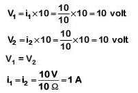
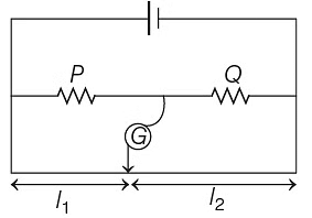
Q3: The meter bridge shown in the balance position with P/Q = l1 / l2. If we now interchange the positions of galvanometer and cell, will the bridge work? If yes, that will be balanced condition?
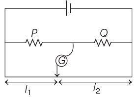
(a) 
(b) no, no null point
(c) 
(d) 
View Answer Ans: (d)
For balanced position in a meterbridge

Now, if position of G and cell is interchanged,
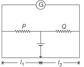
The balance condition still remains the same if the jockey points as the same point as given in the initial condition, for which there is no deflection in the galvanometer or no current will be drawn from the cell. Thus, the bridge will work as usual and balance condition is same,
P / Q = l1 /l2
Q4: The reading of an ideal voltmeter in the circuit shown is
(a) 0.6 V
(b) 0 V
(c) 0.5 V
(d) 0.4 V
View Answer Ans: (d)
The given circuit diagram can be drawn as shown below
The equivalent resistance of circuit is given by
As the resistance of two branches is same i.e. 50 Ω.
So, the current I1 = I2
2018
Q1: A set of 'n' equal resistors, of value 'R' each, are connected in series to a battery of emf 'E' and internal resistance 'R'. The current drawn is I. Now, the 'n' resistors are connected in parallel to the same battery. Then the current drawn from the battery becomes 10 I. The value of 'n' is:
(a) 10
(b) 11
(c) 20
(d) 9
View Answer Ans: (a)
Solution: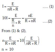
Q2: A battery consists of a variable number 'n' of identical cells (having internal resistance 'r' each) which are connected in series. The terminals of the battery are short-circuited and the current I is measured. Which of the graphs shows the correct relationship between I and n?
(a)

(b)
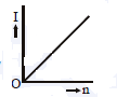
(c)

(d)

View Answer Ans: (a)
Solution: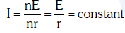
Q3: Current sensitivity of a moving coil galvanometer is 5 div/mA and its voltage sensitivity (angular deflection per unit voltage applied) is 20 div/V. The resistance of the galvanometer is
(a) 40 Ω
(b) 25 Ω
(c) 250 Ω
(d) 500 Ω
View Answer Ans: (c)
Solution: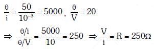
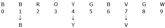
Q4: A carbon resistor of (47 ± 4.7) kΩ is to be marked with rings of different colours for its identification. The colour code sequence will be
(a) Yellow - Green - Violet - Gold
(b) Yellow - Violet - Orange - Silver
(c) Violet - Yellow - Orange - Silver
(d) Green - Orange - Violet - Gold
View Answer Ans: (b)
Given, R = (47 ± 4.7) kΩ
= 47 × 103 ± 10% Ω
As per the colour code for carbon resistors, the colour assigned to numbers.
4 – Yellow
7 – Violet
3 – Orange
For ±10% accuracy, the colour is silver.
Hence, the bands of colours on carbon resistor in sequence are yellow, violet, orange and silver.
Note To remember the colour code sequence for carbon resistor, the following sentence should be kept in memory. B B Roy of Great Britain has a Very Good Wife.
2017
Q1: The resistance of a wire is 'R' ohm. If it is melted and stretched to 'n' times its original length, its new resistance will be :
(a) R/n
(b) n2R
(c) R/n2
(d) nR
View Answer Ans: (b)
Solution:
Q2: A potentiometer is an accurate and versatile device to make electrical measurements of E.M.F. because the method involves:
(a) Potential gradients
(b) A condition of no current flow through the galvanometer
(c) A combination of cells, galvanometer, and resistances
(d) Cells
View Answer Ans: (b)
Solution:
In zero deflection conditions, the potentiometer draws no current.
Q3: A potentiometer is an accurate and versatile device to make electrical measurement of EMF because the method involves
(a) cells
(b) potential gradients
(c) a condition of no current flow through the galvanometer
(d) a combination of cells, galvanometer and resistances
View Answer Ans: (c)
When a cell is balanced against potential drop across a certain length of potentiometer wire, no current flows through the cell
∴ emf of cell = potential drop across balance length of potentiometer wire.
So, potentiometer is a more accurate device for measuring emf of a cell or no current flows through the cell during measurement of emf.
2016
Q1: A potentiometer wire is 100 cm long and a constant potential difference is maintained across it. Two cells are connected in series first to support one another and then in opposite directions. The balance points are obtained at 50 cm and 10 cm from the positive end of the wire in the two cases. The ratio of emf's is :
(a) 3:2
(b) 5:1
(c) 5:4
(d) 3:4
View Answer Ans: (a)
Solution:According to the question, the emf of the cell is directly proportional to the balancing length.
i.e., E∝ ℓ ... (i)
Now, in the first case, cells are connected in series
That is,
Net EMF = E1 + E2
From equation (i),
E1 + E2 = 50 cm (given) ... (ii)
Now, the cells are connected in series in the opposite direction,
Net emf = E1 - E2
From equation (i)
E1 - E2 = 10 ... (iii)
From equation (ii) and (iii),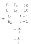
Q2: The charge flowing through a resistance R varies with time t as Q = at - bt2, where a and b are positive constants. The total heat produced in R is :.
(a) a3R/b
(b) a3R/6b
(c) a3R/3b
(d) a3R/2b
View Answer Ans: (b)
Solution:
Given,
Charge, Q = at - bt2 ... (i)
We know that,
Current, I = dθ/dt
So, equation (i) can be written as,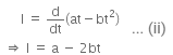
For maximum value of t, the current is given by,
a-2bt = 0
Therefore, t = a/2b ..(iii)
Total heat produced (H) can be given as,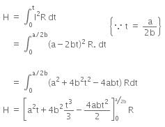
On solving the above equation, we get
Given,
Charge, Q = at - bt2 ... (i)
We know that,
Current, I = dθ/dt
So, equation (i) can be written as,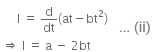
For maximum value of t, the current is given by,
a-2bt = 0
Total heat produced (H) can be given as,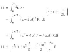
On solving the above equation, we get
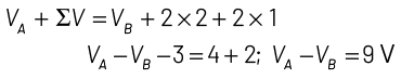
Q3: The potential difference (VA - VB )between the points A and B in the given figure is
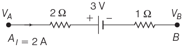
(a) –3 V
(b) +3 V
(c) +6 V
(d) +9 V
View Answer Ans:(d)
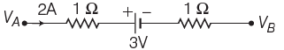
Applying KVL,
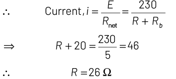
Q4: A filament bulb (500 W, 100 V) is to be used in a 230 V main supply. When a resistance R is connected in series, it works perfectly and the bulb consumes 500 W. The value of R is
(a) 230 Ω
(b) 46 Ω
(c) 26 Ω
(d) 13 Ω
View Answer Ans:(c)
If a rated voltage and power are given, then 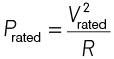
∴ Current in the bulb, i = P/V (∵ P = Vi)
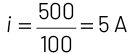
∴ Resistance of bulb,
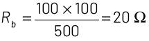
∴ Resistance R is connected in series.
2015
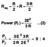
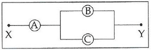
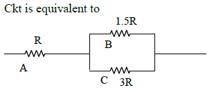
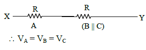
Q1: A, B, and C are voltmeters of resistance R, 1.5 R and 3R respectively as shown in the figure. When some potential difference is applied between X and Y, the voltmeter readings are VA, VB and VC respectively.
Then :
(a)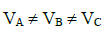
(b)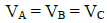
(c)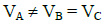
(d)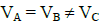
View Answer Solution:
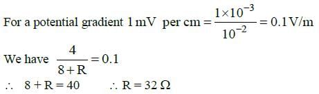
(a) 48 Ω
(b) 32 Ω
(c) 40 Ω
(d) 44 Ω
View Answer Solution:
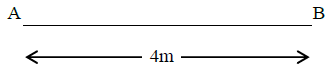
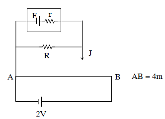
Figure alongside shows a potentiometer wire of length L = 4m and resistance RAB = 8Ω. Resistance connected in series is R.
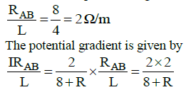
When an accumulator of emf ε = 2V is used, we have current I given by,
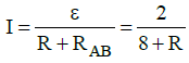
The resistance per unit length of the potentiometer wire is given by,
Q3: Across a metallic conductor of non-uniform cross-section, a constant potential difference is applied. The quantity which remains constant along the conductor is :
(a) electric filed
(b) current density
(c) Current
(d) drift velocity
View Answer Ans: (c)
Solution:
As the cross-sectional area of the conductor is non-uniform so current density will be different.
As, I = JA
It is clear from Eq. (i) that when an area increases the current density decreases so the number of the flow of electrons will be same and thus the current will be constant.
(a) 
(b) 
(c) 
(d) 
View Answer Net resistance of a metal wire having resistivity ρ, we have
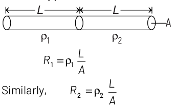
Then, net effective resistance of two metal wires,
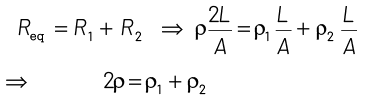
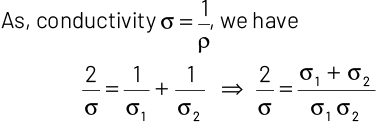
⇒ Net effective conductivity of combined wires,
(a) 0.5 A
(b) 0.25 A
(c) 2 A
(d) 1 A
View Answer Effective resistance of a circuit,
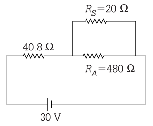
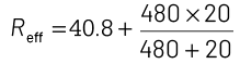
= 40.8 + 19.2 = 60 Ω
So, current flowing across ammeter,
Hence, reading of ammeter = 0.5 A
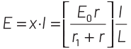
The e.m.f. E will be given by

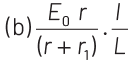

View Answer Ans: (b)
Consider a potentiometer wire of length L and a resistance r are connected in series with a battery of emf E0 and a resistance r1 as shown in figure. Current in wire 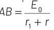
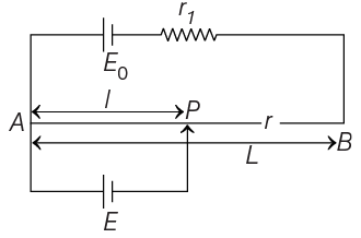
Potential gradient,
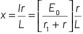
emf produced across E will be given by
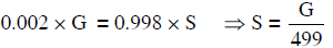
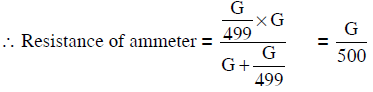
Q1: In an ammeter, 0.2% of the main current passes through the galvanometer. If the resistance of the galvanometer is G, the resistance of the ammeter will be:
(a) 1/500 G
(b) 500/499 G
(c) 1/499 G
(d) 499/500 G
View Answer Ans: (a)
Solution:
Let the shunt resistance be S.
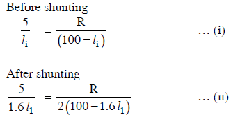
Q2: The resistance in the two arms of the meter bridge is 5 Ω and R Ω, respectively. When the resistance R is shunted with an equal resistance, the new balance point is at 1.6ℓ1. The resistance ‘R’ is :
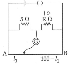
(a) 20 Ω
(b) 25 Ω
(c) 10 Ω
(d) 15 Ω
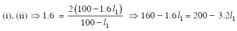
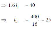
View Answer Ans: (b)
Solution:
Q3: Two cities are 150 km apart. Electric power is sent from one city to another city through copper wires. The fall of potential per km is 8 volts and the average resistance per km is 0.5 Ω. The power loss in the wire is :
(a) 19.2 J
(b) 12.2 kW
(c) 19.2 W
(d) 19.2 kW
View Answer Ans: (d)
Solution:
Total voltage drop across wire = 150 x 8
= 1200 volt
Total resistance of wire
= 150 x 0.5 = 75 Ω
∴ current through wire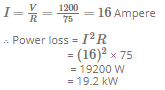
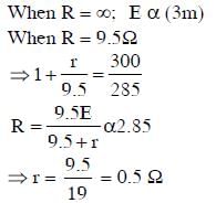
Q4: A potentiometer circuit has been set up for finding the internal resistance of a given cell. The main battery, used across the potentiometer wire, has an EMF of 2.0 V and a negligible internal resistance. The potentiometer wire itself is 4 m long. When the resistance, R connected across the given cell, has a value of:
(i) infinity
(ii) 9.5 Ω, the ‘balancing lengths’, on the potentiometer wire are found to be 3m and 2.85m, respectively.
The value of internal resistance of the cell is:
(a) 0.5 Ω
(b) 0.75 Ω
(c) 0.25 Ω
(d) 0.95 Ω
View Answer Solution:
|
74 videos|314 docs|88 tests
|
FAQs on NEET Previous Year Questions (2014-2025): Current Electricity - Physics Class 12
| 1. What is the formula for calculating the equivalent resistance in a series circuit? |  |
| 2. How do you calculate the total current flowing in a parallel circuit? | |
| 3. What is Ohm's Law and how is it applied in current electricity problems? | |
| 4. What are the main differences between series and parallel circuits? | |
| 5. How can the concept of potential difference be explained in the context of current electricity? | |


Viva Questions
,video lectures
,Important questions
,practice quizzes
,Sample Paper
,study material
,NEET Previous Year Questions (2014-2025): Current Electricity | Physics Class 12
,ppt
,shortcuts and tricks
,Extra Questions
,NEET Previous Year Questions (2014-2025): Current Electricity | Physics Class 12
,Objective type Questions
,Free
,MCQs
,Semester Notes
,Exam
,past year papers
,mock tests for examination
,Summary
,NEET Previous Year Questions (2014-2025): Current Electricity | Physics Class 12
,Previous Year Questions with Solutions
;


NEET Previous Year Questions (2014-2025): Current Electricity Free PDF Download
Importance of NEET Previous Year Questions (2014-2025): Current Electricity
NEET Previous Year Questions (2014-2025): Current Electricity Notes
NEET Previous Year Questions (2014-2025): Current Electricity NEET
Study NEET Previous Year Questions (2014-2025): Current Electricity on the App
|
© EduRev
|
Education Revolution
|


|


