Q41: A single-phase, 230 V, 50 Hz ac mains fed step down transformer (4 : 1) is supplying power to a half-wave uncontrolled ac-dc converter used for charging a battery(12 V dc) with the series current limiting resistor being 19.04 Ω. The charging current is (2007)
(a) 2.43 A
(b) 1.65 A
(c) 1.22 A
(d) 1.0 A
Ans: (d)
Sol:  Input to the converter,
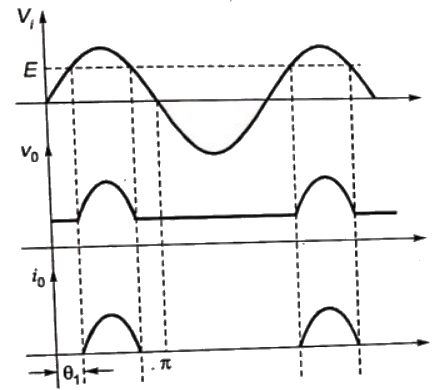
 Diode conducts when Vs ≥ E
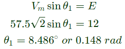
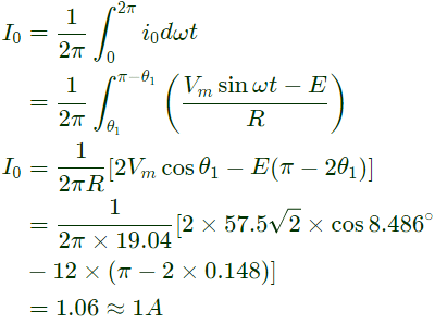
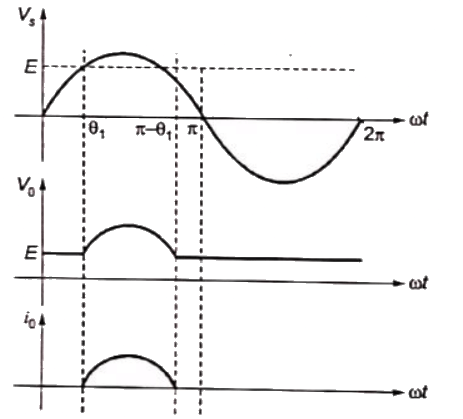 Charging current flows during θ1 ≤ ωt ≤ π − θ1 and can be expressed as,
Q42: A single phase full-wave half-controlled bridge converter feeds an inductive load. The two SCRs in the converter are connected to a common DC bus. The converter has to have a freewheeling diode. (2007)
(a) because the converter inherently does not provide for free-wheeling
(b) because the converter does not provide for free-wheeling for high values of triggering angles
(c) or else the free-wheeling action of the converter will cause shorting of the AC supply
(d) or else if a gate pulse to one of the SCRs is missed, it will subsequently cause a high load current in the other SCR.
Ans: (c)
Sol: 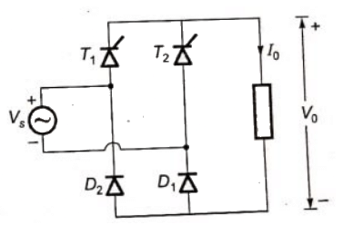 1 − ϕ full wave half controlled bridge converter without free wheeling diode is shown in the figure.
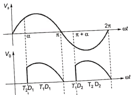 At ωt = α, T1 is fired and T1 starts conducting load current flows through T1D1 for α < ωt < π.
At ωt = π, Vs becomes negative and At D1 gets reverse biased and D2 is forward biased. So during π < ωt < π + α, free wheeling action takes place through T1 and D2 and output voltage becomes zeros.
At ωt = π + α, Load T2 is triggered and load current is transferred from T1 to T2. So, during π + α < ωt < 2π, T2D2 conducts.
At ωt = π + α, It may be possible that load current is not transferred completely from T1 to T2, and T1 and T2 may be conducting simultaneously which results in short circuit of the supply for short direction.
Q43: A three-phase, fully controlled thyristor bridge converter is used as line commutated inverter to feed 50 kW power 420 V dc to a three-phase, 415 V(line), 50 Hz ac mains. Consider dc link current to be constant. The rms current of the thyristor is (2007)
(a) 119.05 A
(b) 79.37 A
(c) 68.73 A
(d) 39.68 A
Ans: (c)
Sol: Let DC link current = Id
DC voltage applied to the inverter
Vd = 420V
Power fed to the inverter
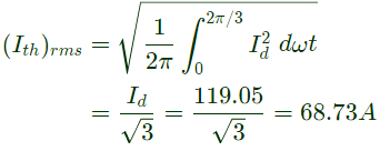
 Current through each thyristor flows for period of 2π/3.
So, rms current of thyristor.
Q44: A single-phase fully controlled thyristor bridge ac-dc converter is operating at a firing angle of 25° and an overlap angle of 10° with constant dc output current of 20 A. The fundamental power factor (displacement factor) at input ac mains is (2007)
(a) 0.78
(b) 0.827
(c) 0.866
(d) 0.9
Ans: (c)
Sol: 

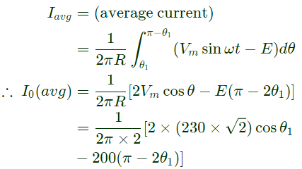
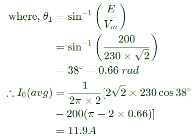
Q45: A single-phase bridge converter is used to charge a battery of 200 V having an internal resistance of 0.2 Ω as shown in figure. The SCRs are triggered by a constant dc signal. If SCR2 gets open circuited, what will be the average charging current ? (2006)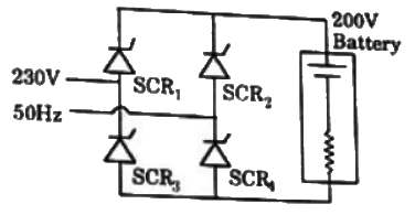 (a) 23.8 A
(b) 15 A
(c) 11.9 A
(d) 3.54 A
Ans: (c)
Sol: T1 and T4 gets forward biased, when
Vm sinθ1 ≤ E
Q46: A 3-phase fully controlled bridge converter with free wheeling diode is fed from 400 V, 50 Hz AC source and is operating at a firing angle of 60°. The load current is assumed constant at 10 A due to high load inductance. The input displacement factor (IDF) and the input power factor (IPF) of the converter will be (2006)
(a) IDF = 0.867; IPF = 0.828
(b) IDF = 0.867; IPF = 0.552
(c) IDF = 0.5; IPF = 0.478
(d) IDF = 0.5; IPF = 0.318
Ans: (c)
Sol: Load current is constant
I0 = 10A
In 3 − ϕ full converter with free wheeling diode, input displacement factor (IDF) = cosα = cos60° = 0.5
RMS value of source current
 RMS value of nth harmonic
 RMS value of fundamental current
 Current distortion factor (CDF)
 Input power factor (IPF) = CDF × IDF = 0.955 × 0.5 ≈ 0.478
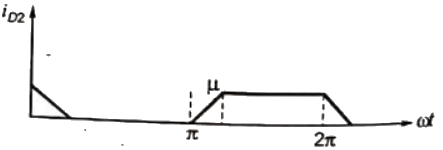
Q47: A single-phase half wave uncontrolled converter circuit is shown in figure. A 2-winding transformer is used at the input for isolation. Assuming the load current to be constant and V = Vmsin ωt, the current waveform through diode D2 will be (2006)
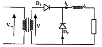 (a)
(a)  (b)
(b)  (c)
(c)  (d)
(d)  Ans: (d)
Sol: Without considering source inductance i.e. (Transformer inductance)
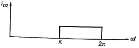 After considering transformer leakage inductance.
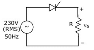
Q48: Consider a phase-controlled converter shown in the figure. The thyristor is fired at an angle α in every positive half cycle of the input voltage. If the peak value of the instantaneous output voltage equals 230 V, the firing angle α is close to (2005)
 (a) 45°
(b) 135°
(c) 90°
(d) 83.6°
Ans: (b)
Sol: 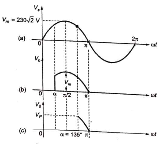 Supply voltage waveform is shown in figure (a). It has peak value of
  If the thyristor is triggered at diring angle α < (π/2), output voltage will also have peak value of 230√2 V
The supply voltage at α = 135°
 So, when thyristor is triggered at α = 135°
230 V will appear across the load, it is also the peak value of the output voltage.
Q49: A three-phase diode bridge rectifier is fed from a 400 V RMS, 50 Hz, threephase AC source. If the load is purely resistive, then peak instantaneous output voltage is equal to (2005)
(a) 400 V
(b) 400√2 V
(c) 400(√2/3) V
(d) 400/√3 V
Ans: (b)
Sol: Maximum value of inout voltage V − m = 400√2 V
Since load is purely resistive, therefore peak instantaneous output voltage V−m = 400√2 V
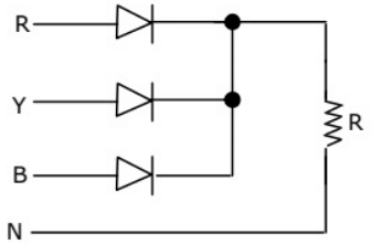
Q50: The circuit in figure shows a 3-phase half-wave rectifier. The source is a symmetrical, 3-phase four-wire system. The line-to-line voltage of the source is 100 V. The supply frequency is 400 Hz. The ripple frequency at the output is (2004)
 (a) 400 Hz
(b) 800 Hz
(c) 1200 Hz
(d) 2400 Hz
Ans: (c)
Sol: By drawing the output voltage.
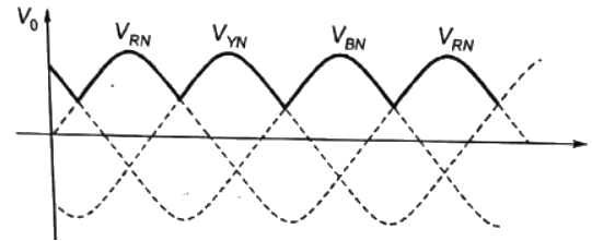 Each diode conducted for 120° only.
there are three pulses of output voltage during one cycle of inout voltage.
So, frequency of ripple = 3f =3 x 400 = 1200 Hz
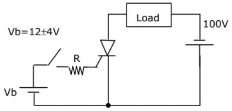
Q51: The triggering circuit of a thyristor is shown in figure. The thyristor requires a gate current of 10 mA, for guaranteed turn-on. The value of R required for the thyristor to turn on reliably under all conditions of Vb variation is (2004)
 (a) 10000Ω
(b) 1600Ω
(c) 1200Ω
(d) 800Ω
Ans: (d)
Sol:  The thyristor must turn on even for minimum value of Vb.
Gate current for gauranteed turn-on = Ib = 10mA, neglecting voltage between gate and cathode. Therefore, required value of R = 
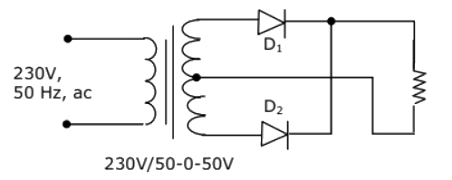
Q52: The circuit in figure shows a full-wave rectifier. The input voltage is 230 V (rms) single-phase ac. The peak reverse voltage across the diodes D1 and D2 is (2004)
 (a) 100√2 V
(b) 100 V
(c) 50√2 V
(d) 50 V
Ans: (a)
Sol: 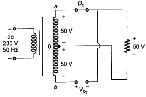 When 'a' is positive with resoect to 'b' diode D1 conducts and diode D2 is reverse baised.
Applying KVL, VD2 = 100V (rms)
So, diode D2 is subjected to reverse voltage of 100 V (rms). Similarly, during negative half cycle, D1 is subjected to reverse voltage of 100 V (rms). Thus, for diode D1 and D2 peak reverse voltage is 100√2V (maximum value of the voltage across the diodes.)
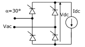
Q53: A phase-controlled half-controlled single-phase converter is shown in figure. The control angle α = 30°. The output dc voltage wave shape will be a s shown in (2003)
 (a)
(a) 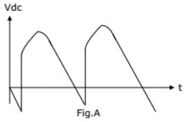 (b)
(b) 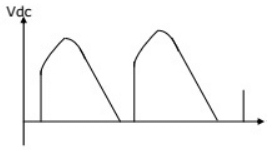 (c)
(c) 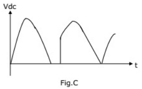 (d)
(d) 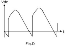 Ans: (b)
Sol: Due to free wheeling action, negative voltage is eliminated and power factor is improved in single-phase half controlled rectifier.
Q54: A fully controlled natural commutated 3-phase bridge rectifier is operating with a firing angle α = 30°, The peak to peak voltage ripple expressed as a ratio of the peak output dc voltage at the output of the converter bridge is (2003)
(a) 0.5
(b) √3/2
(c) (1 - √3/2)
(d) (√3 - 1)
Ans: (a)
Sol: 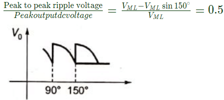
Q55: In the single phase diode bridge rectifier shown in figure, the load resistor is R = 50 Ω. The source voltage is V = 200 sinωt, where ω = 2π × 50 radians per second. The power dissipated in the load resistor R is (2002)
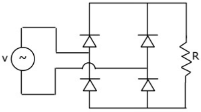 (a) (3200/π) W
(b) (400/π) W
(c) 400 W
(d) 800 W
Ans: (c)
Sol: 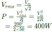
Q56: A three phase thyristor bridge rectifier is used in a HVDC link. The firing angle a (as measured from the point of natural commutation) is constrained to lie between 5° and 30°. If the dc side current and ac side voltage magnitudes are constant, which of the following statements is true (neglect harmonics in the ac side currents and commutation overlap in your analysis) (2002)
(a) Reactive power absorbed by the rectifier is maximum when α = 5°
(b) Reactive power absorbed by the rectifier is maximum when α = 30°
(c) Reactive power absorbed by the rectifier is maximum when α = 15°
(d) Reactive power absorbed by the rectifier is maximum when α = 10°
Ans: (b)
Q57: A six pulse thyristor rectifier bridge is connected to a balanced 50 Hz three phase ac source. Assuming that the dc output current of the rectifier is constant, the lowest frequency harmonic component in the ac source line current is (2002)
(a) 100 Hz
(b) 150 Hz
(c) 250 Hz
(d) 300 Hz
Ans: (c)
Sol: 
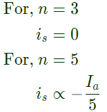 Lowest harmonic present is fifth harmonic. Its frequency = 50 x 5 = 250 Hz.
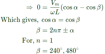
Q58: A half-wave thyristor converter supplies a purely inductive load, as shown in figure. If the triggering angle of the thyristor is 120°, the extinction angle will be (2001)
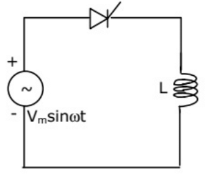 (a) 240°
(b) 180°
(c) 200°
(d) 120°
Ans: (a)
Sol: 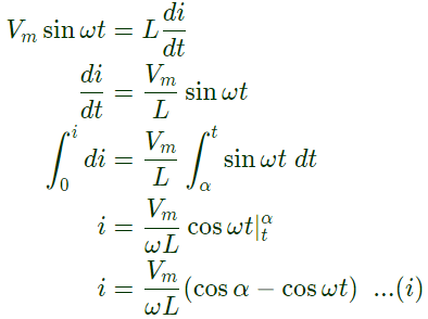

Q59: AC-to-DC circulating current dual converters are operated with the following relationship between their triggering angles (α1 and α2). (2001)
(a) α1 + α2 = 180°
(b) α1 + α2 = 360°
(c) α1 − α2 = 180°
(d) α1 + α2 = 90°
Ans: (a)
 Input to the converter,
 Diode conducts when Vs ≥ E
 Charging current flows during θ1 ≤ ωt ≤ π − θ1 and can be expressed as,
 1 − ϕ full wave half controlled bridge converter without free wheeling diode is shown in the figure.
 At ωt = α, T1 is fired and T1 starts conducting load current flows through T1D1 for α < ωt < π.
 Current through each thyristor flows for period of 2π/3.


 (a) 23.8 A


 RMS value of nth harmonic
 RMS value of fundamental current
 Current distortion factor (CDF)
 Input power factor (IPF) = CDF × IDF = 0.955 × 0.5 ≈ 0.478
  (a)
(a)  (b)
(b)  (c)
(c)  (d)
(d)  Ans: (d)
 After considering transformer leakage inductance.
 (a) 45°
 Supply voltage waveform is shown in figure (a). It has peak value of
  If the thyristor is triggered at diring angle α < (π/2), output voltage will also have peak value of 230√2 V
 So, when thyristor is triggered at α = 135°
 (a) 400 Hz
 Each diode conducted for 120° only.
 (a) 10000Ω
 The thyristor must turn on even for minimum value of Vb.
 (a) 100√2 V
 When 'a' is positive with resoect to 'b' diode D1 conducts and diode D2 is reverse baised.
 (a)
(a)  (b)
(b)  (c)
(c)  (d)
(d)  Ans: (b)
 (a) (3200/π) W

 Lowest harmonic present is fifth harmonic. Its frequency = 50 x 5 = 250 Hz.
 (a) 240°


