Progressive Waves & Superposition of Waves | Physics Class 11 - NEET PDF Download

The waves of water or waves on a string travel in a particular direction. But, have you ever imagined how is this direction decided? What is the influence of this movement? In order to understand this concept in-depth, it is important to learn about progressive wave and its displacement aspect.
Progressive Wave
A progressive wave is a term given to a wave that travels from a specific point A in the medium to another point B. In simple terms, a wave that continuously travels in a medium in the same direction minus the changes is known as a traveling wave or progressive wave. Furthermore, a progressive wave is of two types; namely, transverse wave and longitudinal wave.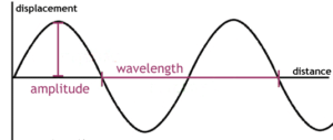
- Transverse Waves: These are waves in which the particle displacement in the medium is measured perpendicular to the wave direction or direction of wave travel.
- Longitudinal Waves: With Longitudinal Waves, the particle displacement remains in the same direction to the wave travel.
Learn more about transverse and longitudinal waves here.
Plane Progressive Harmonic Wave
During the transmission of a wave via a medium, the particles present in the medium tend to vibrate harmonically about their mean positions; in this case, the wave is tagged as a plane progressive harmonic wave.
Simple Harmonic Progressive Wave
This waveform continuously travels in a specific direction without any transition in form. Furthermore, the particles of the medium tend to move harmonically about their mean position carrying the same amplitude and period.
Characteristics of SHM Wave
- Note that, all particles or components of medium exhibit SHM while the wave passes through a medium.
- The same amplitude is maintained by all particles as they vibrate.
- Energy is conducted through the medium.
- The total number of particles vibrate with a similar frequency.
Plane Progressive Harmonic Wave: Displacement Relation
Considering a plane progressive harmonic wave, the displacement of a sinusoidal wave traveling in the x-direction (positive) is mentioned below:
y = a sin(kx – ωt + φ)
Here, ‘a’ denotes the amplitude of the wave, angular wave number is denoted by ‘k’, whereas ‘ω’ is the angular frequency. The phase is mentioned as (kx – ωt + φ), and φ signifies the phase angle or phase constant. Furthermore, the sine function, as well as the time-dependent phase (wave), resemble the oscillation of a string component, whereas the amplitude of wave defines the extremes of the component’s displacement. It is important to remember that, the constant ‘ϕ’ is termed as initial phase angle.
Wavelength of Progressive Wave
The wavelength ‘λ’ for a progressive wave is basically the distance measured between two succeeding points of the same phase at a particular time. Considering a stationary wave, this is twice the distance measured between two successive nodes or antinodes. The propagation constant is defined as ‘k’. The SI unit is calculated in radian per meter or rad m-1.
k=2π/λ
Frequency and Period of Progressive Wave
The time period ‘T’ of wave oscillation is the duration taken by any component of the medium takes to travel over one complete oscillation. This is related to ‘ω’ or angular frequency through the following relation:
ω = 2π/T
In this, wave frequency ‘v’ is mentioned as 1/T and is also related to angular frequency as:
v = ω/2π
It can also be defined as the number of oscillations/unit time prepared in a string element while the wave passes through it. This is usually calculated in Hertz.
Superposition of Waves
- Definition: The principle of superposition of waves is based on the superposition theorem. It states that the net displacement of any component on a medium, such as a string, at a given time is the sum of the displacements caused by each individual wave acting on that component.
- Explanation with Example: Imagine a string wave where multiple waves overlap. According to the principle of superposition, the resulting wave is the algebraic sum of the individual waveforms. This means that overlapping waves, with frequencies f1, f2, ..., fn, do not interfere with each other’s motion. For instance, if two waves with different amplitudes and frequencies overlap on a string, the resulting wave will be the sum of the individual waves.
- Application of Principle: The principle of superposition affirms that overlapping waves combine to form a resultant wave. This concept is crucial in understanding how waves interact and propagate through a medium without hindering each other's motion. The wave function, denoted as 'y,' represents the disturbance in the medium caused by the overlapping waves. It mathematically expresses how the waves add up to create the resultant wave.
In mathematical terms, the superposition principle can be described as given below. Let's say y1(x, t) and y2(x, t) is the displacements produced by two waves in the medium. Let P be the point where these two ways come and meet. Now using the principle of superposition to find the resultant displacement (y).
Y = y1(x, t) + y2(x, t)
If two or more waves are travelling and meeting at one point in a medium and the wave functions for the individual waves are given by,
Y = f1(x - Vt)
Y = f2(x - Vt)
Y = fn(x - Vt)
The resultant wave after displacement is given by,

|
95 videos|367 docs|98 tests
|
FAQs on Progressive Waves & Superposition of Waves - Physics Class 11 - NEET
| 1. What is the principle of superposition? |  |
| 2. How does interference occur? | |
| 3. What is the difference between constructive and destructive interference? | |
| 4. Can waves interfere with each other even if they have different frequencies? | |
| 5. How can interference be used in practical applications? | |


Summary
,shortcuts and tricks
,Extra Questions
,Sample Paper
,Exam
,Important questions
,video lectures
,past year papers
,Progressive Waves & Superposition of Waves | Physics Class 11 - NEET
,MCQs
,Semester Notes
,Free
,ppt
,Progressive Waves & Superposition of Waves | Physics Class 11 - NEET
,study material
,mock tests for examination
,Previous Year Questions with Solutions
,Progressive Waves & Superposition of Waves | Physics Class 11 - NEET
,practice quizzes
,Objective type Questions
,Viva Questions
;


Progressive Waves & Superposition of Waves Free PDF Download
Importance of Progressive Waves & Superposition of Waves
Progressive Waves & Superposition of Waves Notes
Progressive Waves & Superposition of Waves NEET Questions
Study Progressive Waves & Superposition of Waves on the App
|
© EduRev
|
Education Revolution
|


|


