Resonance in LCR Circuit | Physics Class 12 - NEET PDF Download
| Table of contents |
|
| Resonance in LCR Circuit |
|
| Sharpness of Resonance (Q - factor) |
|
| Choke Coil |
|
| Oscillations in LC Circuits |
|

Intelligence agencies and police officers are capable of tapping the communication and activities of anti-social elements. Have you ever wondered how is it done? It is done through the concept of 'resonance'. The idea of resonance is also used in TV channels for clarity: a particular frequency is assigned to a channel and when this frequency is received by the receiver, the current corresponding to this frequency becomes maximum. This helps in the maximum possible separation of channels, thus increasing their clarity.
In this document, we will study the resonance conditions of LCR circuits.
Resonance in LCR Circuit
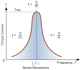
A series LCR circuit is said to be in the resonance condition when the current through it has its maximum value.
The current amplitude I0 for a series LCR circuit is given by
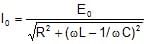
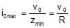
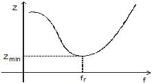
I0 becomes zero both for ω → 0 and ω → ∞. The value of I0 is the maximum when
 or
or  ⇒
⇒
Then impedance will be the minimum
Zmin = R
The circuit is purely resistive. The current and voltage are in the same phase and the current in the circuit is maximum. This condition of the LCR circuit is called the resonance condition.
 Resonance in LCR Circuit
The variance of I0 v/s ω shown in the following figure
So cosϕ=  =
=  = 1
= 1
V = V0 sin (ωt)
The impedance phase of the resonance circuit,
Impedance of the circuit is minimum and heat generated in the circuit is maximum.
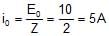
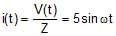
Q1. In the following LCR circuit find Z, i(t), VOC, and VOL at the resonance frequency
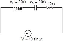
Solution:
Z = Zmin = R = 2?
VO L = i0XC = 100 volt
VO L = i0 XL = 100 volt
Note:
The above circuit is used as a voltage amplifier (magnification) as the peak value of voltage by the source is only 10 while we can have maximum voltage up to 100 (VO C& VO L)
Q2. A series LCR with R = 20 ?, L = 1.5 H, and C = 35 μF is connected to a variable frequency 200 V a.c. supply. When the frequency of the supply equals the natural frequency of the circuit. What is the average power transferred to the circuit in one complete cycle?
Solution:
When the frequency of the supply equals the natural frequency of the circuit, resonance occurs.
Therefore, Z = R = 20 ohm
irms = 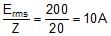
Average power transferred/cycle
P = Ermsirms cos0° = 200 × 10 × 1 = 2000 watt
Sharpness of Resonance (Q - factor)
The Q-factor of a series resonant circuit is defined as the ratio of the resonant frequency to the difference in two frequencies taken on both sides of the resonant frequency such that at each frequency, the current amplitude becomes  times the value of the resonant frequency.
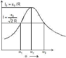
Mathematically Q-factor:
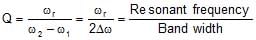
or 
Choke Coil
A choke coil is simply an inductor with large inductance which is used to reduce current in a.c. circuit without much loss of energy.
Principle: A choke coil is based upon the principle that when a.c. flows through an inductor, the current lags behind the e.m.f. by a phase angle π/2.
Construction: A choke coil is an inductance. It consists of a large number of turns of insulated copper wire wound over a soft iron core. To minimize loss of electrical energy due to the production of eddy currents, a laminated iron core is used.
In practice, a low-frequency choke coil is made of insulated copper wire wound on a soft iron core, while a high-frequency choke coil has air as core materials
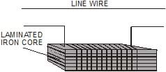
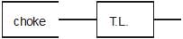
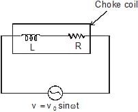
Working: As shown in the figure, a choke is put in series across an electrical appliance of resistance R and is connected to an a.c. source.
The average power dissipated per cycle in the circuit is
Pav = Veff Ieff cosϕ = Veff Ieff  .
.
Inductance L of the choke coil is very large so that R << wL. Then
Power factor cosϕ ≌ 
 0
0 
tanϕ = 
Uses: In a.c. circuit, a choke coil is used to control the current in place of a resistance. If a resistance is used to control the current, the electrical energy will be wasted in the form of heat. A choke coil decreases the current without wasting electrical energy in the form of heat.
Oscillations in LC Circuits
If a charged capacitor C is short-circuited through an inductor L, the charge and current in the circuit start oscillating simply harmonically. If the resistance of the circuit is zero, no energy is dissipated as heat. Assume an ideal situation in which energy is not radiated away from the circuit. With these idealizations resistance and no radiation, the oscillations in the circuit persist indefinitely and the energy is transferred from the capacitor's electric field to the inductor's magnetic field back and forth. The total energy associated with the circuit is constant. This is analogous to the transfer of energy in an oscillating mechanical system from potential energy to kinetic energy and back, with constant total energy. Such an analogous mechanical system is an example of spring-mass system.
Let us now derive an equation for the oscillations of charge and current in an L-C circuit.
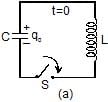
Refer to figure (a): The capacitor is charged to a potential difference V such that charge on capacitor q0 = CV
Here q0 is the maximum charge on the capacitor. At time t = 0, it is connected to an inductor through a switch S. At time t = 0, the switch S is closed.
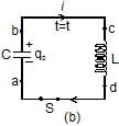
Refer to figure (b): When the switch is closed, the capacitor starts discharging. Let at time t charge on the capacitor is q (<q0) and since, it is further decreasing, there is a current i in the circuit in the direction shown in the figure.
The potential difference across capacitor = potential difference across inductor, or
Vb - Va = Vc - Vd
Therefore,  Now, as the charge is decreasing, i =
or  = -
= - 
Substituting in equation (1), we get

or  = -
= - 
This is the standard equation of simple harmonic motion 
Here w = 
The general solution of equation, is
q = q0 cos (ωt ± ϕ)
In our case ϕ = 0 as q = q0 at t = 0.
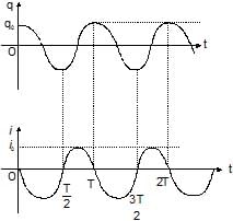
Thus, we can say that the charge in the circuit oscillates with angular frequency ω given by equation (3). Thus,
ln L-C oscillations, q, i and  all oscillate simply harmonically with the same angular frequency ω, but the phase difference between q and i or between i and
  is that their amplitudes are q0 q0ω is ω2 q0 respectively. So,
q = q0 cosωt
i = - = q0ω sin ωt
and  cosωt
cosωt
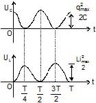
Potential energy in the capacitor
UC =  =
= 
The potential energy in the inductor
UL =  =
= 
Thus potential energy stored in the capacitor and that in the inductor also oscillates between maximum value and zero with double the frequency. All these quantities are shown in the figures that follow
Q3. A capacitor of capacitance 25 μF is charged to 300 V. It is then connected across a 10 μH inductor. The resistance of the circuit is negligible.
(a) Find the frequency of oscillation of the circuit.
(b) Find the potential difference across the capacitor and magnitude of circuit current 1.2 ms after the inductor and capacitor are connected.
(c) Find the magnetic energy and electric energy at t = 0 and t = 1.2 ms.
Solution:
(a) The frequency of oscillation of the circuit is,
f = 
Substituting the given values we have,  =
= 
(b) Charge across the capacitor at time t will be,
q = q0 cos ωt
and i = - q0 ωsin ωt
Here q0 = CV0 = (25 × 10-6) (300) = 7.5 × 10⁻³ C
Now, charge is the capacitor after t = 1.2 × 10⁻³ s is,
q = (7.5 × 10⁻³) cos (2p × 318.3) (1.2 × 10⁻³)C
= 5.53 × 10⁻³C
Therefore, P.D. across capacitors,
V = 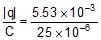 = 221.2 volt
The magnitude of current in the circuit at
t = 1.2 × 10⁻³ s is,
|i| = q0 ω sinωt
= (7.5 × 10⁻³) (2p) (318.3) sin(2p × 318.3) (1.2 × 10⁻³) A = 10.13 A
(c) At t = 0: The current in the circuit is zero. Hence,UL = 0
Charge on the capacitor is the maximum.
Hence, Uc = 
or Uc = 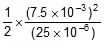 = 1.125 J
Therefore, Total energy E = UL + UC = 1.125 J
At t = 1.2 ms
UL =  =
=  (10.13)2 = 0.513 J
UC = E - UL = 1.125 - 0.513 = 0.612 J
Otherwise, UC can be calculated as,
UC =  =
= 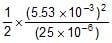 = 0.612 J
|
74 videos|314 docs|88 tests
|
FAQs on Resonance in LCR Circuit - Physics Class 12 - NEET
| 1. What is resonance in an LCR circuit? |  |
| 2. How does resonance affect the sharpness of a circuit's response? | |
| 3. What is the role of a choke coil in an LCR circuit? | |
| 4. How do oscillations occur in LC circuits? | |
| 5. What are some applications of resonance in LCR circuits? | |


Viva Questions
,mock tests for examination
,Resonance in LCR Circuit | Physics Class 12 - NEET
,Objective type Questions
,Important questions
,Resonance in LCR Circuit | Physics Class 12 - NEET
,Exam
,ppt
,video lectures
,Extra Questions
,Summary
,Semester Notes
,Sample Paper
,practice quizzes
,Previous Year Questions with Solutions
,past year papers
,Free
,MCQs
,Resonance in LCR Circuit | Physics Class 12 - NEET
,study material
,shortcuts and tricks
;


Resonance in LCR Circuit Free PDF Download
Importance of Resonance in LCR Circuit
Resonance in LCR Circuit Notes
Resonance in LCR Circuit NEET Questions
Study Resonance in LCR Circuit on the App
|
© EduRev
|
Education Revolution
|


|


within 7 days!