Class 10 Exam > Class 10 Notes > Physics Class 10 ICSE > Revision Notes: Current Electricity
Revision Notes: Current Electricity | Physics Class 10 ICSE PDF Download

Current
- Current is the rate of flow of charge across a cross-section normal to the direction of flow of current.
Current I = Charge (Q)/Time (t) - It is a scalar quantity. Its SI unit is ampere (A).
- Current is one ampere if the rate of flow of charge is one coulomb per second.
- If n electrons pass through the cross-section of a conductor in time t, then the total charge passed through the conductor is given as Q = ne, and current in the conductor is given as
I = Q/t = ne/t
Concept of Potential and Potential Difference
- The conductor with higher concentration of electrons is said to be at a lower potential, and the conductor with lower concentration of electrons is said to be at a higher potential.
- The electrons flow from a body at a lower potential to a body at a higher potential.
- Potential is the electrical state of a conductor which determines the direction of flow of charge when the two conductors are either kept in contact or joined by a metallic wire.
- The electric current flows from a body at a higher potential to a body at a lower potential, and this is called conventional current. This direction is opposite to the direction of flow of electrons which is called electronic current.
Measurement of Potential as Work Done Per Unit Charge
- The potential at a point is defined as the work done in bringing a unit positive charge from infinity to that point.
Potential difference = Work done/Charge
V = W/Q - The potential difference between two points is said to be 1 volt if the work done in bringing 1 coulomb of charge from infinity to the point is 1 joule.
- The potential difference between two points is equal to the work done in moving a unit positive charge from one point to the other.
VA - VB = W/Q - It is a scalar quantity. Its SI unit is also volt (V).
Concept of Resistance
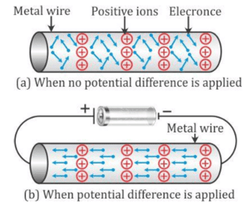
- There is always some obstruction in the current which flows through a conductor like a metal wire, and this obstruction is called its electrical resistance.
- The current in the circuit flows due to the drift of electrons. The metal wire has free electrons which move in a random manner.
- When the ends of a wire are connected to a cell, the electrons start moving from the negative terminal to the positive terminal. In this process, they collide with the positive ions, and due to this, the speed of electrons decreases. Thus, the metal offers resistance to the flow of electrons because of these collisions.
The resistance of a conductor depends on four factors:
- Length of the conductor:
Resistance (R) ∝ length (l) - Thickness of the conductor:
Resistance (R) ∝ 1/Area of cross-section(A) - Nature of the conductor: The resistance depends on the material of the wire as there is different concentration and different arrangement of atoms in different materials.
- Temperature of the wire: A higher temperature of the wire causes the ions in it to vibrate more rapidly. As a result, the number of collisions increases, and hence, the resistance increases.
Ohm’s Law
- Ohm’s law: The current flowing through a conductor is directly proportional to the potential difference V across its ends provided the temperature and physical conditions of the conductor remain the same.
I ∝ V
V = IR - R is constant for a given metallic wire at a given temperature, and this constant is named as resistance.
- Its SI unit is ohm and is denoted as Ω.
- If we plot the I–V graph for a conductor, then it shows a linear nature.
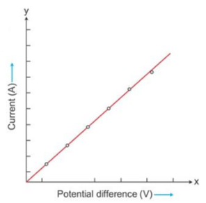
- The slope of the graph is the reciprocal of the resistance of the conductor.
Slope = ΔI/ΔV = 1/Resistance of conductor - Conductance: It is defined as the reciprocal of resistance.
Conductance = 1/Resistance - Hence, the slope of the I–V graph gives the conductance of the conductor.
Ohmic and Non-ohmic Resistors
- Ohmic resistors: The conductors which obey Ohm's law are called ohmic resistors or linear resistances.
For such resistors, a graph plotted for the potential difference V against the current I is a straight line, and the value of resistance R is the same irrespective of the value of V or I. - Non-ohmic resistors: The conductors which do not obey Ohm's law are called non-ohmic resistors or non-linear resistances.
For these devices, the graph plotted for the potential difference V against the current I is not a straight line, but it is a curve.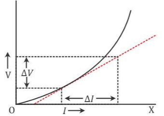
- Superconductors: A superconductor is a substance of zero resistance (or infinite conductance) at a very low temperature.
The superconductors can be very useful provided it is possible to obtain them at room temperature.
The size of computers could then be reduced to a few centimetres and power lines could then be made as thin as a single cable.
Specific Resistance or Resistivity
- The resistance of a wire depends on the following factors:
i. Directly proportional to the length (l) of the wire
ii. Inversely proportional to the area of cross-section of the wire
iii. Nature of the material of the wire
- Here, ρ is the constant of proportionality and is called the electrical resistivity or specific resistance of the material of the wire.
- The resistivity will be given as
ρ = RA/l - Resistivity is the resistance of a wire of that material of unit length and unit area of cross-section.
- Its SI unit is ohm-metre (Ω m).
- Conductivity: The reciprocal of resistivity is called conductivity. It is represented by σ.

- Its SI unit is ohm−1 metre−1 or siemen metre−1 .
Choice of Material of Wire
The choice of material of a wire depends on the purpose for which the wire is to be used.
- The wires which are used for electrical connections and power transmission should possess negligible resistance.
- The resistance wires (or standard resistors) are made of materials such as nichrome, manganin, constantan etc., for which the resistivity is quite large and the effect of change in temperature on their resistance is negligible.
- A fuse wire is made from an alloy of lead and tin because its resistivity is high and melting point is low.
- A wire made of tungsten is used for the filament of an electric bulb because it has a high melting point and high resistivity.
- A nichrome wire is used as the heating element in appliances such as a heater, toaster and oven, because the resistivity of nichrome is very high and increase in its value with increase in temperature is also high.
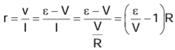
Electromotive Force, Terminal Voltage and Internal Resistance of a Cell
- When no current is drawn from a cell, i.e. when the cell is in open circuit, the potential difference between the terminals of the cell is called its electromotive force (emf).
- The emf of a cell is denoted by the symbol ε (epsilon). Its unit is volt (V).
Factors Affecting the EMF of a Cell
- The emf of a cell is the characteristic of the cell. It is different for different kinds of cells.
- The emf of a cell depends on
- Material of the electrodes
- Electrolyte used in the cell
- It is independent of
- Shape of electrodes
- Distance between the electrodes
- Amount of electrolyte
- The emf of a cell is also defined as the energy spent (or work done) per unit charge in taking a positive charge around the complete circuit of the cell.
ε = W/q0
Terminal Voltage of a Cell
- When current is drawn from a cell, i.e. when the cell is in a closed circuit, the potential difference between the electrodes of the cell is called its terminal voltage.
- The terminal voltage of a cell is denoted by the letter V. It is also expressed in volt (V).
- The terminal voltage of a cell is defined as the work done per unit charge in carrying a positive charge around the circuit connected across the terminals of the cell.
V = W'/q0 - The terminal voltage V of a cell is less than its emf ε by the amount of energy spent in the flow of unit positive charge (taking q0 = 1 C) through the electrolyte inside the cell.
ε = V + v - When a larger current is drawn from the cell, a greater number of charge carriers flows through the electrolyte, and hence, more work is done. This results in more voltage drop v and hence less terminal voltage V.
Internal Resistance of a Cell
- When current is drawn from a cell, it flows from the anode to the cathode in the external circuit and from the cathode to the anode inside the cell through the electrolyte so as to maintain a continuous flow.
- The resistance offered by the electrolyte inside the cell to the flow of current is called the internal resistance of the cell. It is denoted by r. Its unit is ohm Ω.
- When current I is drawn from the cell of which the internal resistance is r, the voltage drop is
v = Ir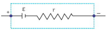
Relationship between the emf, terminal voltage and internal resistance
- Surface area of the electrodes
- Distance between the electrodes
- Nature and concentration of the electrolyte
- Temperature of the electrolyte
Resistors in Series
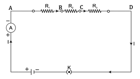
- The current in series remains the same across all the resistors.
- The resultant resistance of the circuit is given as
Rs = R1 + R2 + R3 - Here, Rs is the resultant resistance. The resultant resistance is greater than all the resistances
Resistors in Parallel
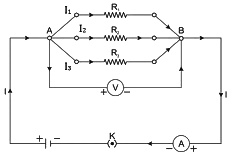
- The potential difference in parallel remains the same across all the resistors.
- The resultant resistance of the circuit is given as
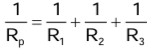
- Here, Rp is the resultant resistance. The resultant resistance is lesser than all the resistances.
The document Revision Notes: Current Electricity | Physics Class 10 ICSE is a part of the Class 10 Course Physics Class 10 ICSE.
All you need of Class 10 at this link: Class 10
|
28 videos|121 docs|14 tests
|
FAQs on Revision Notes: Current Electricity - Physics Class 10 ICSE
| 1. What is the difference between potential and potential difference in electric circuits? |  |
Ans.Potential refers to the amount of electric potential energy per unit charge at a specific point in an electric field, while potential difference (also known as voltage) is the difference in electric potential between two points in a circuit. It represents the work done in moving a unit charge from one point to another and is measured in volts (V).
| 2. How does resistance affect the flow of current in a circuit? | |
Ans.Resistance is a measure of how much a material opposes the flow of electric current. According to Ohm's Law, the current (I) flowing through a conductor between two points is directly proportional to the voltage (V) across the two points and inversely proportional to the resistance (R) of the conductor. Higher resistance results in lower current flow for a given voltage.
| 3. What is Ohm's Law and how is it applied in electrical circuits? | |
Ans.Ohm's Law states that the current flowing through a conductor between two points is directly proportional to the voltage across the two points and inversely proportional to the resistance. It is mathematically expressed as V = I × R, where V is voltage, I is current, and R is resistance. This law is fundamental in analyzing and designing electrical circuits.
| 4. What distinguishes ohmic resistors from non-ohmic resistors? | |
Ans.Ohmic resistors obey Ohm's Law, meaning their current-voltage relationship is linear and consistent regardless of the voltage applied. Non-ohmic resistors do not follow this linear relationship; their resistance can change with voltage or current, resulting in a non-linear graph of current versus voltage.
| 5. How do resistors in series and parallel differ in terms of total resistance? | |
Ans.In a series circuit, the total resistance is the sum of the individual resistances (R_total = R1 + R2 + R3 + ...). In contrast, in a parallel circuit, the total resistance is found using the formula 1/R_total = 1/R1 + 1/R2 + 1/R3 + ..., resulting in a total resistance that is less than the smallest individual resistance. This difference affects how current flows through each configuration.
About this Document

4.74/5
Rating

Oct 10, 2025
Last updated
Document Description: Revision Notes: Current Electricity for Class 10 2025 is part of Physics Class 10 ICSE preparation.
The notes and questions for Revision Notes: Current Electricity have been prepared according to the Class 10 exam syllabus. Information about Revision Notes: Current Electricity covers topics
like Current, Concept of Potential and Potential Difference, Concept of Resistance, Ohm’s Law, Ohmic and Non-ohmic Resistors, Specific Resistance or Resistivity, Electromotive Force, Terminal Voltage and Internal Resistance of a Cell, Resistors in Series, Resistors in Parallel and Revision Notes: Current Electricity Example, for Class 10 2025 Exam. Find important definitions, questions, notes, meanings, examples, exercises and tests below for Revision Notes: Current Electricity.
Introduction of Revision Notes: Current Electricity in English is available as part of our Physics Class 10 ICSE
for Class 10 & Revision Notes: Current Electricity in Hindi for Physics Class 10 ICSE course.
Download more important topics related with notes, lectures and mock test series for Class 10
Exam by signing up for free. Class 10: Revision Notes: Current Electricity | Physics Class 10 ICSE
Description
Full syllabus notes, lecture & questions for Revision Notes: Current Electricity | Physics Class 10 ICSE - Class 10 | Plus excerises question with solution to help you revise complete syllabus for Physics Class 10 ICSE | Best notes, free PDF download
Information about Revision Notes: Current Electricity
In this doc you can find the meaning of Revision Notes: Current Electricity defined & explained in the simplest way possible. Besides explaining types of
Revision Notes: Current Electricity theory, EduRev gives you an ample number of questions to practice Revision Notes: Current Electricity tests, examples and also practice Class 10
tests

Related Searches
practice quizzes
,study material
,ppt
,Important questions
,Exam
,Viva Questions
,Summary
,Free
,Semester Notes
,MCQs
,shortcuts and tricks
,Revision Notes: Current Electricity | Physics Class 10 ICSE
,Sample Paper
,Objective type Questions
,Revision Notes: Current Electricity | Physics Class 10 ICSE
,Revision Notes: Current Electricity | Physics Class 10 ICSE
,video lectures
,Previous Year Questions with Solutions
,mock tests for examination
,Extra Questions
,past year papers
,


Additional Information about Revision Notes: Current Electricity for Class 10 Preparation
Revision Notes: Current Electricity Free PDF Download
The Revision Notes: Current Electricity is an invaluable resource that delves deep into the core of the Class 10 exam.
These study notes are curated by experts and cover all the essential topics and concepts, making your preparation more efficient and effective.
With the help of these notes, you can grasp complex subjects quickly, revise important points easily,
and reinforce your understanding of key concepts. The study notes are presented in a concise and easy-to-understand manner,
allowing you to optimize your learning process. Whether you're looking for best-recommended books, sample papers, study material,
or toppers' notes, this PDF has got you covered. Download the Revision Notes: Current Electricity now and kickstart your journey towards success in the Class 10 exam.
Importance of Revision Notes: Current Electricity
The importance of Revision Notes: Current Electricity cannot be overstated, especially for Class 10 aspirants.
This document holds the key to success in the Class 10 exam.
It offers a detailed understanding of the concept, providing invaluable insights into the topic.
By knowing the concepts well in advance, students can plan their preparation effectively.
Utilize this indispensable guide for a well-rounded preparation and achieve your desired results.
Revision Notes: Current Electricity
Revision Notes: Current Electricity Notes offer in-depth insights into the specific topic to help you master it with ease.
This comprehensive document covers all aspects related to Revision Notes: Current Electricity.
It includes detailed information about the exam syllabus, recommended books, and study materials for a well-rounded preparation.
Practice papers and question papers enable you to assess your progress effectively.
Additionally, the paper analysis provides valuable tips for tackling the exam strategically.
Access to Toppers' notes gives you an edge in understanding complex concepts.
Whether you're a beginner or aiming for advanced proficiency, Revision Notes: Current Electricity Notes on EduRev are your ultimate resource for success.
Revision Notes: Current Electricity Class 10 Questions
The "Revision Notes: Current Electricity Class 10 Questions" guide is a valuable resource for all aspiring students preparing for the
Class 10 exam. It focuses on providing a wide range of practice questions to help students gauge
their understanding of the exam topics. These questions cover the entire syllabus, ensuring comprehensive preparation.
The guide includes previous years' question papers for students to familiarize themselves with the exam's format and difficulty level.
Additionally, it offers subject-specific question banks, allowing students to focus on weak areas and improve their performance.
Study Revision Notes: Current Electricity on the App
Students of Class 10 can study Revision Notes: Current Electricity alongwith tests & analysis from the EduRev app,
which will help them while preparing for their exam. Apart from the Revision Notes: Current Electricity,
students can also utilize the EduRev App for other study materials such as previous year question papers, syllabus, important questions, etc.
The EduRev App will make your learning easier as you can access it from anywhere you want.
The content of Revision Notes: Current Electricity is prepared as per the latest Class 10 syllabus.
|
© EduRev
|
Education Revolution
|


|


Signup to see your scores
go up within 7 days!
Access 1000+ FREE Docs, Videos and Tests
Takes less than 10 seconds to signup