Transformers

11. Transformer :
Transformer - an electrical device that converts alternating current (AC) at one voltage to AC at another voltage. If the output voltage is greater than the input voltage, the device is called a step-up transformer. If the output voltage is smaller than the input voltage, it is called a step-down transformer.
Principle
A transformer operates on the principle of mutual induction: a time-varying current in one coil (the primary) produces a changing magnetic flux in a common magnetic core, and this changing flux induces an emf in the other coil (the secondary).
Construction
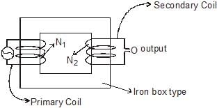
A practical transformer consists of two coils of insulated copper (or aluminium) wire with different numbers of turns, wound on a common soft-iron core. The coil to which electrical energy is supplied is called the primary, and the coil from which electrical energy is taken is called the secondary. The iron core provides a low reluctance path so that most of the magnetic flux links both coils.
To reduce energy loss from circulating currents in the core (eddy currents), the core is made of thin laminated sheets of silicon steel, insulated from each other. The high magnetic permeability of soft iron concentrates the flux and ensures good coupling between the coils.
Types of winding arrangements
- Core type: Primary and secondary coils are wound on separate limbs of a rectangular or square laminated core so that each winding surrounds a different limb.
- Shell type: Primary and secondary coils are wound concentric or one over the other on the same limb of the laminated core so that the core surrounds the windings on both sides.
Theory (ideal transformer, open-circuit secondary)
Consider an ideal transformer with primary turns N₁ and secondary turns N₂. Let φ (phi) be the magnetic flux linked with each turn at any instant.


For sinusoidal or arbitrary flux variation, the instantaneous induced emf in a coil of N turns is proportional to N(dφ/dt). From the induced emfs in primary and secondary we obtain the fundamental relation between voltages and turns:

The ratio N₂/N₁ is the turns ratio or transformation ratio.

For a step-up transformer N₂ > N₁. For a step-down transformer N₁ > N₂.
For a sinusoidal flux with peak value Φm and frequency f, the rms induced emf per turn is given by E(1) = 4.44 f Φm (this gives the commonly used transformer emf relation E = 4.44 f N Φm for N turns).
Currents in primary and secondary (ideal transformer)
Assuming an ideal transformer (no losses, perfect coupling), input power equals output power:
Vp Ip = Vs Is
Thus voltages and currents are related by the turns ratio:

Equivalently, Vs/ Vp = N₂/N₁ and Ip/Is = N₂/N₁ (so current is inversely proportional to turns for an ideal transformer).
Performance: losses and efficiency
Efficiency (η) of a transformer is defined as the ratio of output power to input power, usually expressed as a percentage:

Typical practical transformer efficiencies are high (about 90%-98%), but never 100% because of various losses:
- Copper loss (I²R loss) in the windings due to the resistance of the coil conductors; varies with load.
- Core loss (also called iron loss), consisting of hysteresis loss in the magnetic material and eddy current loss in the core; largely independent of load and depends on flux density and frequency.
- Leakage flux that does not link both windings causing imperfect coupling and voltage drop under load.
- Stray losses such as dielectric losses, mechanical vibrations and cooling losses.
Mitigation measures: laminating the core to reduce eddy currents, using low-hysteresis silicon steel, and using conductors of adequate cross-section to reduce copper losses. Voltage regulation of a transformer describes the change in secondary voltage between no-load and full-load conditions and is related to the equivalent series impedance (leakage reactance and winding resistance).
Ideal versus practical transformer
- Ideal transformer: no winding resistance, no core loss, perfect flux linkage; V and I follow exact relations V ∝ N and I ∝ 1/N; 100% efficient.
- Practical transformer: has winding resistance, leakage flux, core losses; therefore efficiency < 100% and voltage regulation is finite.
Applications
- Transmission and distribution of electrical energy - step-up transformers at generating stations and step-down transformers at receiving substations and consumer premises.
- Isolation transformers for safety and signal isolation.
- Impedance matching in audio, radio-frequency and power electronics.
- Specialised transformers such as autotransformers, instrument transformers (current and potential transformers) used for measurement and protection.
Practical notes and keywords
- Turns ratio determines voltage ratio.
- EMF equation (sinusoidal flux): E(rms) = 4.44 f N Φm.
- Step-up increases voltage and decreases current for same power; step-down decreases voltage and increases current.
- Use of laminated core reduces eddy current loss.
Extra Portion For IIT-Mains
Explain with the help of a labelled diagram, the principle and working of an a.c. generator ? Write the expression for the emf generated in the coil in terms of speed of rotation. Can the current produced by an a.c. generator be measured with a moving coil galvanometer.
Sol. AC generator : A dynamo or generator is a device which converts mechanical energy into electrical energy. It is based on the principle of electromagnetic induction.
Construction of a simple AC generator
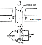
The main parts are:
- Field magnet: Produces the magnetic field. For small generators this may be a permanent magnet; for large machines it is produced by field windings (electromagnets).
- Armature: A coil of insulated wire placed on a rotating drum or ring made of soft iron. As the armature rotates, the flux linked with the coil changes, inducing an emf.
- Slip rings: Two conducting rings (R₁ and R₂) connected to the ends of the armature coil. They rotate with the armature and provide a continuous contact to the external circuit while allowing rotation.
- Brushes: Stationary conductive blocks (carbon or metal) that press against the rotating slip rings to provide electrical contact to the external circuit and transfer the induced current to the load RL.
Working: When the armature coil rotates in a steady magnetic field, the magnetic flux through the coil changes with time. By Faraday's law, an emf is induced in the coil. The direction of the induced emf and current reverses after each half rotation of the coil, producing an alternating emf in the external circuit. The direction of induced emf in each side of the coil is determined by Fleming's right-hand rule.
If N is the number of turns in the coil, A the area of each turn, B the magnetic flux density (magnetic induction), and the coil rotates with angular speed ω (radians per second), then the magnetic flux through the coil at time t is Φ(t) = BAN cos(ωt) for a single-turn effective flux; differentiating gives the induced emf. For N turns and rotation frequency f (f = ω/2π):
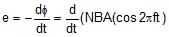
Thus the emf produced is alternating (sinusoidal for uniform rotation in a uniform field), and the current in the external circuit is also alternating.
Can the current produced by an AC generator be measured with a moving-coil galvanometer?
No. A moving-coil galvanometer measures the average (dc) deflection produced by a steady current. The average value of an alternating current over a full cycle is zero, so a moving-coil galvanometer will show no net deflection for a pure AC unless rectification or a suitable detector is used.
FAQs on Transformers
| 1. What are transformers used for? |  |
| 2. How do transformers work? | |
| 3. What is the difference between step-up and step-down transformers? | |
| 4. What are the different types of transformers? | |
| 5. What are the advantages and disadvantages of transformers? | |


