Vernier Calipers and Screw Gauge | Physics Class 11 - NEET PDF Download

Vernier Caliper
A caliper is a device used to measure the distance between two opposing sides of an object.
The tips of the caliper are adjusted to fit across the points to be measured and the caliper is then removed and the distance between the tips is measured using a ruler.
The modern Vernier caliper was invented by Joseph R. Brown in 1851.
The Vernier Caliper consists of a main scale fitted with a jaw at one end (figure). Another jaw, containing the Vernier scale, moves over the main scale (slidable). When the two jaws are in contact, the zero of the main scale and the zero of the Vernier scale should coincide. If both the zeros do not coincide, there will be an error called zero error.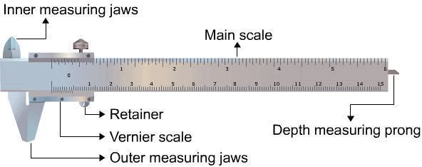 Vernier Caliper
Parts of a Vernier Caliper
1. Main Scale
The main scale consists of a steel metallic strip graduated in centimeters at one edge and in inches at the other edge . It carries the inner and outer measuring jaws.
2. Vernier Scale
A vernier scale slides on the strip. It can be fixed in any position by the retainer. On the Vernier scale, generally, 0.9 cm is divided into ten equal parts.
3. Outer Measuring Jaws
The outer measuring jaws help to take the outer dimension of an object while the inner measuring jaws help to take the inner dimension of an object.
4. Retainer
The retainer helps to retain the object within the jaws of the Vernier calipers
5. Depth Measuring Prong
The depth measuring prong helps to measure the depth of an object
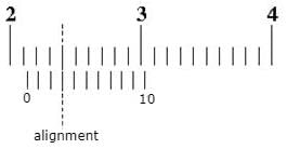
Concept of Least Count
The least count or the smallest reading which you can get with the instrument can be calculated as;Least Count = One Main Scale division (MSD)-One Vernier Scale Division (VSD)
or
Least Count = (One Main scale(MS) division/Number of divisions in Vernier Scale)
First calculate the least count and only then place the object between the two jaws.
Record the position of zero of the Vernier scale on the main scale.
Taking Readings using Vernier Caliper
When a body is between the jaws of the Vernier Caliper; firstly, we need to ensure that the zero of the main scale and the zero of the Vernier scale should coincide. If both the zeros do not coincide, there will be an error called zero error.
Now,
Observe the position of the zero on the Vernier Scale. If the zero of the Vernier scale lies ahead of the Nth division of the main scale, then the main scale reading (MSR) is;
MSR = N
If nth division of Vernier scale coincides with any division of the main scale, then the Vernier scale reading (VSR) is;
VSR = n × L.C, ( L.C is least count of vernier calliper)
Now, the total reading of the length is,
Total Reading (TR)=Main Scale Reading + Vernier Scale Reading
i.e
TR = MSR + VSR = N + (n × L.C) .....(2)
Finding volumes using Vernier Caliper
(a) Volume of a Beaker / Calorimeter
Volume of the beaker / calorimeter = internal area of the cross section x depth
This can be expressed as;
V = π(D/2)2.d
where 'D' is the internal diameter of beaker / calorimeter and 'd' the depth of beaker / calorimeter.
Now, readings of D and d which represents the diameter of cross section and depth respectively can be taken using the Vernier Caliper. The diameter can be measured by clamping the cross section area into the jaws while the depth can be measured using Depth Measuring Prong.
(b) Volume of a Sphere
V = (4/3)πr3
where 'r' is the radius of the sphere.
Measurement of r is done using the Vernier Caliper
(c) Volume of a Rectangular Block
V = l * b * h
where 'l' is length of the block, 'b' the breadth and 'h' the height of the block.
Procedure
(1) We'll first determine the vernier constant (VC), which is the least count (L.C) of the vernier calliper and record it stepwise as in the equation,
L.C = 1 MSD - 1 VSD.
(2) Now, bring the movable jaw in close contact with the fixed jaw and find the zero error. Do this three times and record the values. If there is no zero error, then record 'zero error nil'.
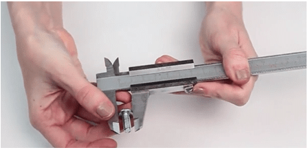
(3) Open the jaws of the Vernier Calliper and place the sphere or cylinder between the two jaws and adjust the movable jaw, such that it gently grips the body without any undue pressure on it. After that, tighten the screw attached to the Vernier scale (figure).
(4) Note the position of the zero mark of the Vernier scale on the main scale. Record the main scale reading just before the zero mark of the Vernier scale. This reading (N) is called main scale reading (MSR).
(5) Note the number (n) of the Vernier scale division which coincides with the division of the main scale.
(6) You'll have to repeat steps 5 and 6 after rotating the body by 90o for measuring the diameter in a perpendicular direction.
(7) Repeat steps 4 to 7 for at least three different positions and record the observations.
(8) Now find total reading using the equation, TR = MSR+VSR = N+(n x L.C) and apply the zero correction.
(9) Take the mean of the different values of the diameter and show that in the result with the proper unit.
Note:
To measure the internal diameter of a calorimeter or beaker, place the beaker upside down over the internal jaws of the vernier calipers.Then repeat the steps 4 to 8.
To find the ‘Depth’ of the beaker, move the metallic strip till it touches the bottom of the beaker. Then repeat steps 4 to 8.
Solved Examples on Vernier Calipers
Q.1. What is the smallest possible reading (in cm) of a Vernier caliper?
Ans.The smallest possible reading of a Vernier caliper is 0.01 cm also called the Least Count of the scale (L.C.).
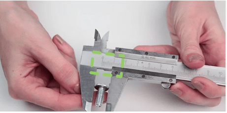
Q.2. A measurement on the Vernier Caliper is made. Report the length of the scale.
Ans.
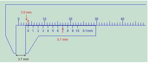 Observe that the Main scale reading (MSR) = 3.0 mm
Also, the 7th division mark on the Vernier scale exactly coincides with the main scale. Hence, Vernier scale reading is 7.
Now, the total reading,
TR = MSR + VSR = N + (n × L.C) ..... (2)
TR = 3.0 mm + (7 × 0.1)mm = 3.7 mm
Hence, the reading recorded would be 3.7 mm.
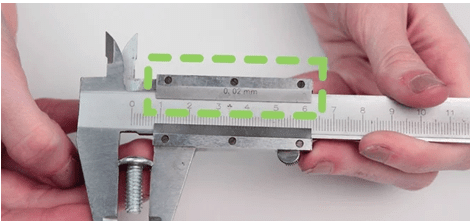
Q.3. A measurement on the Vernier Caliper is made. Report the length of the scale.
Ans.
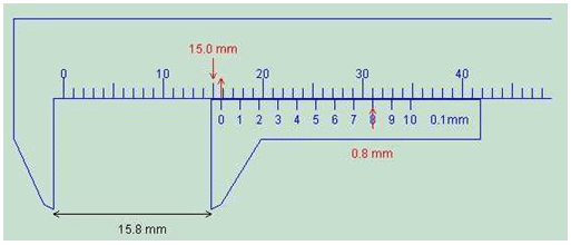
Observe that the Main scale reading (MSR) = 15.0 mm
Also, the 8th division mark on the Vernier scale exactly coincides with the main scale. Hence, Vernier scale reading is 8.
Now, the total reading,
TR = MSR + VSR = N + (n × L.C) ..... (2)
TR = 15.0 mm + (8 × 0.1)mm = 15.8 mm
Hence, the reading recorded would be 15.8 mm.
Using Vernier Calipers allows for accurate length measurements up to 0.1mm. However, for even finer measurements, down to 0.01mm or 0.005mm, a screw gauge surpasses Vernier Calipers in precision. In this document, we will study in detail the screw gauge and its usage followed by calculation techniques.
Screw Gauge
Using Vernier Calipers allows for accurate length measurements up to 0.1mm. However, for even finer measurements, down to 0.01mm or 0.005mm, a screw gauge surpasses Vernier Calipers in precision. In this document, we will study in detail the screw gauge and its usage followed by calculation techniques.
The purpose of screw gauge is:
- To measure the diameter of the given lead shot.
- To measure the diameter of a given wire and find its volume.
- To measure the thickness of a given glass plate and find its volume.
- To measure the volume of an irregular lamina.
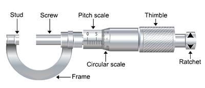
The screw gauge is an instrument used for measuring accurately the diameter of a thin wire or the thickness of a sheet of metal. It consists of a U-shaped frame fitted with a screwed spindle which is attached to a thimble.
 Screw Gauge
Components of Screw Guage
- Parallel to the axis of the thimble, a scale graduated in mm is engraved. This is called the pitch scale. A sleeve is attached to the head of the screw.
- The head of the screw has a ratchet which avoids undue tightening of the screw.
- On the thimble, there is a circular scale known as head scale which is divided into 50 or 100 equal parts. When the screw is worked, the sleeve moves over the pitch scale.
- A stud with a plane end surface called the anvil is fixed on the ‘U’ frame exactly opposite to the tip of the screw. When the tip of the screw is in contact with the anvil, usually, the zero of the head scale coincides with the zero of the pitch scale.
- Pitch of the Screw Gauge
The pitch of the screw is the distance moved by the spindle per revolution. To find this, the distance advanced by the head scale over the pitch scale for a definite number of complete rotations of the screw is determined. The pitch can be represented as;
The pitch of the screw = Distance moved by screw/No. of full rotations given - Least Count of the Screw Gauge
The Least count (LC) is the distance moved by the tip of the screw when the screw is turned through 1 division of the head scale.
The least count can be calculated using the formula;
Least count = (Pitch/Total number of divisions on the circular scale) . - Zero Error and Zero Correction
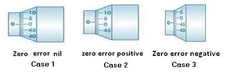
To get the correct measurement, the zero error must be taken into account. For this purpose, the screw is rotated forward till the screw just touches the anvil and the edge of the cap is on the zero mark of the pitch scale. The Screw gauge is held keeping the pitch scale vertical with its zero downwards.
When this is done, any of the following three situations can arise:
(a) The zero mark of the circular scale comes on the reference line. In this case, the zero error and the zero correction, both are nil.
(b) The zero mark of the circular scale remains above the reference line and does not cross it. In this case, the zero error is positive and the zero correction is negative depending on how many divisions it is above the reference line.
(c) The zero mark of the head scale is below the reference line. In this case, the zero error is negative and the zero correction is positive depending on how many divisions it is below the reference line.
To find the diameter of the lead shot with the lead shot between the screw and anvil, if the edge of the cap lies ahead of the Nth division of the linear scale.
Then, linear scale reading (P.S.R.) = N.
If the nth division of the circular scale lies over the reference line.
Then, circular scale reading (H.S.R.) = n × (L.C.) (L.C. is the least count of screw gauge)
Total reading (T.R.) = P.S.R. + corrected H.S.R. = N + (n x L.C.).
If D is the mean diameter of the lead shot,
Then, the volume of the lead shot,
V = (4/3)π (D/2)3
To find the diameter and hence to calculate the volume of the wire
Place the wire between the anvil and the screw and note down the PSR and HSR as before.
The diameter of the wire is given by;
T.R = PSR + (corrected HSR × L.C) = N + (n × L.C) ....(3)
If r is the radius of the wire, and l is the mean length of the wire.
Then, the volume of the wire,
V = π r2 I ....(4)
To find the thickness of the glass plate
The glass plate is gripped between the tip of the screw and the anvil. The PSR and HSR are noted as before.
The thickness of the glass plate is;
t = PSR + corrected HSR = N + (n × L.C) ....(5)
To find the Volume of glass plate (irregular lamina)
Find the thickness, t of irregular lamina as before. Then place the lamina over a graph paper and trace its outline on the graph paper. The area A of the lamina is taken from the graph paper.
The volume of the glass plate is calculated from the equation;
V = A ∗ t ........ (6)
Solved Examples on Screw Gauge
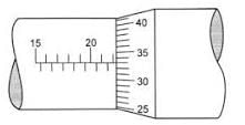
Example 1. What are the readings of the reading of the micrometer meter screw gauges as shown in the figures below?
Solution. Reading of main scale = 4.50 mm
Reading of vernier scale = 10
Reading of Vernier scale x accuracy of Vernier caliper = 10 × 0.01 = 0.10 mm
Add the result of step III and step I to get the reading of the micrometer screw gauge.
= 4.50 + 0.10 = 4.60 mm
Reading of Vernier caliper = 4.60 mm
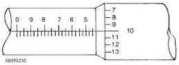
Example 2. What are the readings of the reading of the micrometer meter screw gauges as shown in the figures below?
Solution. Reading of main scale = 22.0 mm
Reading of Vernier scale = 33
Reading of Vernier scale x accuracy of
Vernier caliper = 33 × 0.01 = 0.33 mm
Add the result of step III and step I to get the reading of the micrometer screw gauge.
= 22.0 + 0.33 = 22.33 mm
Reading of Vernier caliper = 22.33 mm
|
95 videos|367 docs|98 tests
|
FAQs on Vernier Calipers and Screw Gauge - Physics Class 11 - NEET
| 1. What are the main parts of a Vernier Caliper? |  |
| 2. What is the concept of Least Count in Vernier Calipers? | |
| 3. How do you take readings using a Vernier Caliper? | |
| 4. How can you find volumes using a Vernier Caliper? | |
| 5. What is the procedure for using a Vernier Caliper to measure an object? | |


Semester Notes
,video lectures
,ppt
,Vernier Calipers and Screw Gauge | Physics Class 11 - NEET
,past year papers
,Previous Year Questions with Solutions
,Exam
,Sample Paper
,Free
,Extra Questions
,Summary
,Important questions
,study material
,Vernier Calipers and Screw Gauge | Physics Class 11 - NEET
,Objective type Questions
,shortcuts and tricks
,mock tests for examination
,Vernier Calipers and Screw Gauge | Physics Class 11 - NEET
,Viva Questions
,practice quizzes
,MCQs
;


Vernier Calipers and Screw Gauge Free PDF Download
Importance of Vernier Calipers and Screw Gauge
Vernier Calipers and Screw Gauge Notes
Vernier Calipers and Screw Gauge NEET Questions
Study Vernier Calipers and Screw Gauge on the App
|
© EduRev
|
Education Revolution
|


|


