Capacitors | Physics Class 12 - NEET PDF Download
| Table of contents |

|
| Capacitors and Capacitance |

|
| Parallel Plate Capacitor |

|
| Effect of Dielectric on Parallel Plate Capacitor |

|
| Combination Of Capacitors |

|
| Energy Stored in a Capacitor |

|
Capacitors and Capacitance
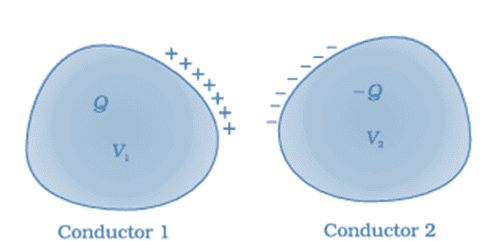 A system of two conductors separated by an insulator forms a capacitor
- The conducting plates have some charges q1 and q2 (Usually if one plate has +q the other has –q charge). The electric field in the region between the plates depends on the charge given to the conducting plates. We also know that potential difference (V) is directly proportional to the electric field hence we can say,
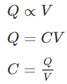
- This constant of proportionality is known as the capacitance of the capacitor.
- Capacitance is the ratio of the change in the electric charge of a system, to the corresponding change in its electric potential.
- The capacitance of any capacitor can be either fixed or variable depending on their usage. From the equation, it may seem that ‘C’ depends on charge and voltage. Actually, it depends on the shape and size of the capacitor and also on the insulator used between the conducting plates.
Standard Units of Capacitance
The basic unit of capacitance is Farad. But, Farad is a large unit for practical tasks. Hence, capacitance is usually measured in the sub-units of Farads such as micro-farads (µF) or pico-farads (pF).
Most of the electrical and electronic applications are covered by the following standard unit (SI) prefixes for easy calculations:
- 1 mF (millifarad) = 10−3 F
- 1 μF (microfarad) =10−6 F
- 1 nF (nanofarad) = 10−9 F
- 1 pF (picofarad) = 10−12 F
Parallel Plate Capacitor
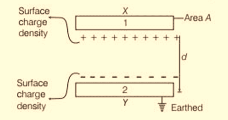 Parallel Plate Capacitor
- The parallel plate capacitor as shown in the figure has two identical conducting plates, each having a surface area A and separated by a distance d.
- When voltage V is applied to the plates, it stores charge Q. The force between charges increases with charge values and decreases with the distance between them.
- The bigger the area of the plates, the more charge they can store. Hence, the value of C is greater for a large value of A. Similarly, the closer the plates are, the greater the attraction of the opposite charges on them. Therefore C is greater for a smaller d.
- The charge density on the plates is given by the formula:

- When the distance of separation (d) is small, the electric field between the plates is fairly uniform and its magnitude is given by:

- As the electric field between the plates is uniform, the potential difference between the plates is given by

- Substituting the above value of V in the capacitance formula, we get

- The capacitance of a parallel plate capacitor is given by the formula

Example 1: Calculate the capacitance of an empty parallel-plate capacitor that has metal plates with an area of 1.00 m2, separated by 1.00 mm?
Sol: Using the formula, we can calculate the capacitance as follows:
Substituting the values, we get
Applications of Capacitors
➢ Capacitors for Energy Storage
- Since the late 18th century, capacitors are used to store electrical energy. Individual capacitors do not hold a great deal of energy, providing only enough power for electronic devices to use during temporary power outages or when they need additional power.
- There are many applications that use capacitors as energy sources and a few of them are as follows:
(i) Audio equipment
(ii) Camera Flashes
(iii) Power supplies
(iv) Magnetic coils
(v) Lasers - Supercapacitors are capacitors that have high capacitances up to 2 kF. These capacitors store large amounts of energy and offer new technological possibilities in areas such as electric cars, regenerative braking in the automotive industry and industrial electrical motors, computer memory backup during power loss, and many others.
➢ Capacitors for Power Conditioning
- One of the important applications of capacitors is the conditioning of power supplies. Capacitors allow only AC signals to pass when they are charged blocking DC signals.
- This effect of a capacitor is majorly used in separating or decoupling different parts of electrical circuits to reduce noise, as a result of improving efficiency. Capacitors are also used in utility substations to counteract inductive loading introduced by transmission lines.
➢ Capacitors as Sensors
- Capacitors are used as sensors to measure a variety of things including humidity, mechanical strain, and fuel levels. Two aspects of capacitor construction are used in the sensing application – the distance between the parallel plates and the material between them.
- The former is used to detect mechanical changes such as acceleration and pressure and the latter is used in sensing air humidity.
➢ Capacitors for Signal Processing
- There are advanced applications of capacitors in information technology. Capacitors are used by Dynamic Random Access Memory (DRAM) devices to represent binary information as bits.
- Capacitors are also used in conjunction with inductors to tune circuits to particular frequencies, an effect exploited by radio receivers, speakers, and analog equalizers.
Effect of Dielectric on Parallel Plate Capacitor
Consider a dielectric is inserted between the plates of a parallel plate capacitor and fully occupying the intervening region as shown in figure. The dielectric is polarised by the field, with surface charge densities σp and −σp.
The electric field in the dielectric then corresponds to the case when the net surface charge density on the plates is ±(σ−σp).
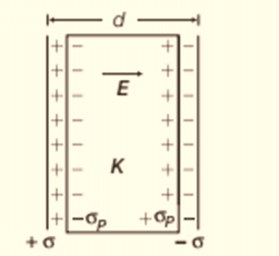 Dielectric between the plates of a capacitor
So, net electric field between the plates, 
[∵ dielectric is polarised in the opposite direction of external field]
∴ Potential difference between the plates, 
For linear dielectrics, we expect σp to be proportional to E0 i.e. to σ.
Thus, (σ − σp) is proportional to σ and we can write,

where, K is a constant characteristics of the dielectric.
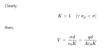
∴ The capacitance C with dielectric between the plates is given by

The product ε0K is called the permittivity of the medium and is denoted by ε i.e.

For vacuum, K=1 and ε=ε0, where ε0 is called the permittivity of the vacuum.
The dimensionless ratio,
is called the dielectric constant of the substance. Similarly,

Thus, the dielectric constant of a substance is the factor (K>1) by which the capacitance increases from its vacuum value, when the dielectric is inserted fully between the plates of a capacitor.
(i) When a dielectric slab of thickness t is inserted between the plates, then

(ii) If several slabs of dielectric constants K1, K2, K3,... and respective thicknesses t1 ,t2 ,t3, ... are placed in between the plates of a capacitor, then capacitance,

Combination Of Capacitors
Capacitors combination can be made in many ways. The combination is connected to a battery to apply a potential difference (V) and charge the plates (Q). We can define the equivalent capacitance of the combination between two points to be: C = Q/V
Two frequently used methods of combination are:
- Parallel combination
- Series combination
Parallel Combination of Capacitors
When one plate of one capacitor is connected with one plate of the other capacitor, such combination is called parallel combination.
All capacitors have the same potential difference but different charges.
We can say that : Q1 = C1V
Q1 = Charge on capacitor C1
C1 = Capacitance of capacitor C1 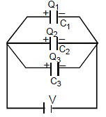
V = Potential across capacitor C1
The charge on the capacitor is proportional to its capacitance Q µ C


Where Q = Q1 + Q2 + Q3 ..............
Key Points:
- The maximum charge will flow through the capacitor of the largest value.
- Equivalent capacitance of parallel combination, Ceq = C1 + C2 + C3
- Equivalent capacitance is always greater than the largest capacitor of combination.
- Half of the energy supplied by the battery is stored in the form of electrostatic energy and half of the energy is converted into heat through resistance.
- Energy stored in the combination :


Formulae Derivation for Parallel combination
A parallel combination of three capacitors, with one plate of each capacitor connected to one side of the circuit and the other plate connected to the other side, is illustrated in Figure.
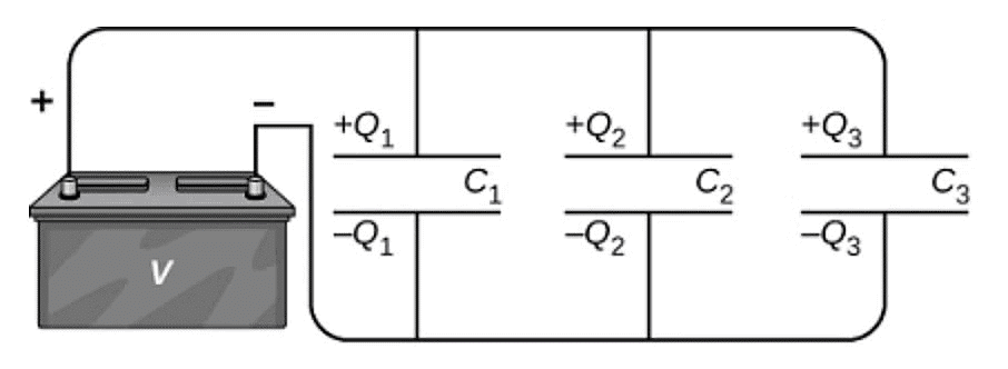
Since the capacitors are connected in parallel, they all have the same voltage V across their plates. However, each capacitor in the parallel network may store a different charge. To find the equivalent capacitance 𝐶𝑝 of the parallel network, we note that the total charge Q stored by the network is the sum of all the individual charges:
𝑄 = 𝑄1 + 𝑄2 + 𝑄3
On the left-hand side of this equation, we use the relation 𝑄 = 𝐶𝑝𝑉, which holds for the entire network. On the right-hand side of the equation, we use the relations
𝑄1 = 𝐶1𝑉 , 𝑄2 = 𝐶2𝑉 , and 𝑄3 = 𝐶3𝑉 for the three capacitors in the network.
In this way we obtain 𝐶𝑝𝑉 = 𝐶1𝑉 + 𝐶2𝑉 + 𝐶3𝑉.
This equation, when simplified, is the expression for the equivalent capacitance of the parallel network of three capacitors: 𝐶𝑝 = 𝐶1 + 𝐶2 + 𝐶3
This expression is easily generalized to any number of capacitors connected in parallel in the network.
Series Combination of Capacitors
When initially uncharged capacitors are connected as shown, then the combination is called series combination
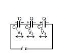
All capacitors will have the same charge but different potential difference across them.
We can say that 
V1 = potential across C1
Q = charge on positive plate of C1
C1 = capacitance of capacitor similarly

V1 : V2 : V3 = 
We can say that potential difference across capacitor is inversely proportional to its capacitance in series combination.

Key Points:
- In a series combination, the smallest capacitor gets maximum potential.
-
 ,
,  ,
,  Where V = V1 + V2 + V3
 - Equivalent Capacitance:
Equivalent capacitance of any combination is that capacitance which when connected in place of the combination stores the same charge and energy as that of the combination
In series:
- In series, the combination equivalent is always less than the smallest capacitor of the combination.
- Half of the energy supplied by the battery is stored in form of electrostatic energy and half of the energy is converted into heat through resistance.
- Energy stored in the combination:
Ucombination =
- Ucombination =

- The energy supplied by the battery in charging the combination Ubattery = Q × V = Q .
 =
= 

Formulae Derivation for Series combination
Let the capacitance of each capacitor be C1, C2 and C3 and their equivalent capacitance is Ceq.
As these capacitors are connected in series, thus charge across each capacitor is same as Q. When some electrical components, let say 3, are connected in series with each other, the potential difference of the battery V gets divided across each component as
V1, V2 and V3 as shown in the figure.

∴ V = V1 + V2 + V3
Using V = Q/C

Equivalent capacitance for series combination = 
In general, 
Example 2: Find charge on each capacitor.
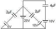
Sol: Charge on C1 = C1V1 = 2 × (20 - 5)μC
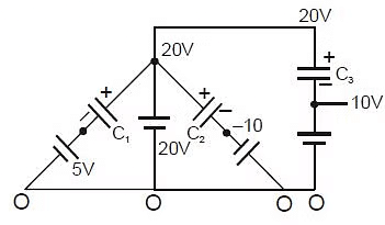
= 30 μC
Charge on C2 = C2V2 = 2 × (20 - (-10))μC
= 60 μC
Charge on C3 = C3V3 = 4 × (20 - 10)μC
= 40 μC
Example 3: Find charge on each capacitor.
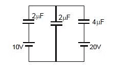
Sol: Charge on C1 = (x - 10) C1
Charge on C2 = (x - 0) C2
Charge on C3 = (x - 20) C3
Now from charge conservation at node x
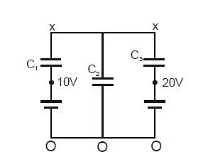
(x - 10)C1 (x - 0)C2 (x - 20)C3 = 0
⇒ 2x - 20 2x 4x - 80 = 0
⇒ x = 25 Therefore
so 

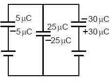

Example 4: In the given circuit find out the charge on each capacitor. (Initially they are uncharged)
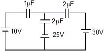
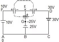
Sol: Let potential at A is 0, so at D it is 30 V, at F it is 10 V and at point G potential is -25V. Now apply Kirchhoff's Ist law at point E. (total charge of all the plates connected to 'E' must be same as before i.e. 0)
Therefore, (x - 10) + (x - 30) 2 +(x 25) 2 = 0
5x = 20
x = 4
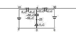
Final charges:
Q2mF = (30 - 4) 2 = 52 mC
Q1mF = (10 - 4) = 6 mC
Q2mF = (4 - (-25)) 2 = 58 mC
Example 5:
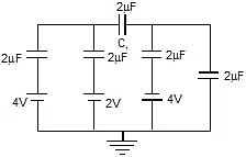
Find voltage across capacitor C1.
Sol:
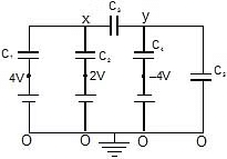
Now from charge conservation at node x and y
For x:
(x - 4)C1 + (x - 2)C2 + (x - y)C3 = 0 ⇒
2(x - 4) + 2(x - 2) (x - y) 2 = 0
6x - 2y - 12 = 0 .....(1)
For y:
(y - x)C3 + [y -(-4)]C4 (y - 0)C5 = 0 ⇒ (y - x)2 (y 4) 2 y 2 = 0
= 6y - 2x 8 = 0 .....(2)
eq. (1) & (2)
y = - 3 Therefore
x = 7 Therefore
So potential difference = x - y = 

Example 6: Three initially uncharged capacitors are connected in series as shown in circuit with a battery of emf 30V. Find out following :
(i) charge flow through the battery,
(ii) potential energy in 3 mF capacitor.
(iii) Utotal in capacitors
(iv) heat produced in the circuit
Sol: 
Ceq = 1 μF.
(i) Q = Ceq V = 30 μC
(ii) charge on 3μF capacitor = 30 μC
energy =  =
=  = 150 μJ
(iii) Utotal =  = 450 μJ
(iv) Heat produced = (30 μC) (30) - 450 μJ = 450 μJ
Example 7: Two capacitors of capacitance 1 mF and 2mF are charged to potential difference 20 V and 15 V as shown in figure. If now terminal B and C are connected together terminal A with positive of battery and D with negative terminal of battery then find out final charges on both the capacitor.


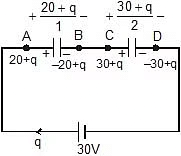
Sol: Now applying kirchhoff voltage law,

- 40 - 2q - 30 - q = - 60
3q = - 10
Charge flow = -  μC.
μC.
Charge on capacitor of capacitance 1μF = 20 q = 
Charge on capacitor of capacitance 2μF = 30 q = 
Energy Stored in a Capacitor
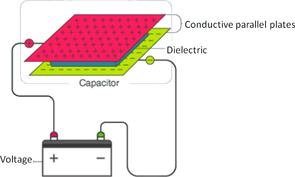
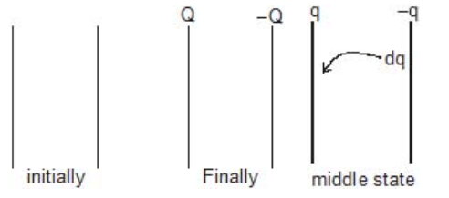
Work has to be done in charging a conductor against the force of repulsion by the already existing charges on it. The work is stored as a potential energy in the electric field of the conductor.
Suppose a conductor of capacity C is charged to a potential V0 and let q0 be the charge on the conductor at this instant. The potential of the conductor when (during charging) the charge on it was q (< q0) is,
Now, work done in bringing a small charge dq at this potential is,
Therefore, total work done in charging it from 0 to q0 is,
This work is stored as the potential energy,
Therefore,
Further by using q0 = CV0 we can write this expression also as,
In general if a conductor of capacity C is charged to a potential V by giving it a charge q, then
Change in Energy on Introducing a Dielectric Slab
(i) When a dielectric slab is inserted between the plates of a charged capacitor, with battery connected to its plates. Then, the capacitance becomes K (dielectric constant) times and energy stored in the capacitor becomes KU0.
(ii) When a dielectric slab is inserted between the plates of a charged capacitor and battery is disconnected. Then, the charge on the plates remains unchanged and energy stored in the capacitor becomes  i.e., energy decreases.
Example 8: At any time S1 switch is opened and S2 is closed then find out heat generated in circuit.
Sol:
Charge flow through battery = Qf - Qi
= 2CV - CV = CV
H = (CV × 2V) -
Distribution of Charges on Connecting two Charged Capacitors :
When two capacitors C1 and C2 are connected as shown in figure
Before connecting the capacitors | ||
Parameter | Ist Capacitor | IInd Capacitor |
Capacitance | C1 | C2 |
Charge | Q1 | Q2 |
Potential | V1 | V2 |
After connecting the capacitors | ||
Parameter | Ist Capacitor | IInd Capacitor |
Capacitance | C1 | C2 |
Charge | ||
Potential | V1 | V2 |
(a) Common potential :
By charge conservation on plates A and C before and after connection.
Q1 + Q2 = C1V + C2V
⇒ =
(b)
(b) Heat loss during redistribution :
The loss of energy is in the form of Joule heating in the wire.
- When plates of similar charges are connected with each other ( with and - with -) then put all values (Q1, Q2, V1, V2) with positive sign.
- When plates of opposite polarity are connected with each other ( with -) then take charge and potential of one of the plate to be negative.
Derivation of above formulae :
Let potential of B and D is zero and common potential on capacitors is V, then at A and C it will be V.
C1V + C2V = C1V1 + C2V2
=
H =
When oppositely charged terminals are connected, then
Therefore, C1V C2V = C1V1 - C2V2
Example 9: Find out the following if A is connected with C and B is connected with D.
(i) How much charge flows in the circuit.
(ii) How much heat is produced in the circuit.
Sol: Let potential of B and D is zero and common potential on capacitors is V, then at A and C it will be V.
By charge conservation,
3V + 2V = 40 + 30
5V = 70 ⇒ V = 14 volt
Charge flow = 40 - 28 = 12 μC
Now final charges on each plate is shown in the figure.
(ii) Heat produced = × 2 × (20)2
× 3 × (10)2 -
× 5 × (14)2
= 400 150 - 490
= 550- 490 = 60 mJ
Example 10: Repeat above question if A is connected with D and B is connected with C.
Sol: Let potential of B and C is zero and common potential
on capacitors is V, then at A and D it will be V
2V + 3V = 10 ⇒ V = 2 volt
Now charge on each plate is shown in the figure.
Heat produced = 400 + 150 - 1
Therefore 2 × 5 × 4
= 550 - 10 = 540 μJ
|
74 videos|314 docs|88 tests
|
FAQs on Capacitors - Physics Class 12 - NEET
| 1. What is a parallel plate capacitor and how does it work? |  |
| 2. What are the main applications of capacitors in electronic circuits? |  |
| 3. How does a dielectric material affect the capacitance of a parallel plate capacitor? |  |
| 4. How do you calculate the equivalent capacitance for capacitors in parallel? |  |
| 5. What is the method to find the equivalent capacitance of capacitors in series? |  |


