Electromagnetic Induction: Part 1 | Physics Class 12 - NEET PDF Download
| Table of contents |

|
| The Experiments of Faraday And Henry |

|
| Magnetic Flux |

|
| Faraday's Law of Induction |

|
| Lenz's Law |

|
| Motional Electromotive Force |

|
| Eddy Currents |

|
Introduction
- Electric current can be induced in coils when they are rotated within a magnetic field, providing an alternative way to generate current.
- Before the discovery of electromagnetic induction, the only sources of electromotive force (emf) were chemical, such as dry cells.
- However, the discovery of electromagnetic induction (EMI) enabled large-scale energy production and distribution.
- Faraday and Henry independently discovered the concept of magnetically induced emf and developed methods to convert mechanical energy into electrical energy.
- This discovery laid the foundation for two major electrical devices— the electric generator and the transformer—both of which have significantly transformed modern life.
The Experiments of Faraday And Henry
Experiment 1
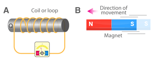
- In this experiment, Faraday connected a coil to a galvanometer, as shown in the figure above.
- A bar magnet was pushed towards the coil, such that the north pole is pointing towards the coil.
- As the bar magnet is shifted, the pointer in the galvanometer gets deflected, thus indicating the presence of current in the coil under consideration.
- It is observed that when the bar magnet is stationary, the pointer shows no deflection and the motion lasts only till the magnet is in motion.
- Here, the direction of the deflection of the pointer depends upon the direction of motion of the bar magnet.
- Also, when the south pole of the bar magnet is moved towards or away from the coil, the deflections in the galvanometer are opposite to that observed with the north pole for similar movements.
- Apart from this, the deflection of the pointer is larger or smaller depending upon the speed with which it is pulled towards or away from the coil.
- The same effect is observed when instead of the bar magnet, the coil is moved and the magnet is held stationary.
- This shows that only the relative motion between the magnet and the coil are responsible for the generation of current in the coil.
Experiment 2
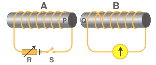
- In the second experiment, Faraday replaced the bar magnet by a second current-carrying coil that was connected to a battery.
- Here, the current in the coil due to the connected battery produced a steady magnetic field, which made the system analogous to the previous one.
- As we move the second coil towards the primary coil, the pointer in the galvanometer undergoes deflection, which indicates the presence of the electric current in the first coil.
- Similar to the above case, here too, the direction of the deflection of the pointer depends upon the direction of motion of the secondary coil towards or away from the primary coil.
- Also, the magnitude of deflection depends upon the speed with which the coil is moved.
- All these results show that the system in the second case is analogous to the system in the first experiment.
Experiment 3
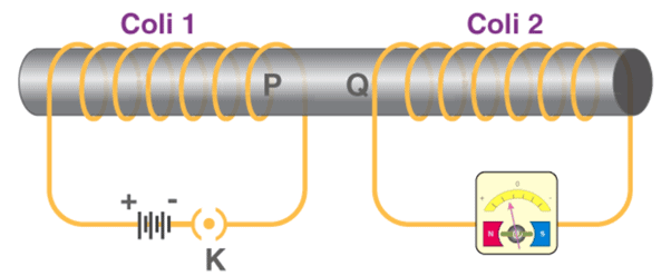
- From the above two experiments, it was concluded by Faraday that the relative motion between the magnet and the coil resulted in the generation of current in the primary coil.
- But another experiment conducted by Faraday proved that the relative motion between the coils was not really necessary for the current in the primary to be generated.
- In this experiment, he placed two stationary coils and connected one of them to the galvanometer and the other to a battery, through a push-button.
- As the button was pressed, the galvanometer in the other coil showed a deflection, indicating the presence of current in that coil.
- Also, the deflection in the pointer was temporary and if pressed continuously, the pointer showed no deflection and when the key was released, the deflection occurred in the opposite direction.
Magnetic Flux
Magnetic flux represents the total number of magnetic field lines passing normally through a given surface when it is placed in a magnetic field.
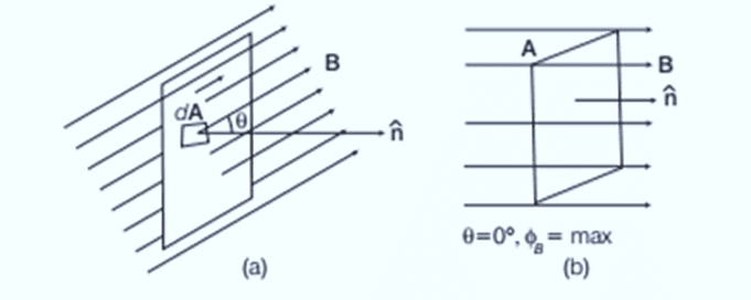
Suppose a loop with area A is in a uniform magnetic field BBB. The magnetic flux ϕB through the loop is:
When the magnetic field is perpendicular to the surface of the loop, the flux is maximized:

This relationship implies that the magnetic field strength B is the magnetic flux per unit area, termed magnetic flux density or magnetic induction.
If the magnetic field B makes an angle θ with the normal to the area A, the magnetic flux is:

where θ is the angle between B and A.
- If the plane is parallel to the magnetic field, no field lines pass through, so magnetic flux is zero.
- Magnetic flux can be altered by changing B, A, or the angle θ, or by reshaping or rotating the coil in a magnetic field.

Faraday's Law of Induction
Whenever the flux of the magnetic field through the area bounded by a closed conducting loop changes, an electromotive force (emf) is produced in the loop. The emf (ε) is given by:
ε=−dΦB/dt
where ΦB is the magnetic flux through the area. The negative sign indicates the direction of the induced emf, which opposes the change in magnetic flux (Lenz's Law).
The magnetic flux (ΦB) through the area is defined as:
ΦB=B⋅A⋅cos(θ)
where:
- B is the magnetic field strength
- A is the area bounded by the loop
- θ is the angle between the magnetic field and the normal to the loop's surface
The emf so produced drives an electric current (I) through the loop. If the resistance of the loop is R, then the current is given by:
Substituting the expression for emf, we get:
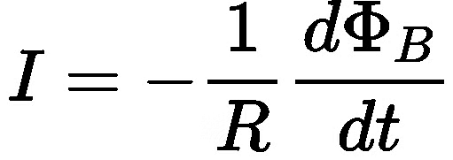
This is Faraday's law of electromagnetic induction, combined with Ohm's law, showing how the induced emf leads to an electric current in the loop
Example 1. A coil is placed in a constant magnetic field. The magnetic field is parallel to the plane of the coil as shown in figure. Find the emf induced in the coil.

Sol. f = 0 (always) since area is perpendicular to magnetic field.
Therefore, emf = 0
Example 2. Find the emf induced in the coil shown in figure. The magnetic field is perpendicular to the plane of the coil and is constant.

Sol. f = BA (always) = const.
Therefore, emf = 0
Lenz's Law
The effect of the induced emf is such as to oppose the change in flux that produces it.
 (a) (b)
  (c) (d)
- In figure (a & b) as the magnet approaches the loop, the flux through the loop increases. The induced current sets up an induced magnetic field Bind whose flux opposes this change. The direction of Bind is opposite to that of the external field Bext due to the magnet.
- In figure (c & d) the flux through the loop decreases as the magnet moves away from the loop. The flux due to the induced magnetic field tries to maintain the flux through the loop. The direction of Bind is the same as that of Bext due to the magnet.
- Lenz's law is closely related to the law of conservation of energy and is actually a consequence of this general law of nature. As the north pole of the magnet moves towards the loop, an induced current is produced. This opposes the motion of the N-pole of the bar magnet. Thus, in order to move the magnet toward the loop with a constant velocity, an external force must be applied. The work done by this external force gets transformed into electric energy, which induces current in the loop.
- There is another alternative way to find the direction of the current inside the loop, which is described below.
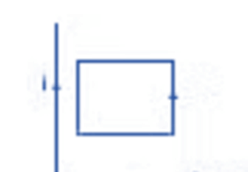
- The figure shows a conducting loop placed near a long, straight wire carrying a current i as shown. If the current increases continuously, then there will be an emf induced inside the loop.
- Due to this induced emf, an electric current is induced. To determine the direction of the current inside the loop, we put an arrow as shown. The right-hand thumb rule shows that the normal to the loop is going into the plane.
- Again, the same rule shows that the magnetic field at the site of the loop is also going into the plane of the diagram.
- Thus B and dA are in the same direction. Therefore, ∫Φ • idA is positive if i increases, the magnitude of fluxΦ increases.
- Since magnetic fluxΦ is positive and its magnitude increases, dΦ/dt is positive. Thus ε is negative, and hence the current is negative.
- Thus the current induced is opposite to that of the arrow.
Example 3. Find the direction of induced current in the coil shown in figure. Magnetic field is perpendicular to the plane of coil and it is increasing with time.

Sol. Inward flux is increasing with time. To oppose it outward magnetic field should be induced. Hence current will flow in anticlockwise.
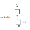
Example 4. Figure shows a long current carrying wire and two rectangular loops moving with velocity v. Find the direction of current in each loop.
Sol. In loop (i) no emf will be induced because there is no flux change.
In loop (ii) emf will be induced because the coil is moving in a region of decreasing magnetic field inward in direction. Therefore to oppose the flux decrease in inward direction, current will be induced such that its magnetic field will be inwards. For this direction of current should be clockwise.
By changing the magnetic field
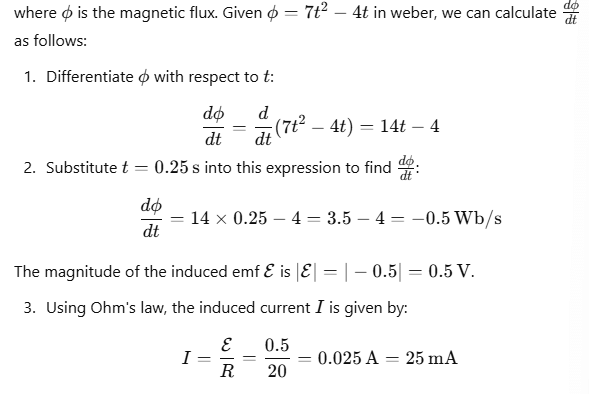
Example 5. The magnetic flux (φ2) in a closed circuit of resistance 20 W varies with time (t) according to the equation f = 7t2 - 4t where f is in weber and t is in seconds. The magnitude of the induced current at t = 0.25 s is
(A) 25 mA (B) 0.025 mA (C) 47 mA (D) 175 mA
Sol. To find the induced current at t=0.25s, we start by using Faraday's law of electromagnetic induction, which states that the induced emf E in a closed circuit is given by:

Example 6. Consider a long infinite wire carrying a time varying current i = kt (k > 0). A circular loop of radius a and resistance R is placed with its centre at a distance d from the wire (a < < d). Find out the induced current in the loop?
Sol. Since current in the wire is continuously increasing therefore we conclude that magnetic field due to this wire in the region is also increasing.
Magnetic field B due to wire 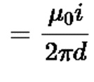 going into and perpendicular to the plane of the paper
Flux through the circular loop,
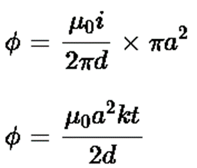
Induced e.m.f. in the loop

Induced current in the loop 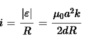
Direction of induced current in the loop is anticlockwise.
Brain Teaser :
A copper ring is held horizontally and a bar magnet is dropped through the ring with its length along the axis of the ring. Will the acceleration of the falling magnet be equal to, greater than or lesser than the acceleration due to gravity ?
By Changing the Area
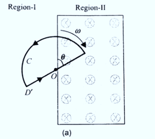
Example 7. A space is divided by the line AD into two regions. Region I is field free and the region II has a uniform magnetic field B directed into the paper. ACD is a semicircular conducting loop of radius r with centre at O, the plane of the loop being in the plane of the paper. The loop is now made to rotate with a constant angular velocity w about an axis passing through O, and perpendicular to the plane of the paper in the clockwise direction. The effective resistance of the loop is R.
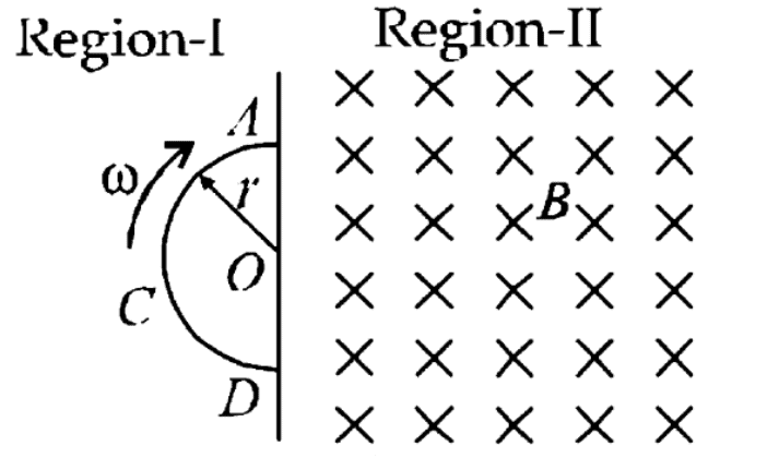
(a) Obtain an expression for the magnitude of the induced current in the loop.
(b) Show the direction of the current when the loop is entering into the region II.
(c) Plot a graph between the induced emf and the time of rotation for two periods of rotation.
Sol. (a) When the loop is rotated about an axis passing through center O and perpendicular to the plane of the paper, the angle between magnetic field vector B and area A is always 0∘. When the loop =Ba cos0=0 the (Since B=0 in region I).
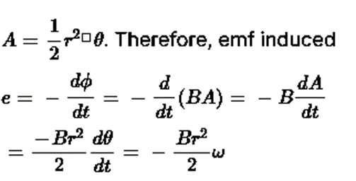
When the loop enters the magnetic field in region II, the magnetic flux linked with it is given by ϕ=BA where
As resistance of the loop is R, the current induced is given by

This is the required expression for current induced in the loop.
(b) According to Lenz's law, the direction of current induced is to oppose the change in magnetic flux. So, when entering into region II the field produced by the current induced anticlockwise as shown in figure.
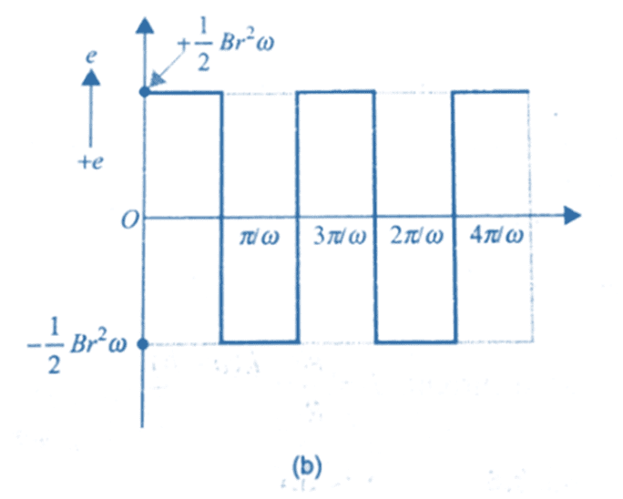 ( c) When the loop enters the magnetic flux linked with it increases and the emf
  is induced in one direction. when the loop comes out of the field the flux decreases and emf is induced in opposite sense. The graph for representing the emf induced versus time for two taken anticlockwise direction as positive.
Motional Electromotive Force
Consider a uniform magnetic field B limited to the region ABCD, with a coil PQRS positioned inside this field. At any moment t, the section of the coil P′Q=S′R=y is within the magnetic field, where l represents the length of the coil’s arm.
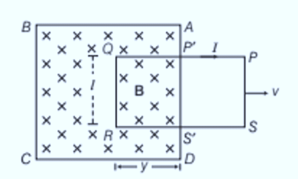
The area of the coil within the magnetic field at time t is:
The magnetic flux ϕ through the coil at this time is:
The rate of change of magnetic flux through the coil is given by:

Using Fleming’s right-hand rule, the current induced by this emf flows from end R to Q along SRQP in the coil. This induced emf, Blv, is known as the motional emf.
Energy Consideration (A Quantitative Study)
Let R be the resistance of the movable arm PQ of an irregular conductor. The other arms QR, RS, and SP are assumed to have negligible resistance compared to R. Therefore, the total resistance of the rectangular loop is R, which remains constant as PQ moves.
The current I in the loop is given by: 
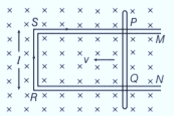
Due to the magnetic field, a force acts on the arm PQ in a direction opposite to its velocity. The magnitude of this force, given by the magnetic force equation, is:

This force expression is identical to the equation for power dissipation. Thus, the mechanical energy required to move the arm PQ is converted into electrical energy and eventually into thermal energy.
Note: The magnetic flux linked with a loop remains unchanged in the following scenarios:
- When both the magnet and the loop move at the same velocity.
- When the magnet rotates around its axis without changing its distance from the loop.
- When the loop is moved within a uniform magnetic field, provided the entire loop stays in the field.
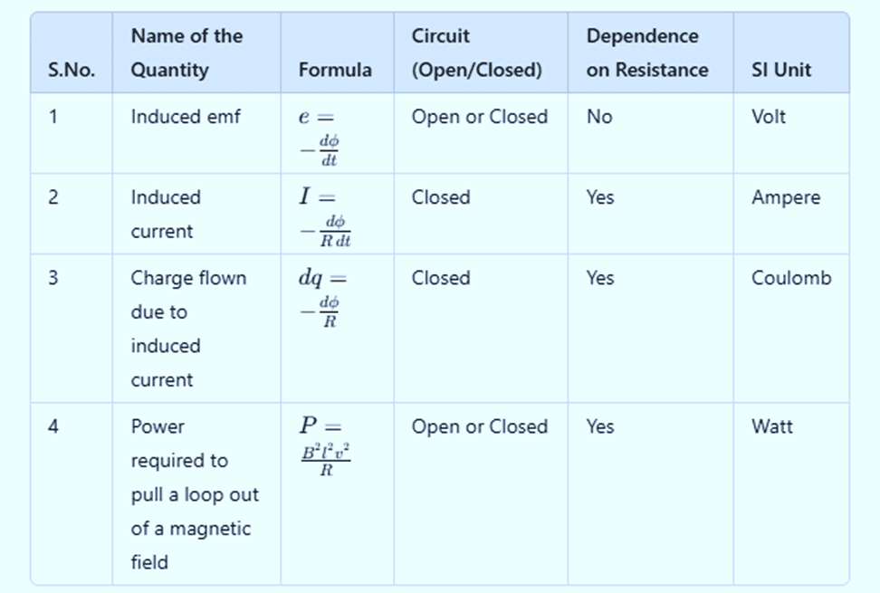 Induced Quantities and Their Formulae
Eddy Currents
When a magnetic flux change occurs in a bulk conductor, it induces currents within the conductor, called eddy currents.
These currents flow in a plane perpendicular to the magnetic field’s direction and generate both heat and magnetic effects.
The magnitude of eddy current I can be calculated as: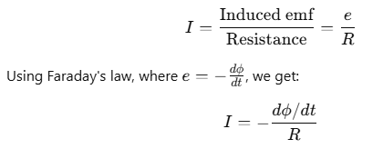
The direction of eddy currents can be determined using Lenz's law or Fleming's right-hand rule. Eddy currents flow in circular patterns resembling swirling eddies in water, hence the name "eddy currents." Discovered by Foucault in 1895, they are also called Foucault currents.
For example, if a metal plate moves out of a magnetic field, the motion between the conductor and magnetic field induces a current within the conductor. The movement of electrons in the conductor creates a circulating eddy current within the plate, behaving like whirlpools in a liquid.
Applications of Eddy Currents
Eddy currents have several practical applications:
- Electromagnetic Damping: To quickly bring the moving coil of a galvanometer to rest, electromagnetic damping is employed, utilizing eddy currents to halt the coil's motion. When the coil oscillates, eddy currents generated in the core oppose the motion, thereby stabilizing the coil.
- Induction Furnace: Eddy currents are used to generate high temperatures in induction furnaces, commonly used for alloy preparation by melting metals. A coil wound around the metal to be melted carries high-frequency alternating current. The eddy currents induced in the metal produce the required heat to melt it.
- Electric Power Meters: Older analog electric power meters included a metallic disc that rotated due to eddy currents. These currents were induced by the sinusoidal currents in the meter's coil.
- Magnetic Braking in Electric Trains: Some electric trains use strong electromagnets placed above the rails to induce eddy currents in the rails. These currents create a magnetic force that opposes the train’s motion, providing a smooth braking effect without mechanical contact.
Solved Questions
Q1. A coil having n turns and area A is initially placed with its plane normal to the magnetic field B. It is then rotated through 180º in 0.2 sec. The emf induced at the ends of the coils is
(a) 0.1 nAB
(b) nAB
(c) 5 nAB
(d) 10 nAB
Ans: (d)
Explanation:
Total change in flux = ΔΦ = 2 nAB
Total time of change = Δt = 0.2s
Emf induced = ΔΦ/Δt = 10nAB
Q2. A straight line conductor of length 0. 4m is moved with a speed of 7ms-1 perpendicular to a magnetic field of an intensity of 0.9wbm-2 The induced emf across the conductor is:
(a) 25.2 V
(b) 5.24 V
(c) 2.52 V
(d) 1.26 V
Ans: (c)
Explanation: The induced emf across the conductor E= Blv
= 0.98 × 0.4 × 7 = 2.52V
Q3. Two conducting rings of radii r and 2r move in opposite directions with velocities 2v and v respectively on a conducting surface S. There is a uniform magnetic field of magnitude B perpendicular to the plane of the rings. The potential difference between the highest points of the two rings is:
(a) Zero
(b) 2rvB
(c) 4rvB
(d) 8rvB
Ans: (d)
Explanation: Replace the emf in the rings by the cells.
E1= B2r(2V) = 4Brv
E2 = B(4r)v = 4Brv
V2 – V1 = 8Brv
|
88 videos|421 docs|88 tests
|
FAQs on Electromagnetic Induction: Part 1 - Physics Class 12 - NEET
| 1. What is Faraday's Law of Induction and how does it work? |  |
| 2. What is Lenz's Law and why is it important in electromagnetic induction? |  |
| 3. How do eddy currents form and what are their effects? |  |
| 4. What is motional electromotive force (EMF) and how is it generated? |  |
| 5. What experiments did Faraday and Henry conduct to demonstrate electromagnetic induction? |  |


