NCERT Exemplar: Electricity | Science Class 10 PDF Download
Multiple Choice Questions
Q.1. A cell, a resistor, a key, and an ammeter are arranged as shown in the circuit diagrams of Figure. The current recorded in the ammeter will be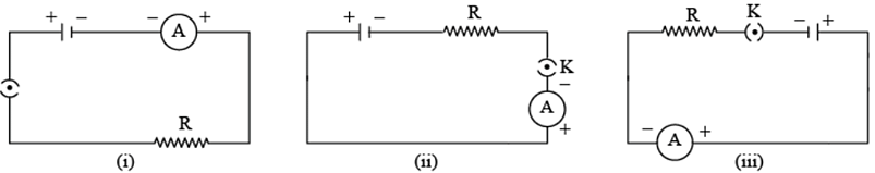 (a) Maximum in (i)
(b) Maximum in (ii)
(c) Maximum in (iii)
(d) The same in all the cases
Correct Answer is Option (a)
Since the resistance is same in all the three circuit diagrams so the current will be same in all the three cases. Hence, the correct answer is option d.
Q.2. In the following circuits (Figure), the heat produced in the resistor or combination of resistors connected to a 12 V battery will be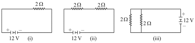 (a) Same in all the cases
(b) Minimum in case (i)
(c) Maximum in case (ii)
(d) Maximum in case (iii)
Correct Answer is Option (c)
Here two transistors are in series. In figure (iii) total resistance will be less than individual resistances as they are connected parallel. Higher resistance produces more heat hence option c) is the right answer.
Q.3. Electrical resistivity of a given metallic wire depends upon
(a) Its length
(b) Its thickness
(c) Its shape
(d) Nature of the material
Correct Answer is Option (d)
The electrical resistivity of a given metallic wire depends upon the nature of the material.
Q.4. A current of 1 A is drawn by a filament of an electric bulb. The number of electrons passing through a cross-section of the filament in 16 seconds would be roughly
(a) 1020
(b) 1016
(c) 1018
(d) 1023
Correct Answer is Option (a)
I = Q/t
Q= It
Q= 1 x 16
Q= 16 q
Q = ne
n = Q/e
n = 16 /1.6 x 10-19
n = 10 x 1019
n = 1020 electrons
The number of electrons flowing is 1020 electrons
Q.5. Identify the circuit (Figure 12.3) in which the electrical components have been properly connected.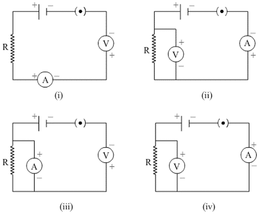 (a) (i)
(b) (ii)
(c) (iii)
(d) (iv)
Correct Answer is Option (b)
All the electrical components have been correctly connected in case (ii). This is because ammeter is connected in series and voltmeter is connected parallel to the resistor. Moreover, terminal of both the devices connected to positive terminal of the cell must be positive.
Q.6. What is the maximum resistance which can be made using five resistors each of 1/5 Ω?
(a) 1/5 Ω
(b) 10 Ω
(c) 5 Ω
(d) 1 Ω
Correct Answer is Option (d)
The maximum resistance is obtained when resistors are connected in series.
R =
= 5/5
= 1Ω
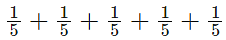
Q.7. What is the minimum resistance which can be made using five resistors each of 1/5 Ω?
(a) 1/5 Ω
(b) 1/25 Ω
(c) 1/10 Ω
(d) 25 Ω
Correct Answer is Option (b)
Minimum resistance is obtained when resistors are connected parallel
1/R = 5 + 5 + 5 +5 +5= 25 Ω
R = 1/25Ω
Q.8. The proper representation of the series combination of cells (Figure 12.4) obtaining maximum potential is
(a) (i)
(b) (ii)
(c) (iii)
(d) (iv)
Correct Answer is Option (a)
The positive terminal of a cell should be connected to the negative terminal of the adjacent cell. Case (i) represents the correct combination of cells.
Q.9. Which of the following represents voltage?
(a) 
(b) Work done × Charge
(c) 
(d) Work done × Charge × Time
Correct Answer is Option (a)
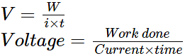
Potential difference (V) is defined as the ratio of work done (W) and charge (Q).
V = W/Q
Charge is defined as
where i = current
t = time
So,
Q.10. A cylindrical conductor of length l and uniform area of crosssection A has resistance R. Another conductor of length 2l and resistance R of the same material has an area of cross-section
(a) A/2
(b) 3A/2
(c) 2A
(d) 3A
Correct Answer is Option (c)
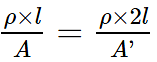
Let the resistivity of the material be ρ
Resistance (R) of the first cylindrical conductor = ρl/A
where l = length of conductor
A = area of cross-section
Now, another cylindrical conductor has double length but the same resistance. Let its area of cross-section be A'
Its resistance (R') will be
Since resistance is same
R = R'
Solving it, we get A' = 2A

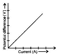
Q.11. A student carries out an experiment and plots the V-I graph of three samples of nichrome wire with resistances R1, R2, and R3 respectively (Figure.12.5). Which of the following is true?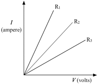 (a) R1 = R2 = R3
(b) R1 > R2 > R3
(c) R3 > R2 > R1
(d) R2 > R3 > R1
Correct Answer is Option (c)
Since the current (I) is plotted on y-axis and potential difference (V) is plotted on x-axis, so the slope of the graph is 1/R. It means higher the slope, the lesser is the resistance. So, R1 will be minimum and R3 will be maximum.
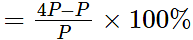
Q.12. If the current I through a resistor is increased by 100% (assume that temperature remains unchanged), the increase in power dissipated will be
(a) 100 %
(b) 200 %
(c) 300 %
(d) 400 %
Correct Answer is Option (c)
If the current is increased by 100% then the current will become twice i.e 2I. The power dissipated through a resistor is given by P = I2R
If the current is made twice then power dissipated will become four times.
The percentage increase in power is given as,
Increase in power
= 300%
Q.13. The resistivity does not change if
(a) The material is changed
(b) The temperature is changed
(c) The shape of the resistor is changed
(d) Both material and temperature are changed
Correct Answer is Option (c)
Resistivity of a material depends only on the temperature and the nature of material. Shape of the resistor has no effect on the resistivity.
Q.14. In an electrical circuit, three incandescent bulbs A, B, and C of rating 40 W, 60 W, and 100 W respectively are connected in parallel to an electric source. Which of the following is likely to happen regarding their brightness?
(a) Brightness of all the bulbs will be the same
(b) Brightness of bulb A will be the maximum
(c) Brightness of bulb B will be more than that of A
(d) Brightness of bulb C will be less than that of B
Correct Answer is Option (c)
Since all the three bulbs are connected in parallel so potential difference (V) across all the bulbs is same. Power dissipated is given by P=V2/R.
Lower the resistance, higher the power dissipation. Hence higher the brightness. Out of all the three bulbs, 100 W bulb will have minimum resistance because rated voltage of all the bulbs will be same and its power dissipation is maximum. Thus, 100 W will have maximum brightness and 40 W bulb will have minimum brightness.
Q.15. In an electrical circuit, two resistors of 2 Ω and 4 Ω respectively are connected in series to a 6 V battery. The heat dissipated by the 4 Ω resistor in 5 s will be
(a) 5 J
(b) 10 J
(c) 20 J
(d) 30 J
Correct Answer is Option (c)
Equivalent resistance of the circuit is R = 4 + 2 = 6Ω
current, I= V/R = 6/6= 1A
the heat dissipated by 4-ohm resistor is, H = I2Rt = 20J
Q.16. An electric kettle consumes 1 kW of electric power when operated at 220 V. A fuse wire of what rating must be used for it?
(a) 1 A
(b) 2 A
(c) 4 A
(d) 5 A
Correct Answer is Option (d)
Power (P) = 1 kW = 1000 W
Potential difference (V) = 220 V
We know,
P = VI
I = P/V
I = 1000/220
I = 4.54 A
From all the given options, 5 A fuse wire is correct
Q.17. Two resistors of resistance 2 Ω and 4 Ω when connected to a battery will have
(a) Same current flowing through them when connected in parallel
(b) Same current flowing through them when connected in series
(c) Same potential difference across them when connected in series
(d) Different potential differences across them when connected in parallel
Correct Answer is Option (b)
When two resistors are connected in series with a battery then-current passing through them is the same.
Q.18. Unit of electric power may also be expressed as
(a) Volt ampere
(b) Kilowatt-hour
(c) Watt second
(d) Joule second
Correct Answer is Option (a)
Power is defined as
P = VI
where, V = Potential difference (Volt)
I = Current (Ampere)
So, unit of electric power may also be expressed as volt-ampere.
Short Answer Questions
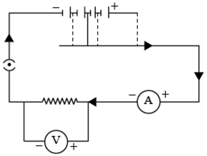
Q.19. A child has drawn the electric circuit to study Ohm’s law as shown in Figure. His teacher told that the circuit diagram needs correction. Study the circuit diagram and redraw it after making all corrections.
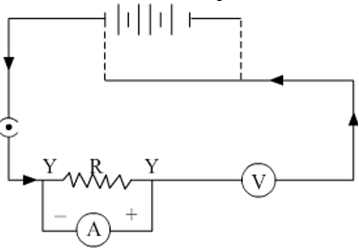
The correct circuit diagram is shown as below
Q.20. Three 2 Ω resistors, A, B, and C, are connected as shown in Figure. Each of them dissipates energy and can withstand a maximum power of 18W without melting. Find the maximum current that can flow through the three resistors?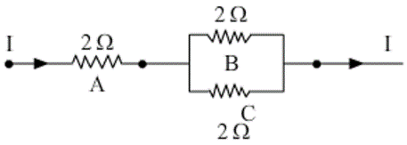
Current P= I2R
18W = I2 x 2Ω
I2 = 18W/ 2Ω
= 9
I = 3A
Maximum value of current passing through A is 3A.
Current through B = Current through C = 1/2 x Current through A
Current through B = Current through C = 1/2 x 3
Current through B = Current through C = 1.5 A
Q.21. Should the resistance of an ammeter be low or high? Give reason.
The resistance of an ammeter should ideally be zero so that it does not affect the flow of current in the circuit. Hence, the resistance of an ammeter should be very low as zero resistance is not possible in real life.
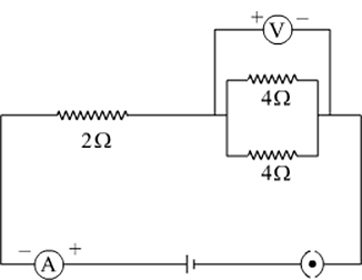
Q.22. Draw a circuit diagram of an electric circuit containing a cell, a key, an ammeter, a resistor of 2Ω in series with a combination of two resistors (4Ω each) in parallel and a voltmeter across the parallel combination. Will the potential difference across the 2Ω resistor be the same as that across the parallel combination of 4Ω resistors? Give reason.
Net resistance of two 4 Ω resistors connected in parallel is 2 Ω. Since we have two resistors of same resistance in series so the potential drop across each one of them will be same.
Q.23. How does use of a fuse wire protect electrical appliances?
Fuse wire has low melting point and high resistance. So, whenever there is surge in the electric current, the fuse wire melts and breaks the circuit. This prevents any damage to the electrical appliances. Thus, a fuse wire protects the electrical appliances.
Q.24. What is electrical resistivity? In a series electrical circuit comprising a resistor made up of a metallic wire, the ammeter reads 5 A. The reading of the ammeter decreases to half when the length of the wire is doubled. Why?
Property of the conductor which resists the flow of electric current is called resistivity. Resistance for a particular material is unique. Resistance is directly proportional to length of conductor and inversely proportional to current flow. When length is doubled resistance becomes double and current flow reduces to half. This is the reason for the decrease in ammeter reading.
Q.25. What is the commercial unit of electrical energy? Represent it in terms of joules.
Commercial unit of electrical energy is kilowatt/hr
1 kw/hr = 1 kW h
= 1000 W × 60 × 60s
= 3.6 × 10⁶ J
Q.26. A current of 1 ampere flows in a series circuit containing an electric lamp and a conductor of 5 Ω when connected to a 10 V battery. Calculate the resistance of the electric lamp. Now if a resistance of 10 Ω is connected in parallel with this series combination, what change (if any) in current flowing through the 5 Ω conductor and potential difference across the lamp will take place? Give reason.
1) Let R be the resistance of the electric lamp. In series total resistance = 5 + R
I = v/r
1 = 10/5+R
R = 5 ohm
2) V across Lamp + conductor = 10 V
V acoess Lamp = I × R = 1 * 5 = 5 Volt
Q.27. Why is parallel arrangement used in domestic wiring?
Parallel arrangement used in domestic wiring because it provides the same potential difference across each electrical appliance.
Q.28. B1, B2 and B3 are three identical bulbs connected as shown in Figure. When all the three bulbs glow, a current of 3A is recorded by the ammeter A.
(i) What happens to the glow of the other two bulbs when the bulb B1 gets fused?
(ii) What happens to the reading of A1, A2, A3, and A when the bulb B2 gets fused?
(iii) How much power is dissipated in the circuit when all the three bulbs glow together?
Since all the three bulbs are identical so current through each bulb will remain same i.e 1 A
(i) Even when bulb B1 gets fused, other two bulbs will continue to glow with same brightness because all the three bulbs are connected in parallel so potential difference across each bulb remains same.
(ii) When bulb B2 gets fused then the reading A2 will become zero. The reading of A1 and A3 will remain same as 1 A because potential difference across them remains same. However, the reading of A will decrease and will become 2 A.
(iii) Power dissipated by bulb B1 will be
P1 = VI
P1= 4.5 × 1
P1= 4.5 W
Similarly,
P2 = 4.5 W
P3 = 4.5 W
Hence total power dissipated by the circuit will be
Pnet = P1 + P2 + P3
Pnet = 4.5 + 4.5 + 4.5
Pnet =13.5 W
Long Answer Questions
Q.29. Three incandescent bulbs of 100 W each are connected in series in an electric circuit. In another circuit another set of three bulbs of the same wattage are connected in parallel to the same source.
(a) Will the bulb in the two circuits glow with the same brightness? Justify your answer.
(b) Now let one bulb in both the circuits get fused. Will the rest of the bulbs continue to glow in each circuit? Give reason.
(Resistance of the bulbs in series will be three times the resistance of single bulb. Hence, the current in the series combination will be one-third compared to current in each bulb in parallel combination. The parallel combination bulbs will glow more brightly.
The bulbs in series combination will stop glowing as the circuit is broken and current is zero. However the bulbs in parallel combination shall continue to glow with the same brightness.
Q.30. State Ohm’s law? How can it be verified experimentally? Does it hold good under all conditions? Comment.
Ohm’s law : When the physical conditions such as temperature etc. remain same, the current flowing through the conductor is directly proportional to the potential difference applied across the ends of the conductor, i.e.,
I ∝ V or V ∝ I
⇒ V/I = constant
⇒ V = IR
Where R is constant of proportionality and is called resistance of the wire.
Necessary condition for validity of Ohm’s law is that physical condition such as temperature of the conductor remains same.Procedure: Experiment to verify ohm's law
1. Connect the various components as
2. Close the sky, so that current begins to flow in the circuit.
3. Note down the potential difference (V) across the conductor PQ of resistance R shown by the voltmeter and the corresponding current (I) shown by the ammeter.
4. Now move the knob of rheostat so that the current in the circuit increases.
5. Again note down the potential difference (V) across the conductor R in the voltmeter and current in the circuit shown by ammeter.
6. Repeat the experiment five times by increasing the current in the circuit by moving the knob of the rheostat in steps
The value of V/I = R (constant) Plot a graph between V and I by taking V along X- axis along. We get a straight line passing through origin.
Conclusion :
- From the graph between V and I, we conclude that I = V, which is Ohm's law.
- Hence Ohm's law is verified experimentally.
- Ohm's law does not hold under all conditions.
- Ohm's law does not hold for non-ohmic material such as electrotyte.

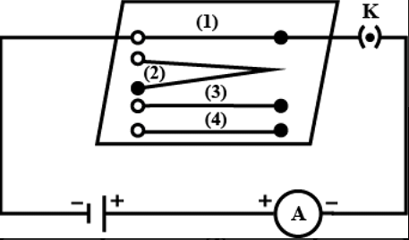
Q.31. What is electrical resistivity of a material? What is its unit? Describe an experiment to study the factors on which the resistance of conducting wire depends.
Electrical resistivity is the inherent property of a conductor due to which it opposes the flow of current in the wire. It does not depend on the length and area of cross section of wire. It depends only on the temperature and nature of the material of the wire.
Its SI unit is Ωm (Ohm metre).
Experiment to study the factors on which the resistance of conducting wire depends:
Materials needed: nichrome wires and copper wires of specified dimensions as described below, an ammeter, a cell, a key etc.,
Procedure: 1. Set up an electric circuit consisting of a cell, an ammeter, a nichrome wire of length l [say, marked (1)] and a plug key, as shown in the diagram.
2. Now, plug the key. Note the current in the ammeter.
3. Replace the nichrome wire with another nichrome wire of the same thickness but twice the length, that is 2l [marked (2)]. Note the ammeter reading.4. Now replace the wire with a thicker nichrome wire of larger cross-sectional area and of the same length l [marked (3)]. Again note down the current through the circuit.
5. Now instead of taking a nichrome wire, connect a copper wire [marked (4) ] in the circuit. Let the wire be of the same length and same area of cross-section as that of the first nichrome wire [marked (1)]. Note the value of the current. Notice the difference in the current in all cases.
6. Tabulate all the readings and calculate the resistance from the ratio of potential difference V and current I.
It is observed that the resistance of the wire increases with the increase in length of the nichrome wire and decreases with the increase in the area of cross-section.If we replace the nichrome wire with copper wire of the same length and area of cross-section even then resistance will be different.These observations show that the resistance of a wire depends on the length, area of cross-section and nature of the material.
 It is observed that the resistance of the wire increases with the increase in length of the nichrome wire and decreases with the increase in the area of cross-section.If we replace the nichrome wire with copper wire of the same length and area of cross-section even then resistance will be different.These observations show that the resistance of a wire depends on the length, area of cross-section and nature of the material.
 Q.32. How will you infer with the help of an experiment that the same current flows through every part of the circuit containing three resistances in series connected to a battery?
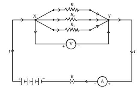
Connect an ammeter in the circuit and three voltmeter across each resistance as shown in figure. Note the reading of ammeter let us say it is:
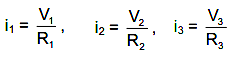
(i). Note the reading of voltmeters let us say they are V1, V2 and V3 respectively across R1, R2 and R3. Now by ohm’s law
We will find that i1 = i2 = i3 = i.
Hence same current flows through every part of the circuit.
Q.33. How will you conclude that the same potential difference (voltage) exists across three resistors connected in a parallel arrangement to a battery?
Take three resistors R1, R2 and R3, connect them in parallel to make a circuit; as shown in the figure.
Use voltmeter to take reading of potential difference of three resistors in parallel combination.
Now, remove the resistor R1 and take the reacting of the potential difference of remaining resistors combination.
Then, remove the resistor R2, and take the reading of potential difference of remaining resistor.Observation: In each case Voltmeter reading was the same which shows that the same potential difference exists across three resistors connected in a parallel arrangement.
Q.34. What is Joule’s heating effect? How can it be demonstrated experimentally? List its four applications in daily life.
The heating effect of current is defined by Joules law of heating. It is also called ohmic heating and resistive heating. In a conductor when an electric field is applied across its ends, the free electrons available in it start drifting opposite to the direction of the electric field. These electrons collide with the atoms which have lost the electrons. As a result of these collisions, some energy of the electrons is transferred to the atoms which vibrate violently as they gain energy. Thus, heat is developed in the conductor. Greater the current, greater will be the rate of collision and so greater will be the heat produced.
Joule's heating effect:
According to Joule's law of heating, the heat produced in a wire is directly proportional to
(a) Square of current (I2)
(b) Resistance of wire (R)
(c) Time (t), for which current is passed.
i.e., Heat producted, H = I2 R t Joules.
Applications of Joule's heating effect in daily life :
(a) The heating effect of current is utilised in the working of electric heating appliances such as electric iron, electric kettle, electric toaster, electric oven, room heaters, geysers, etc.
(b) The heating effect of electric current is utilised in electric bulbs.
(c) The heating effect of electric current is utilised in electric fuse for protecting household wiring and electrical appliances.
Q.35. Find out the following in the electric circuit given in Figure
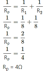
(a) Effective resistance of two 8 Ω resistors in the combination
(b) Current flowing through 4 Ω resistor
(c) Potential difference across 4 Ω resistance
(d) Power dissipated in 4 Ω resistor
(e) Difference in ammeter readings, if any.
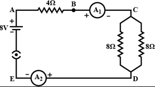
(a) Both 8Ω resistors are connected in parallel so the effective resistance of the two will be
(b) Net resistance of the circuit will be
Rnet = 4 + 4
Rnet = 8Ω
So, current in 4Ω resistor using Ohm's law is
I = 1 A
(c) Potential difference across 4Ω resistor is
V = IR
V = 1 × 4
V = 4 V
(d) Power dissipated through 4Ω is
P = i2R
P = 12 × 4
P = 4 W
(e) Both ammeters A1 and A2 will record same readings because they are connected in series. Hence difference in their readings will be zero.
|
85 videos|437 docs|75 tests
|
FAQs on NCERT Exemplar: Electricity - Science Class 10
| 1. What is electricity? |  |
| 2. How is electricity generated? | |
| 3. What are conductors and insulators of electricity? | |
| 4. What is the difference between series and parallel circuits? | |
| 5. How does a circuit breaker work? | |

|
2.5K Views |

|
4.64/5 Rating |

|
Dec 23, 2024 Last updated |

|
Explore Courses for Class 10 exam
|
|
NCERT Exemplar: Electricity | Science Class 10
,Sample Paper
,NCERT Exemplar: Electricity | Science Class 10
,Summary
,NCERT Exemplar: Electricity | Science Class 10
,past year papers
,Free
,Semester Notes
,mock tests for examination
,shortcuts and tricks
,Important questions
,practice quizzes
,Exam
,Viva Questions
,Objective type Questions
,ppt
,video lectures
,MCQs
,Extra Questions
,Previous Year Questions with Solutions
,study material
;


NCERT Exemplar: Electricity Free PDF Download
Importance of NCERT Exemplar: Electricity
NCERT Exemplar: Electricity Notes
NCERT Exemplar: Electricity Class 10 Questions
Study NCERT Exemplar: Electricity on the App
|
© EduRev
|
Education Revolution
|


|


