Flumes, Irrigation Engineering | Irrigation Engineering Notes - Agricultural Engineering PDF Download

Parshall Flume
Parshall flumes are devices for the measurement of flow of water in open channels when depth of flow is less i.e., head drop is very small, the volume of flow is less and channel bed slope is less. The flume consists a converging section with a level floor and walls converges towards the throat section, a throat section with a downward sloping floor and parallel walls, and a diverging section with an upward sloping floor and diverging walls towards the outlet. The size of flume is determined by the width of its throat. The size ranges from 7.5 cm to several metres in throat width.
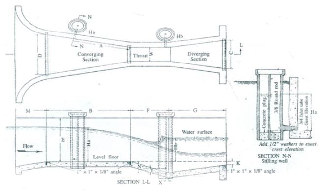
Fig. 7.1.Parshall flume.
Parshall flumes are available in various sizes. Care must be taken whileconstructing the flumes exactly in accordance with structural dimensions.
On the basis of the throat width, Parshall flumes have been classified into three main groups.
- Very small - 25.4 mm to 76.2 mm.
- Small 152.40 mm to 2438.4 mm.
- Large 3048 mm to 15240 mm.
Standard dimensions of Parshall flumes with discharge values are presented in Table 7.1 and 7.2, respectively. Discharge through the flume can occur under either free or submerged flow condition. Flow is submerged when the down-stream water elevation retards the rate of discharge. To determine discharge through the flume under free flow condition, head is measured at upstream section (Ha).However, downstream head (Hb) is also measured for submerged flow condition. Free flow condition prevails if the submergence ratio (Hb/Ha) remains within 0.5, 0.6 and 0.7 for width of throat varying from 2.5 to 7.5 cm, 1.5 to 22.5 cm and 3.0 to 24.0 cm, respectively.
Table 7.1.Dimensions and capacities of Parshall flume of various sizes (Letter, refer Fig. 7.2)
Throat width | A | B | C | D | E | F | G | K | N | X | Y | Free-flow capacity | |
cm | cm | cm | cm | cm | cm | cm | cm | cm | cm | cm | cm | Minimum, L s-1 | Maximum, L s-1 |
7.5 | 31 | 46 | 18 | 26 | 46 | 15 | 30.5 | 2.5 | 5.7 | 2.5 | 3.8 | 0.85 | 28.4 |
15 | 41.4 | 61 | 39 | 39.7 | 61 | 30.5 | 61 | 7.6 | 12 | 5.1 | 7.6 | 1.4 | 110.8 |
23 | 58.8 | 86 | 38 | 57.5 | 76 | 30.5 | 45.5 | 7.6 | 12 | 5.1 | 7.6 | 2.5 | 253 |
30 | 91.5 | 134 | 61 | 84.5 | 92 | 61 | 91.5 | 7.6 | 23 | 5.1 | 7.6 | 3.13 | 456.6 |
Table 7.2.Free flow discharge values for Parshall Flume
Discharge, L s-1 | ||||
Head | Throat width | |||
cm | 7.5 cm | 15 cm | 23 cm | 30 cm |
3 | 0.8 | 1.4 | 2.6 | 3.1 |
4 | 1.2 | 2.3 | 4 | 4.5 |
5 | 1.7 | 3.3 | 5.5 | 7 |
6 | 2.3 | 4.4 | 7.2 | 9.6 |
7 | 2.7 | 5.4 | 8.5 | 11.4 |
8 | 3.4 | 7.2 | 11.1 | 14.4 |
9 | 4.3 | 8.5 | 13.5 | 17.7 |
10 | 5 | 10.2 | 15.9 | 21.1 |
11 | 5.8 | 11.6 | 18.1 | 23.8 |
12 | 6.7 | 13.5 | 21.1 | 27.5 |
13 | 7.5 | 15 | 23.3 | 31 |
14 | 8.5 | 17.3 | 26.7 | 35 |
15 | 9.4 | 19.2 | 29.5 | 38.7 |
16 | 10.4 | 21.2 | 32.5 | 42.7 |
17 | 11.4 | 23.2 | 35.6 | 46.6 |
18 | 12.4 | 25.3 | 39 | 51.2 |
19 | 13.6 | 27.8 | 42.5 | 55 |
20 | 14.3 | 30 | 45.8 | 59.7 |
21 | 15.8 | 32.7 | 49.3 | 64.7 |
22 | 17.1 | 35.2 | 53.3 | 69.8 |
23 | 18.2 | 37.7 | 56.8 | 74 |
24 | 19.4 | 40.1 | 60.5 | 79 |
25 | 20.7 | 42.7 | 64.5 | 84.1 |
26 | 22 | 45.7 | 69.3 | 89 |
27 | 23.3 | 48.1 | 72.4 | 94.3 |
28 | 24.8 | 51.5 | 76.7 | 100 |
29 | 26 | 54 | 80.7 | 105.1 |
30 | 27.5 | 57.3 | 85.2 | 111 |
The discharge is measured by the following formula:
 ........(7.1)
Where, Q is the discharge; C, n are the flume coefficients which vary with the size of the flume and H is the measuring head.
Table 7.3 gives a set of standard values for the C,n for different dimensions (these co-efficient are in fps units so the calculated discharge would be in ft3/s and head has to be in ft,)
Table 7.3. Value of C and n for different throat widths
Throat width | Coefficient (C) | Exponent (n) |
1 in | 0.338 | 1.55 |
2 in | 0.676 | 1.55 |
3 in | 0.992 | 1.55 |
6 in | 2.06 | 1.58 |
9 in | 3.07 | 1.53 |
1 ft | 3.95 | 1.55 |
2 ft | 8.00 | 1.55 |
3 ft | 12.00 | 1.57 |
4 ft | 16.00 | 1.58 |
5 ft | 20.00 | 1.59 |
6 ft | 24.00 | 1.59 |
7 ft | 28.00 | 1.60 |
8 ft | 32.00 | 1.61 |
10 ft | 39.38 | 1.60 |
12 ft | 46.75 | 1.60 |
15 ft | 57.81 | 1.60 |
20 ft | 76.25 | 1.60 |
25 ft | 94.69 | 1.60 |
30 ft | 113.13 | 1.60 |
40 ft | 150.00 | 1.60 |
50 ft | 186.88 | 1.60 |
In the above Fig., Ha is upstream head and Hb is downstream head.
Advantages
(a) This instrument is effective when the total head drop is small.
(b) Its operation is independent of approaching velocity.
(c) Being a self-cleaning device, it is not affected by sand or silt deposition.
7.2 Cut-throat Flume
The geometry of the throat-less flumes with broken plane transition was first developedin Punjab by Harvey in 1912. In the cut throat flume however, theflume discharge and the modular limit are related to the piezometric heads at two pointsin the converging section (ha) and in the downstream expansion (hb). One of theadvantages of a cut- throat measuring flumes is that there areonly two walls on each side, resulting in an economic installation. The cross-section canbe rectangular, trapezoidal or triangular, depending only on the availability of appropriate calibration. A U- shaped section can also be used for critical depth flumes.
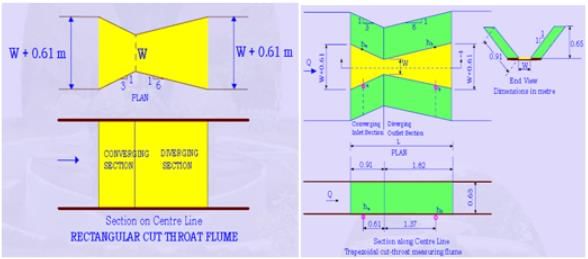
Fig. 7.2.Cut-throat flume.
Design specifications of a cut-throat flume
L = Total length of the flume,
L1= Converging section = L/3
L2=Diverging section= 2L/3,
La=Distance to piezometer tap a = 2L/9
Lb=Distance to piezometer tap b= 5L/9
B=width of the converging and diverging section= W + L/4.5
The cut-throat flume can operate either as a free flow or a submerged flow structure. Under free flow conditions, critical depth occurs in the vicinity of minimum width, w, which is called the flume throat or the flume neck. The attainment of critical depth makes it possible to determine the flow rate, knowing only an upstream depth, ha. The relationship between flow rate Q and upstream depth of flow ha, in a cut-throat flume under free flow conditions is given by the following experimental relationship:
Q = C1 han L (7.2)
In which,
Q = flow rate
C1= free flow coefficient, which is the value of Q when ha is 1.0 foot.
n = exponent, whose value depends only on the flume length L.
FAQs on Flumes, Irrigation Engineering - Irrigation Engineering Notes - Agricultural Engineering
| 1. What is a flume in irrigation engineering? |  |
| 2. How does a flume work in agricultural engineering? | |
| 3. What are the benefits of using flumes in irrigation? | |
| 4. How are flumes constructed in agricultural engineering? | |
| 5. What are the challenges in designing and implementing flumes for irrigation systems? | |


Flumes
,ppt
,Previous Year Questions with Solutions
,Important questions
,Semester Notes
,mock tests for examination
,Exam
,Irrigation Engineering | Irrigation Engineering Notes - Agricultural Engineering
,Extra Questions
,shortcuts and tricks
,Summary
,Sample Paper
,MCQs
,past year papers
,practice quizzes
,video lectures
,Irrigation Engineering | Irrigation Engineering Notes - Agricultural Engineering
,Viva Questions
,Flumes
,Objective type Questions
,Flumes
,Free
,Irrigation Engineering | Irrigation Engineering Notes - Agricultural Engineering
,study material
;


Flumes, Irrigation Engineering Free PDF Download
Importance of Flumes, Irrigation Engineering
Flumes, Irrigation Engineering Notes
Flumes, Irrigation Engineering Agricultural Engineering Questions
Study Flumes, Irrigation Engineering on the App
|
© EduRev
|
Education Revolution
|


|


