Study Notes: DC Machines - 1 | Electrical Machines for Electrical Engg. - Electrical Engineering (EE) PDF Download
DC machine is a highly versatile and flexible machine.
It can satisfy the demands of load requiring high starting, accelerating and retarding torques.
If the conversion is from mechanical to electrical energy, the machine is called as Generator.
If the conversion is from electrical to mechanical energy, the machine is called as Motor.
To understand, design and use these machines the following laws must be studied.
- Electric circuit laws - Kirchoff′s Laws
- Magnetic circuit law - Ampere′s Law
- Law of electromagnetic induction - Faraday′s Law
- Law of electromagnetic interaction -BiotSavart′s Law
Most of the present day machines have one or two electric circuits linking a common magnetic circuit. In subsequent discussions the knowledge of electric and magnetic circuit laws is assumed. The attention is focused on the Faraday’s law and Biot Savart’s law in the present study of the electrical machines.
Application of Faraday's law according to electro mechanical energy conversion results in the generation of both transformer and rotational emf to be present in the coil moving under a changing field. This principle is utilized in the induction machines and a.c. commutator machines. The direction of the induced emf is decided next. This can be obtained by the application of the Lenz’s law and the law of interaction.
Law of induction-Generator action
Law For Motoring Action
Armature Reaction in DC Motor
The effect of magnetic field set up by armature current on the distribution of flux under main poles of a generator. The armature magnetic field has two effects:
(i) It Demagnetizes or weakens the main flux and
(ii) It cross-magnetises or distorts it.
- Armature reaction in motors for a given polarity of the field and sense of rotation, the motoring and generating modes differ only in the direction of the armature current. Alternatively, for a given sense of armature current, the direction of rotation would be opposite for the two modes. The leading and trailing edges of the poles change positions if direction of rotation is made opposite. Similarly when the brush leads are considered, a forward lead given to a generator gives rise to weakening of the generator field but strengthens the motor field and vice-versa. Hence it is highly desirable, even in the case of non-reversing drives, to keep the brush position at the geometrical neutral axis if the machine goes through both motoring and generating modes.
- The second effect of the armature reaction in the case of motors as well as generators is that the induced emf in the coils under the pole tips get increased when a pole tip has higher flux density. This increases the stress on the ‘mica’ (micanite) insulation used for the commutator, thus resulting in increased chance of breakdown of these insulating sheets. To avoid this effect the flux density distribution under the poles must be prevented from getting distorted and peaky.
- The third effect of the armature reaction mmf distorting the flux density is that the armature teeth experience a heavy degree of saturation in this region. This increases the iron losses occurring in the armature in that region.The increase in iron loss could be as high as 50 percent more at full load compared to its no-load value.
Commutation
- The currents induced in armature conductors of a d.c. generator are alternating. These currents flow in one direction when armature conductors are under N-pole and in the opposite direction when they are under S-pole.
- As conductors pass out of the influence of a N-pole and enter that of S-pole, the current in them is reversed. This reversal of current takes place along magnetic neutral axis or brush axis i.e. when the brush spans and hence short circuits that particular coil undergoing reversal of current through it.
- This process by which current in the short-circuited coil is reversed while it crosses the M.N.A. is called commutation. The brief period during which coil remains short-circuited is known as commutation period Tc.
- If the current reversal i.e.the change from +I to zero and then to −I is completed by the end of short circuit or commutation period, then the commutation is ideal. If current reversal is not complete by that time, then sparking is produced between the brush and the commutator which results in progressive damage to both.
- The brush width is equal to the width of one commutator segment and one mica insulation.
Types of DC Machines:
- The types of DC machine depends upon the excitation of DC machine.
- The production of magnetic flux in the machine by circulating current in the field winding is called excitation.
- DC Machines can be classified according to the electrical connections of the armature winding and the field windings.
There are two methods of excitation namely, separate excitation and self-excitation.
In separate excitation, the field coils are energised by a separate DC source. The terminals of the winding can be connected across the input voltage terminals or fed from a separate voltage source.
In self-excitation,the current flowing through the field winding is supplied by the machine itself. The field winding can be connected either in series or in parallel with the armature winding
Speed Control of DC Motors
Speed of a DC motor can be varied by varying flux, armature resistance or applied voltage. Different speed control methods for different DC shunt and series methods are there.
Or
Speed Control of Shunt Motors:
- Flux control method
- Armature and Rheostatic control method
- Voltage control method
1. Multiple voltage control
2. Ward Leonard system
Speed Control of Series Motors:
- Flux control method
1. Field diverter
2. Armature diverter
3. Trapped field control
4. Paralleling field coils - Variable Resistance in series with motor
- Series -parallel control method
Speed Control Methods
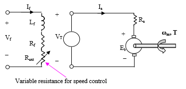
Flux Control Method:
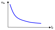
- In this flux control method, speed of the motor is inversely proportional to the flux. Thus, by decreasing flux and speed can be increased vice versa.
- To control the flux , he rheostat is added in series with the field winding will increase the speed (N), because of this flux will decrease.
- The field current is relatively small and hence I2R loss is decreased. This method is quite efficient.
In this method of speed control, Ra and VT remain fixed.

Therefore, from equation
ωm α 1/φ
Assuming magnetic linearity, φ α If
Or,
ωm α 1/If
i.e., Speed can be controlled by varying field current If.
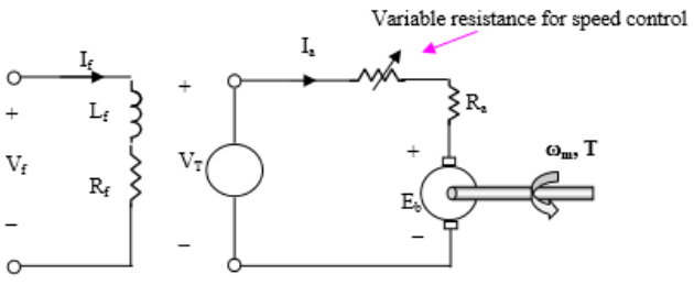
Armature Control Method:
- In the armature control method, the speed of the DC motor is directly proportional to the back emf (Eb) and Eb = V- IaRa.
- When supply voltage (V) and armature resistance Ra are kept constant, the Speed is directly proportional to armature current (Ia).
- If we add resistance in series with the armature, the armature current (Ia) decreases and hence speed decreases.

From speed-torque characteristics equation,we know that
For a load of constant torque, if VT and φ are kept constant, as the armature resistance Ra is increased, speed decreases. As the actual resistance of the armature winding is fixed for a given motor, the overall resistance in the armature circuit can be increased by inserting an additional variable resistance in series with the armature.
Voltage control method:
- Multiple voltage control: In this method shunt field of motor is connected to a fixed exciting voltage, but the armature is supplied with different voltages by connecting it across one of the several voltages with the help of a switch. The intermediate speeds can be obtained by adjusting the field regulator. This method is very rarely used.
- Ward-Leonard system: This system is used where very large variation in speed is required. In this method axillary machines along with DC motor whose speed is to be varied. The motor is supplied by a generator which is driven by a motor. Very sensitive and smooth speed control can be obtained by this system. Thus this method can be used in colliery winders, electric excavators, elevators and the main drives in steel mills.
This method is usually applicable to separately excited DC motors. In this method of speed control, Ra and Vt are kept constant.
In normal operation, the drop across the armature resistance is small compared to Eb and therefore: Eb α Vt
Since, Eb = KΦω
ωm is the Angular speed can be expressed as:
ωm = Vt/KΦ
- If flux is kept constant, the speed changes linearly with VT.
- As the terminal voltage is increased, the speed increases and vice versa.
|
35 videos|85 docs|42 tests
|
FAQs on Study Notes: DC Machines - 1 - Electrical Machines for Electrical Engg. - Electrical Engineering (EE)
| 1. What is a DC machine? |  |
| 2. How does a DC machine work? |  |
| 3. What are the main components of a DC machine? |  |
| 4. What are the advantages of DC machines? |  |
| 5. What are the applications of DC machines? |  |


