Past Year Questions: Deflection of Beams | Solid Mechanics - Mechanical Engineering PDF Download

Q1: For the 6m long horizontal cantilever beam PQR shown in the figure. Q is the mid-point. Segment PQ of the beam has flexural rigidity EI = 2 × 10⁵ kN,m2 whereas the segment QR has infinite flexural rigidity. Segment QR is subjected to uniformly distributed, vertically downward load of 5 kN/m. [2024, Set-II]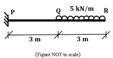
The magnitude of the vertical displacement (in mm) at point Q is _____ (rounded off to 3 decimal places)
Ans: 1.176 to 1.186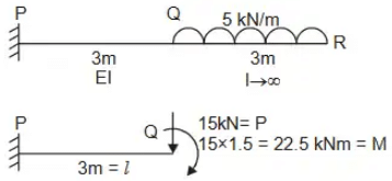 Vertical deflection at
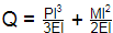
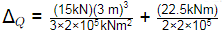
ΔQ = 6.75 × 10⁻⁴ + 5.0625 × 10⁻⁴m
ΔQ = 1.181 mm
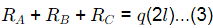
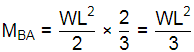
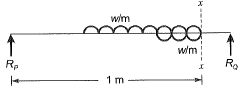
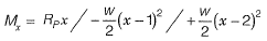
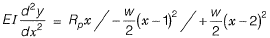
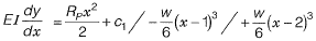
Q2: The beam shown in the figure is subjected to a uniformly distributed downward load of intensity q q between supports A and B. [2024, Set-I]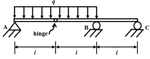 Considering the upward reactions as positive, the support reactions are
(a) RA = ql/2 ; RB = ql ; RC = ql/2
(b) RA = ql/2 ; RB = 5ql/2 ; RC = 0
(c) RA = -ql ; RB = 5ql/2 ; RC = ql/2
(d) RA = ql/2 ; RB = 5ql/2 ; RC = -ql
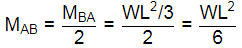
Ans: (d)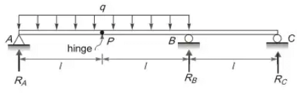 BMP = 0
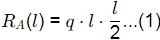
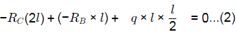
From 1, 2 and 3
RA = ql/2 ; RB = 5ql/2 ; RC = -ql
Q3: For the frame shown in the figure (not to scale), all members (AB, BC, CD, GB, and CH) have the same length, L and flexural rigidity, El. The joints at B and C are rigid joints, and the supports A and D are fixed supports. Beams GB and CH carry uniformly distributed loads of w per unit length. The magnitude of the moment reaction at A is wL2/k. What is the value of k k (in integer) ? ____ [2023, Set-II]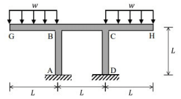 (a) 4
(a) 4
(b) 6
(c) 8
(d) 10
Ans: (b)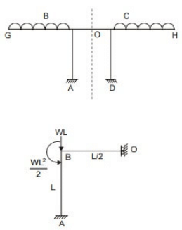 Due to symmetry, slope at mid of BC is zero and can be taken as slider at point O
Distribution factors: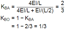
∴ 
∴ K = 6
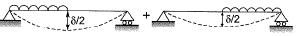
Q4: When a simply-supported elastic beam of span L and flexural rigidity EI(E is the modulus of elasticity and I I is the moment of inertia of the section) is loaded with a uniformly distributed load w per unit length, the deflection at the mid-span is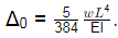
If the load on one half of the span is now removed, the mid-span deflection ____ [2023, Set-II]
(a) reduces to Δ0/2
(b) reduces to a value less than Δ0/2
(c) reduces to a value greater than Δ0/2
(d) remains unchanged at Δ0
Ans: (a)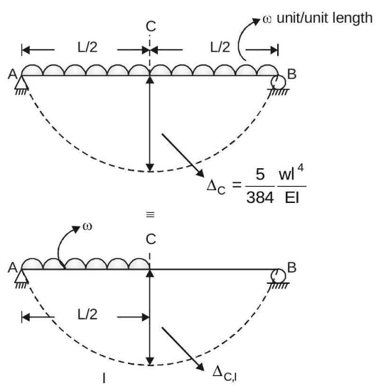
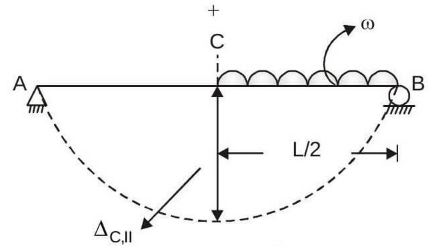 As Case-I and II are mirror image of each other,.
Hence, ΔC,1 = ΔC,II
Also, ΔC = ΔC,1 + ΔC,1
⇒ ΔC,I = ΔC,II = ΔC/2
Q5: A single story building model is shown in the figure. The rigid bar of mass 'm' is supported by three massless elastic columns whose ends are fixed against rotation. For each of the columns, the applied lateral force (P) and corresponding moment (M) are also shown in the figure. The lateral deflection (δ) of the bar is given by δ= PL3/12EI , where L is the effective length of the column, E is the Young's modulus of elasticity and I is the area moment of inertia of the column cross-section with respect to its neutral axis. [2021, Set-II]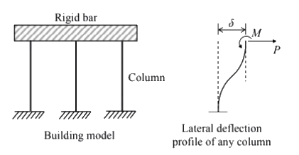 For the lateral deflection profile of the columns as shown in the figure, the natural frequency of the system for horizontal oscillation is
(a)
(b)
(c)
(d)
Ans: (a)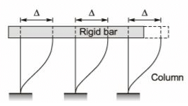
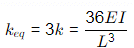
As the deflection will be same in all the 3 columns, so it represents a parallel connection.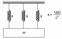 keq = 3k = 36EI/L3
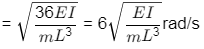
Natural frequency 
Q6: The equation of deformation is derived to be y = x2 − xL for a beam shown in the figure. [2021, Set-I]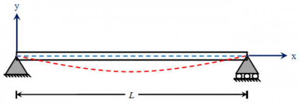
The curvature of the beam at the mid-span (in units, in integer) will be ______________ [2020, Set-I]
(a) 1
(b) 2
(c) 3
(d) 4
Ans: (b)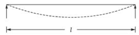 Given, y = x2 − xL
1/R = d2y/dx2
Curvature at mid section is dy/dx = 2x - 1
d2y/dx2 = 2
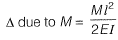
Q7: A cantilever beam PQ of uniform flexural rigidity (EI) is subjected to a concentrated moment M at R as shown in the figure.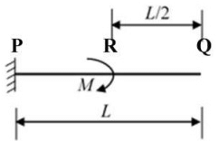 The deflection at the free end Q is
(a) M L2/6EI
(b) M L2/4EI
(c) 3M L2/8EI
(d) 3M L2/4EI
Ans: (c)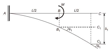
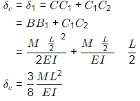
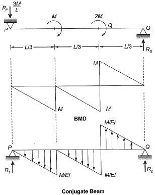
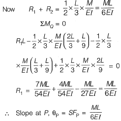
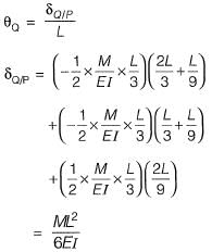
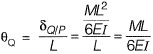
Q8: The figure shows a simply supported beam PQ of uniform flexural rigidity El carrying two moments M and 2M The slope at P will be [2018 : 2 Marks, Set-I]
(a) 0
(b) ML/(9EI)
(c) ML/(6EI)
(d) ML/(3EI)
Ans: (c)
Method-l
Method-ll
Moment area method:
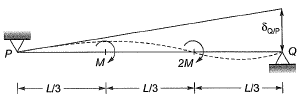
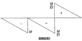
δQ/P = Defleciton of point Q wrt to tangent at point P
Q9: Two prismatic beams having the same flexural rigidity of 1000 kN-m2 are shown in the figures.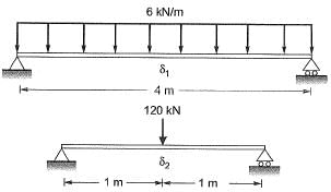 If the mid-span deflections of these beams are denoted by δ1 and δ2 (as indicated in the figures), the correct option is [2017 : 2 Marks, Set-II]
(a) δ1 = δ2
(b) δ1 < δ2
(c) δ1 > δ2
(d) δ1 >> δ2
Ans: (a)
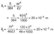
∴ δ1 = δ2
Q10: Two beams PQ (fixed at P with a roller support at Q, as shown in Figure I, which allows vertical movement) and XZ(with a hinge at Y) are shown in the Figures I and II respectively. The spans of PQ and XZ are L and 2L respectively. Both the beams are under the action of uniformly distributed load (w) and have the same flexural stiffness, EI (where, E and I respectively denote modulus of elasticity and moment of inertia about axis of bending). Let the maximum deflection and maximum rotation be δmax1 and δmax1, respectively, in the case of beam PQ and the corresponding quantities for the beam XZ be δmax2 and δmax2, respectively.
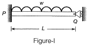
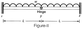 Which one of the following relationship is true? [2016 : 2 Marks, Set-I]
(a)
(b) 
(c) 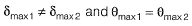
(d) 
Ans: (d)
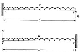
Deflection in beam xy at y = Deflection in beam yz at y
⇒ 
∴ R = 0
In beam PQ also at support Q, vertical reaction in zero because of roller support.
So, beam PQ, xyand yz are same.
∴ 
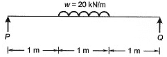
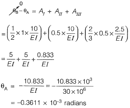
Q11: A 3 m long simply supported beam of uniform cross -section is subjected to a uniformly distributed load of w= 20 kN/m in the central 1 m as shown in the figure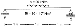 If the flexural rigidity (El) of the beam is 30 x 106 N-m2, the maximum slope (expressed in radians) of the deformed beam is [2016 : 2 Marks, Set-I]
(a) 0.681 x 10⁻⁷
(b) 0.361 x 10⁻³
(c) 4.310 x 10⁻⁷
(d) 5.910 x 10⁻⁷
Ans: (b)
Method-1
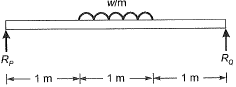
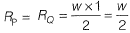
Due to symmetrical loading,
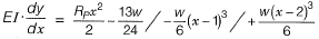
According to Macaulay method,
After integrating once
Due to symmetrical loading slope will be zero at mid section (x = 1.5 m),
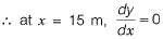
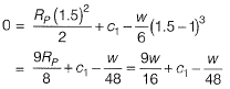
∴ 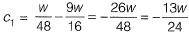
∴ Equation of slope,
The slope will be maximum at the support,
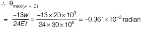
Method-ll
Moment Area Method,
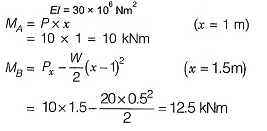
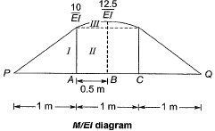
 Area of M/El diagram between points P and B.
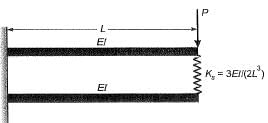
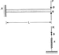
Q12: Two beams are connected by a linear spring as shown in the following figure. For a load P as shown in the figure, the percentage of the applied load P carried by the spring is_____. [2015 : 2 Marks, Set-I]
Ans:
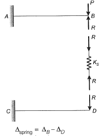
Compression of spring
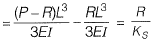
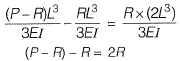

% force carried by spring = 25%
Q13: A steel strip of length, L = 200 mm is fixed at end A and rests at 6 on a vertical spring of stiffness, k = 2 N/mm. The steel strip is 5 mm wide and 10 mm thick. A vertical load, P= 50 N is applied at 6, as shown in the figure. Considering E = 200 GPa, the force (in N) developed in the spring is ________ . [2015 : 2 Marks, Set-II]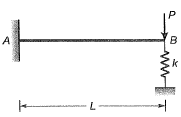 Ans:
Ans:
Deflection of point B = Deflection of spring
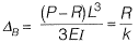
Where, R= Force in the spring,
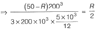
0.064(50 - R) = R
3.2= R+ 0.064 R
R = 3.0075 N
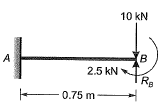
Q14: A horizontal beam ABC is loaded as shown in the figure below. The distance of the point of contraflexure from end A (in m) is _______ . [2015 : 1 Mark, Set-II]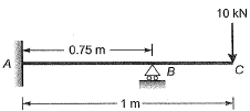
Ans:
Reaction at B,
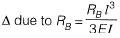
ΔB = 0 (Compatibility condition)
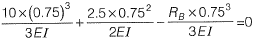

∴ RB = 15 kN
BM at a distance x from free end,
 BMx = 10 * x - 15 x (x - 0,25)= 0
⇒ 10x = 15x-3.75
⇒ 5x = 3.75
∴ x = 0.75m
∴ From end A, distance is 0.25 m.
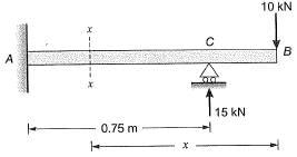
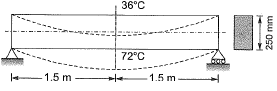
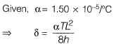
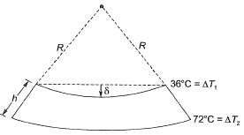
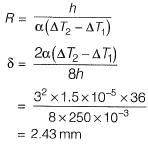
Q15: The beam of an overall depth 250 mm (shown below) is used in a building subjected to two different thermal environments. The temperatures at the top and bottom surfaces of the beam are 360C and 720C respectively. Considering coefficient of thermal expansion (α) as 1.50 x 10⁻⁵ per 0C, the vertical deflection of the beam (in mm) at its midspan due to temperature gradient is _______ . [2014 : 2 Marks, Set-II]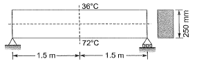 Ans:
Ans:
Method-I
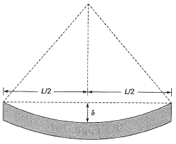

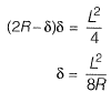
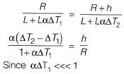
From properties of circle,
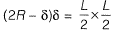
(Considering ‘δ’ very small so neglect δ2)
⇒ 
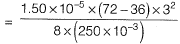
= 2.43
Method-ll
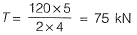
Q16: The tension (in kN) in a 10m long cable, shown in the figure, neglecting its self-weight is [2014 : 2 Marks, Set-II]
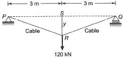
(a) 120
(b) 75
(c) 60
(d) 45
Ans: (b)
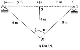
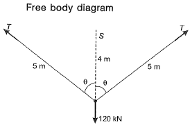

⇒ 2T cosθ = 120 ...(i)
Here,


⇒ 
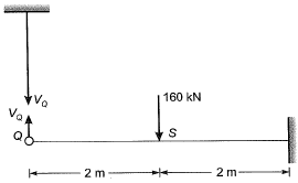
Q17: The axial load (in kN) in the member PQ for the arrangement/assembly shown in the figure given below is _________. [2014 : 2 Marks, Set-II]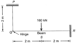 Ans:
Ans:
Free body diagram,
For principle of superposition,
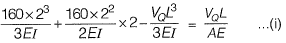
Deflections due to axial forces will be very less as compared to bending forces.
So we can neglect the axial deformation.
∴ From equation (i),
⇒ VQ = 50 kN
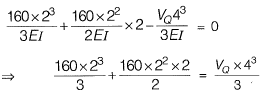
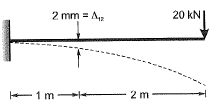
Q18: For the cantilever beam of span 3 m (shown below), a concentrated load of 20 kN applied at the free end causes a vertical displacement of 2 mm at a section located at a distance of 1 m from the fixed end. If a concentrated vertically downward load of 10 kN is applied at the section located at a distance of 1 m from the fixed end (with no other load on the beam), the maximum vertical displacement in the same beam (in mm) is ____. [2014 : 2 Marks, Set-I]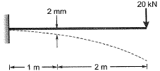 Ans:
Ans:
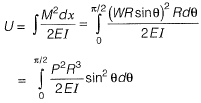
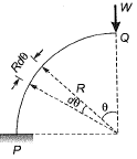
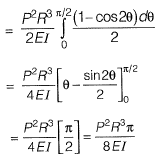
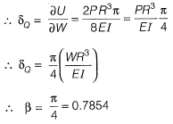
Q19: A uniform beam (EI= constant) PQ in the form of a quarter circle of radius R is fixed at end P and free at the end Q, where a load H/is applied as shown. The vertical downward displacement δQ at the loaded point Q is given by  Find the value of β correct to 4-decimal place. [2013 : 2 Marks]
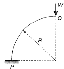 Ans:
Ans:
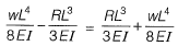
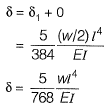
Q20: A simply supported beam is subjected to a uniformly distributed load of intensity w per unit length, on half of the span from one end. The length of the span and the flexural stiffness are denoted as I and EI respectively. The deflection at mid-span of the beam is [2012 : 2 Marks]


Ans:
Method-I
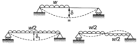
Method-ll
Total deflection
|
33 videos|72 docs|29 tests
|
FAQs on Past Year Questions: Deflection of Beams - Solid Mechanics - Mechanical Engineering
| 1. What is beam deflection and why is it important in engineering? |  |
| 2. What are the common methods used to calculate beam deflection? | |
| 3. How does the type of beam support influence deflection? | |
| 4. What factors affect the deflection of a beam? | |
| 5. How can engineers minimize beam deflection in their designs? | |


ppt
,Extra Questions
,Past Year Questions: Deflection of Beams | Solid Mechanics - Mechanical Engineering
,Past Year Questions: Deflection of Beams | Solid Mechanics - Mechanical Engineering
,past year papers
,Objective type Questions
,Exam
,video lectures
,Important questions
,Semester Notes
,shortcuts and tricks
,Past Year Questions: Deflection of Beams | Solid Mechanics - Mechanical Engineering
,Summary
,Free
,MCQs
,Viva Questions
,Sample Paper
,practice quizzes
,study material
,mock tests for examination
,Previous Year Questions with Solutions
;


Past Year Questions: Deflection of Beams Free PDF Download
Importance of Past Year Questions: Deflection of Beams
Past Year Questions: Deflection of Beams Notes
Past Year Questions: Deflection of Beams Mechanical Engineering
Study Past Year Questions: Deflection of Beams on the App
|
© EduRev
|
Education Revolution
|


|


within 7 days!