Types of AM & Its Classification | Communication System - Electronics and Communication Engineering (ECE) PDF Download
Types of AM:
DOUBLE-SIDEBAND SUPPRESSED-CARRIER MODULATION
In the standard form of amplitude modulation, the carrier wave c(t) is completely independent of the message signal m(t), which means that the transmission of the carrier wave represents a waste of power. This is a disadvantage of amplitude modulation; namely that only a fraction of the total transmitted power is affected by m(t). To overcome this , we may suppress the carrier component from the modulated wave, resulting in double-sideband suppressed carrier modulation.
(i) Time-Domain Description
To describe a double-sideband suppressed-carrier (DSBSC) modulated wave as a function of time, we write
s(t) = c(t)m(t) = Ac cos(2πfct) m(t)
(ii) Frequency-Domain Description
The suppression of the carrier from the modulated wave is well-appreciated by examining its spectrum. Specifically, by taking the Fourier transform whereas before, S(f) is the Fourier transform of the modulated wave s(t) and M(f) is the Fourier transform of the message signal m(t). When the message signal m(t) is limited to the interval –W ≤ f ≤ W, except for a change in scale factor, the modulation process simply translates the spectrum of the baseband signal ±fc. Of course, the transmission bandwidth required by DSBSC modulation is the same.
(iii) Generation of DSBSC Wave:
A double-sideband suppressed-carrier modulated wave consists simply of the product of the message signal and the carrier wave.For achieving this requirement the device is called a product modulator.
(a) Balanced Modulator:-
A balanced modulator is combination of two standard amplitude modulators arranged in a balanced configuration so as to suppress the carrier wave. We assume that the two modulators are identical except for the sign reversal of the modulating wave applied to the input of one of them. The outputs of the two modulators may be expressed as follows.
Let there are two signals s1(t) = Ac[1 + kam(t)]cos(2πfct)
and s2(t) = Ac[1 – kam(t)]cos(2πfct)
Subtracting s2(t) from s1(t), we obtain
s(t) = s1(1) – s2(t) = 2kaAccos(2πfct) m(t)
Hence, the balanced modulator output is equal to the product of the modulating wave, except for the scaling factor 2ka and the carrier, as required.
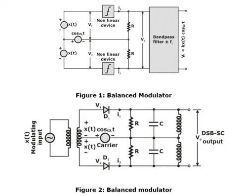
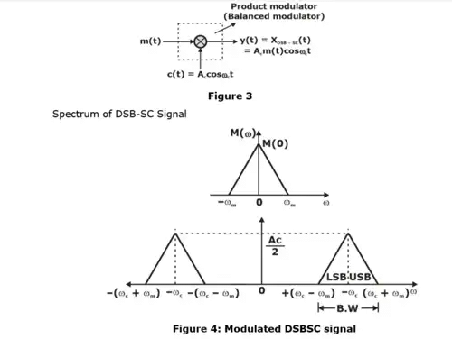
Transmission B.W = 2ωm
(b) Ring Modulator
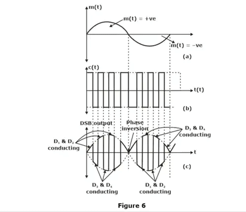
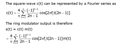
One of the most useful product modulators that is well suited for generating a DSBSC modulated wave is the ring modulator, it is also known as double-balanced modulator or lattice. The four diodes in figure shown below forms a ring in which they all point the same way. These diodes are controlled by a square-wave carrier c(t) of frequency fc which is applied by means of two center-tapped transformers. We assume that the diodes are ideal, and the transformers are perfectly balanced When the carrier supply is positive, the outer diodes (D1, D2) are switched on, presenting zero impedance, whereas the inner diodes (D3. D4) are switched off, presenting infinite impedance.
We see that there is no output from the modulator at the carrier frequency; that is, the modulator output consists entirely of modulation products.
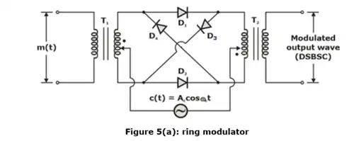
- Four diodes are connected to form a ring.
- Used for the generation of DSB-SC waves.
(iv) Operation of the Circuit:
From the circuit diagram of ring modulator, we can explain the operation of the circuit as follows.
- The operation is explained with the assumptions that the diodes act as perfect switches and they are switched on and off by the RF carrier signal. This is because the amplitude and frequency of the carrier is higher than that of the modulating signal.
- The operation can be divided into different modes without the modulating signal and with modulating signal as follows:
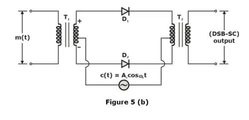
For (+)ve half cycle of c(t)
Diode D1 and D2 is ON.
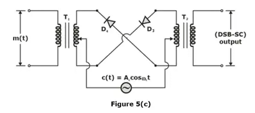
For (–)ve half cycle of c(t)
Diode D3 and D4 ON.
(v) Hilbert Transform:
A signal x(t) and its Hilbert transform Xh(t) has the following characteristics
- A signal x(t) and its Hilbert transform Xh(t) have the same energy density spectrum.
- A signal x(t) and its Hilbert transform Xh(t) have the same autocorrelation function.
- A signal x(t) and its Hilbert transform Xh(t) are mutually orthogonal

- If Xh(t) is a Hilbert transform of x(t), then the Hilbert transform of Xh(t) is - x(t), i.e If H[x(t)] = Xh(t), then H[Xh(t)] = - x(t)
Single Sideband Technique:
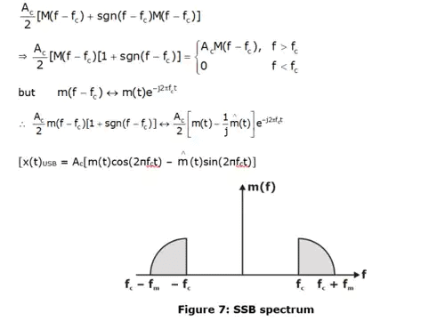
Assume the above spectrum an SSB signal in which lower side band is removed.
Let m(t) have a Fourier transform M(f), thus to eliminate the LSB we write the equation as
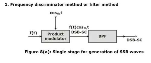
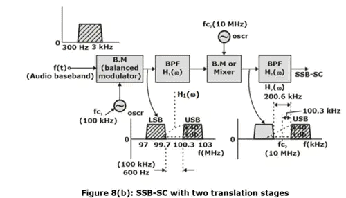
(i) Generation of SSBSC Wave:
(ii) Advantage SSB-SC over DSB-SC and AM
In SSB-SC, B.W = ωm, while in DSB-SC or AM, B.W = 2ωm. This reduction in B.W allows signals to be transmitted in the same frequency range. In SSB-SC, more power is saved, and this saved power can be used to produce a stronger signal.
(iii) Conventional AM Over DSBSC and SB Signals
- The demodulation or detection of AM signal is simpler than DSBSC and SSB systems. The conventional AM can be demodulated by rectifier or envelope detector. Detection of DSBSC and SSB is rather difficult and expensive.
- Furthermore, it is quite easier to generate conventional AM signals at high power levels as compared to DSBSC and SSB signals. For this reason, conventional AM systems are used for broadcasting purpose.
- The advantage of DSBSC and SSB systems over conventional AM system is that the former requires lesser power to transmit the same information.
(iv) Vestigial Sideband (VSB) Modulation Technique:
When there is vestige or relaxed in one of the sidebands in DSBSC signal then this is called VSB modulation technique.
VSB wave equation is:

- where F represents the fraction.
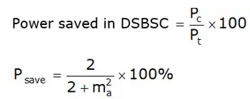
(v) Power Saving:
In DSB-SC:
In SSB-SC:

(vi) Power Relations in VSB Wave:
The power of VSB wave PVSB can be calculated as

(vii) SSB Over DSBSC and VSB:
- Demodulation of DSBSC and SSB waves is done using coherent carrier signal at a receiver.
- Envelope detector can also be used to recover message by passing received VSB signal through it.
- SSB scheme needs only one-half of the bandwidth required in DSBSC system and less than that required in VSB also. Thus, we can say that SSB modulation scheme is the most efficient scheme among DSBSC and VSB schemes. SSB modulation scheme is used for long distance transmission of voice signals because it allows the longer spacing between repeaters.
- A device that performs the frequency translation of a modulated signal is known as a frequency mixer. The operation is often collect frequency mixing, frequency conversion or heterodyning.
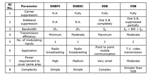
Performance Comparison of AM Techniques:
|
14 videos|44 docs|30 tests
|
FAQs on Types of AM & Its Classification - Communication System - Electronics and Communication Engineering (ECE)
| 1. What is AM and what are the different types of AM techniques? |  |
| 2. What is the single sideband technique in AM? |  |
| 3. How does the performance of different AM techniques compare? |  |
| 4. What are the advantages of using the single sideband technique in AM? |  |
| 5. Are there any limitations or challenges associated with the single sideband technique in AM? |  |

