Operational Amplifiers - 1

Introduction
An operational amplifier (Op-Amp) is an integrated circuit that amplifies the difference between two input voltages and produces a single output. From signal point of view, the Op-Amp has two input terminals and one output terminal as shown in figure below.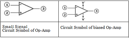
Characteristics of Ideal Op-Amp
The ideal Op-Amp senses the difference between two input signals and amplifies this difference to produce an output signal. The output terminal voltage is the voltage at the output terminal measured with respect to ground.
The ideal Op Amp equivalent is shown in figure below: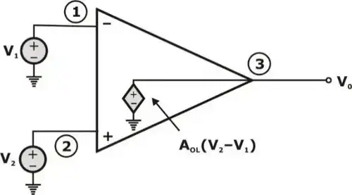
Here,
AOL = open loop gain
- It has infinite input impedance and zero output impedance.
- The common mode gain is zero (or) equivalently, common mode rejection ratio is infinite.
- The open loop gain of ideal op-amp is infinite
- The ideal op-amp has infinite bandwidth and infinite slew-rate.
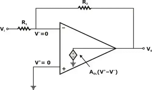
- We stated that if the open loop gain (AOL) is very high, then the two input V1 and V2 must be nearly equal. Since, if V2 is at ground potential, voltage V1 must also be approximately zero volts as shown below.
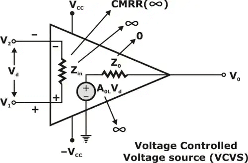 Voltage Controlled Voltage Source
Transfer Characteristics of Op Amp
Transfer characteristics equation of Op-Amp: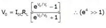
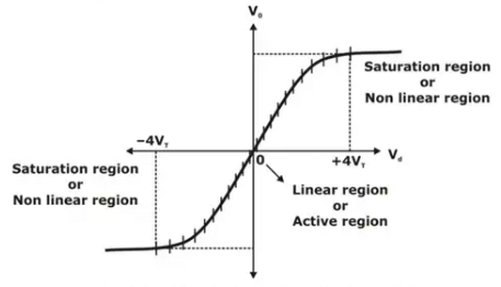 Transfer characteristics of Op Amp
Feedback in Op Amp
- Negative Feedback:
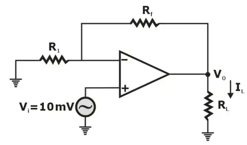 Non-Inverting AmplifierHere, Closed loop gain
Conclusion: When the Op-Amp relates to negative feedback, the voltage gain will reduce.
- Positive Feedback:
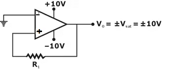 Positive Feedback Amplifier
Note: Multivibrator works in open or closed loop of positive feedback.
Virtual-Ground and Comparator
- Virtual ground theory is applicable only in "Negative feedback". It is not applicable in positive feedback and open loop.
- Comparator theory is applicable for open loop and positive feedback.
Table: Comparison between Negative feedback and Open-loop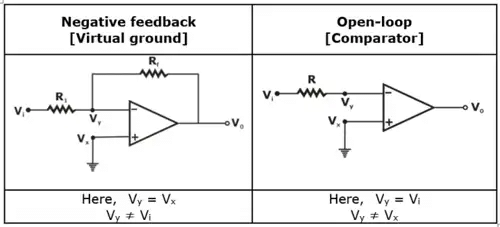
Slew-Rate
Slew rate is defined as the maximum rate at which amplifier output can change. It is expressed in Volts per microsecond (V/μs) i.e.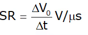
Here, ∆V0 = Small change in output voltage in a small interval ∆t.
In terms of input voltage, slew rate can be expressed as: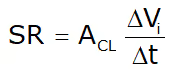
Here, ACL = closed loop gain,
∆Vi = Small change in input voltage in a small interval ∆t
Differential and Common Mode operation
- Differential Inputs
When separate inputs are applied to the op-Amp, the resulting difference signal is the difference between the two inputs
i.e.
Vd = Vi1 - Vi2
Here, Vi1, Vi2 = inputs to the op-Amp. - Common Inputs
If there is no difference between the input signals, a common signal element due to the two input signals can be defined as the average of the sum of the two signals.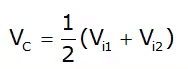
Here, Vi1, Vi2 are the inputs to the Op-Amp. - Output-Voltage
Since, any signal applied to an Op-Amp is generally have both in phase and out of phase components, the resulting output can be expressed as:
V0 = AdVd + AcVc
Here,
Ad = differential voltage
Vc = Common voltage
Ad = Differential gain of the amplifier
Ac = common mode gain of the amplifier Common Mode Rejection Ratio: (CMRR)
CMRR is defined as the ratio of differential voltage gain to the common mode gain.
i.e. CMRR = Ad/Ac
In decibels, we may express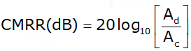
Applications of Operational amplifiers
- Inverting Amplifier
- Non-inverting Amplifier
- Differentiator
- Differential Amplifier
- Voltage follower
- Selective inversion circuit
- Current-to-voltage converter
- Active rectifier
- Integrator
- Comparator
- Filters
- Voltage comparator
- Signal Amplifier
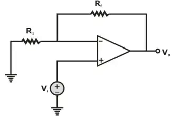
- Inverting-Amplifier
The voltage gain for the inverting Amplifier is given by:
Av = -Rf/R1
Below figure shows the inverting amplifier.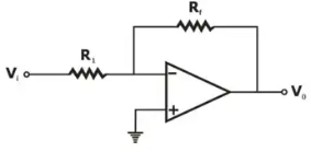
- Non-Inverting Amplifier
The voltage gain for the non-inverting amplifier is given by:
Non-Inverting Amplifier
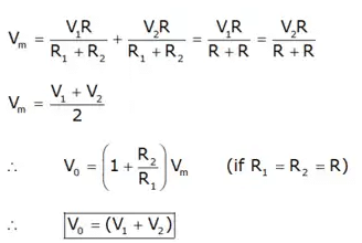
- Voltage Adder
(i) Inverting Adder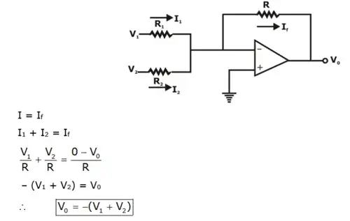
(ii) Non-Inverting Adder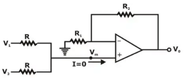
- Voltage Subtractor Circuit
A Voltage Subtractor circuit consist of an inverting amplifier and a summing amplifier. Output of the inverting amplifier is given by: So, the output voltage of the summing amplifier is obtained as:
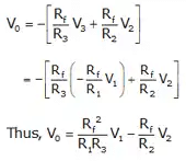
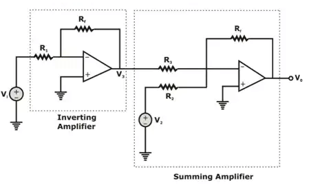 Voltage Subtractor Circuit
 - Difference Amplifier
Consider the difference amplifier shown below: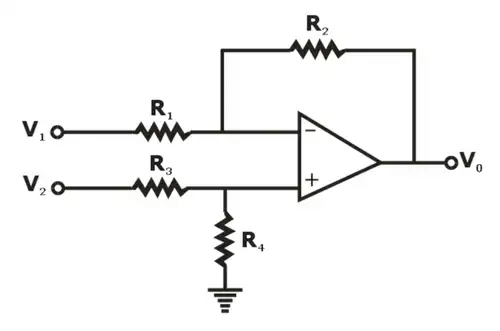 Applying Superposition, we consider only one input at a time as shown in below figures.When only V1 is present,
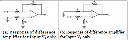
 When only source V2 Is present, the output Is
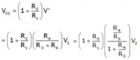
Now, on adding V01 and V02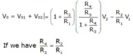
Then, the net output voltage = V0 = R2/R1 (V2 - V1) - Differentiator Circuit
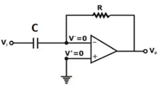 Differentiator circuitApplying KCL at Inverting node, we have
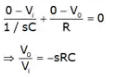
It exhibits a zero at origin, so the circuit acts as a differentiator (high pass filter) We can also use the input-output relationship in time domain as:
- Integrator Circuit
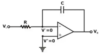 Applying KCL at inverting terminal, we have
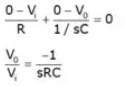
Since, the transfer function shows a pole at the origin, the circuit operates as an Integrator (low-pass filter)
Input-output relation in time domain Is -
FAQs on Operational Amplifiers - 1
| 1. What is an operational amplifier (op-amp)? |  |
| 2. How does an op-amp work? | |
| 3. What are the characteristics of an ideal op-amp? | |
| 4. Can op-amps be used for mathematical operations? | |
| 5. What are the different types of op-amp configurations? | |


 | Explore Courses for Electronics and Communication Engineering (ECE) exam |
 | Get EduRev Notes directly in your Google search |