Half Wave Rectifier | Power Electronics - Electrical Engineering (EE) PDF Download
What is a Half Wave Rectifier?
- A half wave rectifier is defined as a type of rectifier that only allows one half-cycle of an AC voltage waveform to pass, blocking the other half-cycle. Half-wave rectifiers are used to convert AC voltage to DC voltage, and only require a single diode to construct.
- A rectifier is a device that converts alternating current (AC) to direct current (DC). It is done by using a diode or a group of diodes. Half wave rectifiers use one diode, while a full wave rectifier uses multiple diodes.
- The working of a half wave rectifier takes advantage of the fact that diodes only allow current to flow in one direction.
Half Wave Rectifier Theory
- A half wave rectifier is the simplest form of rectifier available. We will look at a complete half wave rectifier circuit later – but let’s first understand exactly what this type of rectifier is doing.
- The diagram below illustrates the basic principle of a half-wave rectifier. When a standard AC waveform is passed through a half-wave rectifier, only half of the AC waveform remains. Half-wave rectifiers only allow one half-cycle (positive or negative half-cycle) of the AC voltage through and will block the other half-cycle on the DC side, as seen below.

- Only one diode is required to construct a half-wave rectifier. In essence, this is all that the half-wave rectifier is doing.
- Since DC systems are designed to have current flowing in a single direction (and constant voltage – which we’ll describe later), putting an AC waveform with positive and negative cycles through a DC device can have destructive (and dangerous) consequences. So we use half-wave rectifiers to convert the AC input power into DC output power.
But the diode is only part of it – a complete half-wave rectifier circuit consists of 3 main parts:
- A transformer
- A resistive load
- A diode
A half wave rectifier circuit diagram looks like this: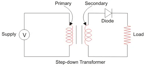
We’ll now go through the process of how a half-wave rectifier converts an AC voltage to a DC output. First, a high AC voltage is applied to the to the primary side of the step-down transformer and we will get a low voltage at the secondary winding which will be applied to the diode.

During the positive half cycle of the AC voltage, the diode will be forward biased and the current flows through the diode. During the negative half cycle of the AC voltage, the diode will be reverse biased and the flow of current will be blocked. The final output voltage waveform on the secondary side (DC) is shown in figure 3 above. This can be confusing on first glance – so let’s dig into the theory of this a bit more. We’ll focus on the secondary side of the circuit. If we replace the secondary transformer coils with a source voltage, we can simplify the circuit diagram of the half-wave rectifier as:
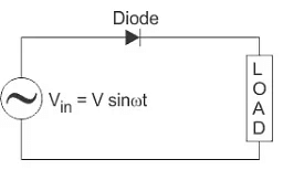 Now we don’t have the transformer part of the circuit distracting us.
For the positive half cycle of the AC source voltage, the equivalent circuit effectively becomes: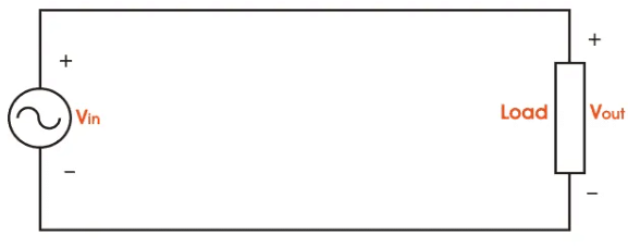 This is because the diode is forward biased, and is hence allowing current to pass through. So we have a closed circuit.
But for the negative half cycle of the AC source voltage, the equivalent circuit becomes: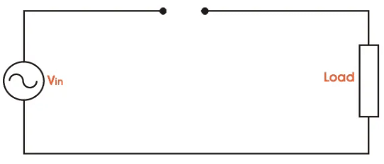
Because the diode is now in reverse bias mode, no current is able to pass through it. As such, we now have an open circuit. Since current can not flow through to the load during this time, the output voltage is equal to zero. This all happens very quickly – since an AC waveform will oscillate between positive and negative many times each second (depending on the frequency). Here’s what the half wave rectifier waveform looks like on the input side (Vin), and what it looks like on the output side (Vout) after rectification (i.e. conversion from AC to DC):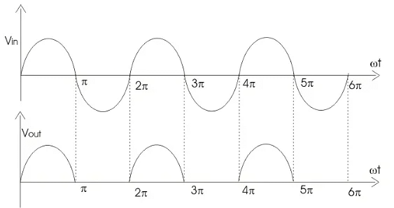
The graph above actually shows a positive half wave rectifier. This is a half-wave rectifier which only allows the positive half-cycles through the diode, and blocks the negative half-cycle. The voltage waveform before and after a positive half wave rectifier is shown in figure below.

Conversely, a negative half-wave rectifier will only allow negative half-cycles through the diode and will block the positive half-cycle. The only difference between a posive and negative half wave rectifier is the direction of the diode. As you can see in figure below, the diode is now in the opposite direction. Hence the diode will now be forward biased only when the AC waveform is in its negative half cycle.

Half Wave Rectifier Capacitor Filter
- The output waveform we have obtained from the theory above is a pulsating DC waveform. This is what is obtained when using a half wave rectifier without a filter.
- Filters are components used to convert (smoothen) pulsating DC waveforms into constant DC waveforms. They achieve this by suppressing the DC ripples in the waveform.
- Although half-wave rectifiers without filters are theoretically possible, they can’t be used for any practical applications. As DC equipment requires a constant waveform, we need to ‘smooth out’ this pulsating waveform for it to be any use in the real world.
- This is why in reality we use half wave rectifiers with a filter. A capacitor or an inductor can be used as a filter – but half wave rectifier with capacitor filter is most commonly used.
- The circuit diagram below shows how a capacitive filter is can be used to smoothen out a pulsating DC waveform into a constant DC waveform.

Half Wave Rectifier Formula
We will now derive the various formulas for a half wave rectifier based on the preceding theory and graphs above.
Ripple Factor of Half Wave Rectifier
- ‘Ripple’ is the unwanted AC component remaining when converting the AC voltage waveform into a DC waveform. Even though we try out best to remove all AC components, there is still some small amount left on the output side which pulsates the DC waveform. This undesirable AC component is called ‘ripple’.
- To quantify how well the half-wave rectifier can convert the AC voltage into DC voltage, we use what is known as the ripple factor (represented by γ or r). The ripple factor is the ratio between the RMS value of the AC voltage (on the input side) and the DC voltage (on the output side) of the rectifier.
The formula for ripple factor is:
Which can also be rearranged to equal:

The ripple factor of half wave rectifier is equal to 1.21 (i.e. γ = 1.21). Note that for us to construct a good rectifier, we want to keep the ripple factor as low as possible. This is why we use capacitors and inductors as filters to reduce the ripples in the circuit.
Efficiency of Half Wave Rectifier
Rectifier efficiency (η) is the ratio between the output DC power and the input AC power. The formula for the efficiency is equal to:
The efficiency of a half wave rectifier is equal to 40.6% (i.e. ηmax = 40.6%)
RMS value of Half Wave Rectifier
To derive the RMS value of half wave rectifier, we need to calculate the current across the load. If the instantaneous load current is equal to iL = Imsinωt, then the average of load current (IDC) is equal to:
Where Im is equal to the peak instantaneous current across the load (Imax). Hence the output DC current (IDC) obtained across the load is:
For a half-wave rectifier, the RMS load current (Irms) is equal to the average current (IDC) multiple by π/2. Hence the RMS value of the load current (Irms) for a half wave rectifier is:
Irms = Im/2
Where Im= Imax which is equal to the peak instantaneous current across the load.
Peak Inverse Voltage of Half Wave Rectifier
- Peak Inverse Voltage (PIV) is the maximum voltage that the diode can withstand during reverse bias condition. If a voltage is applied more than the PIV, the diode will be destroyed.
Form Factor of Half Wave Rectifier
Form factor (F.F) is the ratio between RMS value and average value, as shown in the formula below:
F.F = RMS Value/Average Value
The form factor of a half wave rectifier is equal to 1.57 (i.e. F.F= 1.57).
Output DC Voltage
The output voltage (VDC) across the load resistor is denoted by:
Applications of Half Wave Rectifier
- Half wave rectifiers are not as commonly used as full-wave rectifiers. Despite this, they still have some uses:
- For rectification applications
- For signal demodulation applications
- For signal peak applications
Advantages of Half Wave Rectifier
- The main advantage of half-wave rectifiers is in their simplicity. As they don’t require as many components, they are simpler and cheaper to setup and construct.
- As such, the main advantages of half-wave rectifiers are:
- Simple (lower number of components)
- Cheaper up front cost (as their is less equipment. Although there is a higher cost over time due to increased power losses)
Disadvantages of Half Wave Rectifier
- They only allow a half-cycle through per sinewave, and the other half-cycle is wasted. This leads to power loss.
- They produces a low output voltage.
- The output current we obtain is not purely DC, and it still contains a lot of ripple (i.e. it has a high ripple factor)
3 Phase Half Wave Rectifier
- All of the theory above has dealt with a single phase half wave rectifier. Although the principle of a 3 phase half wave rectifier is the same, the characteristics are different. The waveform, ripple factor, efficiency, and RMS output values are not the same.
- The three-phase half wave rectifier is used for the conversion of three phase AC power to DC power. Here the switches are diodes, and hence they are uncontrolled switches. That is to say, there is no way of controlling the on and off times of these switches.
- The 3 phase half wave diode rectifier is generally constructed with a three-phase supply connected to a three-phase transformer where the secondary winding of the transformer is always connected via star connection. This is because the neutral point is required to connect the load back to the transformer secondary windings, providing a return path for the flow of power.
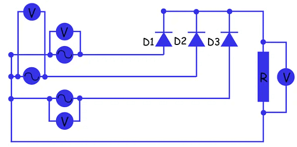
- A typical configuration of a three-phase half wave rectifier supplying a purely resistive load is shown below. Here, each phase of the transformer is considered as an individual alternating source. The simulation and measurement of voltages are as shown in the circuit below. Here we have connected an individual voltmeter across each source as well as across the load.

The three-phase voltages are shown below.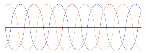 The voltage across the resistive load is shown below. The voltage is shown in black.
So we can see from the above figure that the diode D1 conducts when the R phase has a value of thevoltage that is higher than the value of the voltage of the other two phases,and this condition begins when the R phase is at a 30o and repeats after every complete cycle. That is to say, the next time diode DI begins to conduct is at 390o. Diode D2 takes over conduction from D1 which stops conducting at angle 150o because at this instant the value of voltage in B phase becomes higher than the voltages in the other two phases. So each diode conducts for an angle of 150o – 30o = 120o.
Here, the waveform of the resulting DC voltage signal is not purely DC as it is not flat,but rather it contains a ripple. And the frequency of the ripple is 3 × 50 = 150 Hz.
The average of the output voltage across the resistive load is given by
Where,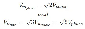
The RMS value of the output voltage is given by

The ripple voltage is equal to,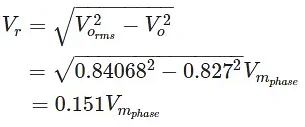
And the voltage ripple factor is equal to,

The equation above shows that the voltage ripple is significant. This is undesirable as this leads to unnecessary power loss.
DC output power,

AC input power,

Efficiency,

Even though the efficiency of the 3 phase half-wave rectifier is seemingly high, it is still less than the efficiency provided by a 3 phase full wave diode rectifier. Although three phase half wave rectifiers are cheaper, this cost saving is insignificant compared to the money lost in their higher power losses. As such, three-phase half-wave rectifiers are not commonly used in industry.
|
5 videos|51 docs|46 tests
|


