Important Diagrams: Ray Optics - Light: Reflection and Refraction


Reflection of Light
Reflection of light is the phenomenon in which light rays bounce off a surface and return to the same medium. The reflected ray lies in the same plane as the incident ray and the normal to the surface at the point of incidence.
The behaviour of reflection is described by the laws of reflection:
- First law: The incident ray, the reflected ray and the normal to the reflecting surface at the point of incidence all lie in the same plane.
- Second law: The angle of incidence is equal to the angle of reflection. In symbols, if the angle of incidence is θi and the angle of reflection is θr, then θi = θr.
These laws of reflection are applicable to all types of reflecting surfaces including spherical mirrors.
Types of reflection:
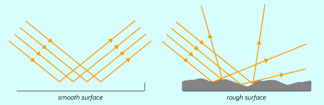
- Regular (specular) reflection: Occurs from smooth, polished surfaces such as plane mirrors. Parallel incident rays remain parallel after reflection and a clear image is formed.
- Diffuse reflection: Occurs from rough surfaces such as paper or cloth. Parallel incident rays are scattered in many directions and no clear image is formed.
Applications and examples: Plane mirrors for grooming, periscopes, rear-view mirrors (convex mirrors used in vehicles) and optical instruments that use controlled reflection.
Refraction of Light
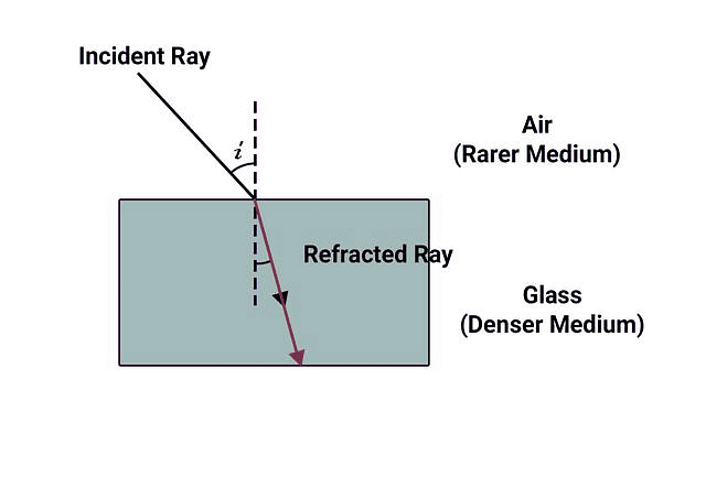
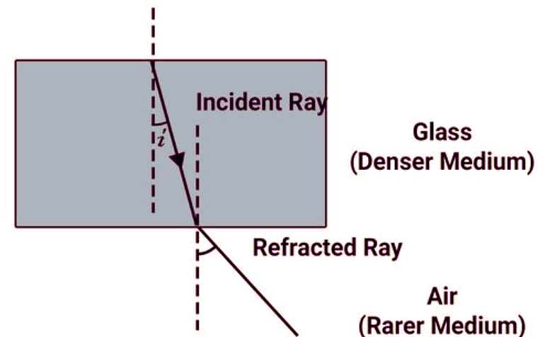
Refraction is the change in direction of light when it travels obliquely from one transparent medium to another due to change in its speed.
A ray bends towards the normal when it passes from a rarer to a denser medium and away from the normal when it passes from a denser to a rarer medium.
Key terms:
- Incident ray: The ray entering the boundary from the first medium.
- Refracted ray: The ray that travels in the second medium after refraction.
- Normal: An imaginary line drawn perpendicular to the surface at the point of incidence.
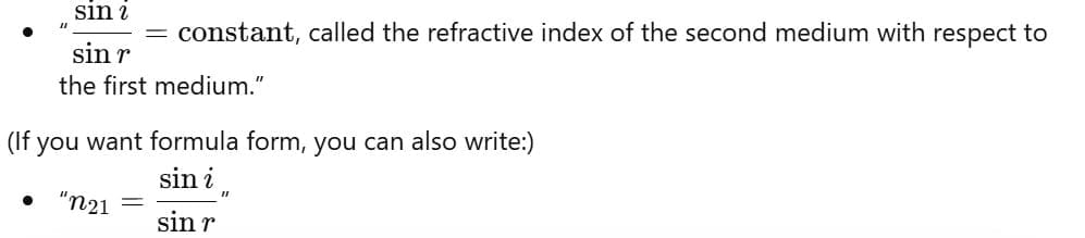
- Refractive index (relative): For two media 1 and 2, Snell's law gives the relation between angles of incidence and refraction.
Snell's law of refraction (relation between angles and refractive indices):
Observed effects and examples: A straw in a glass of water appears bent at the surface due to refraction; formation of rainbows is due to dispersion of light by water droplets combined with refraction and reflection.
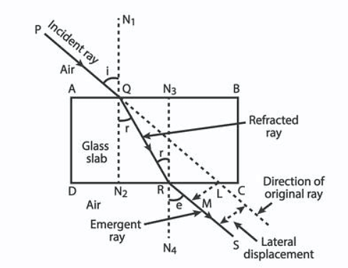
Refraction through a Rectangular Glass Slab
When a ray of light enters a rectangular glass slab from air, it refracts at the air-glass surface and again at the glass-air surface when it emerges. The key observations are:
- The ray bends towards the normal on entering the denser medium (glass) and bends away from the normal on emerging into the rarer medium (air).
- The emergent ray is parallel to the incident ray but is displaced sideways; this is called lateral displacement.
- The amount of lateral displacement depends on the thickness of the slab, the angle of incidence and the refractive index of the slab.
Spherical Mirrors: Concave and Convex
Basic terms for spherical mirrors:
- Pole (P): The middle point of the mirror surface.
- Centre of curvature (C): Centre of the sphere of which the mirror is a part.
- Principal axis: The line joining P and C.
- Focal point (F): The point where parallel rays near the principal axis converge (concave) or appear to diverge from (convex).
- Focal length (f): The distance PF. For a spherical mirror, \( f = \dfrac{R}{2} \) where R is the radius of curvature (PC).
Mirror formula and magnification:
\( \dfrac{1}{v} + \dfrac{1}{u} = \dfrac{1}{f} \)
\( m = \dfrac{h_i}{h_o} = \dfrac{v}{u} \)
Here u = object distance, v = image distance, f = focal length, h_o = object height, h_i = image height. Use the sign convention appropriate for spherical mirrors when solving numerical problems.
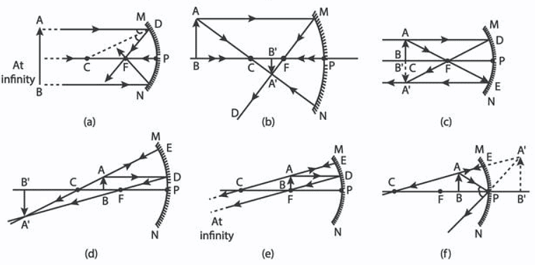
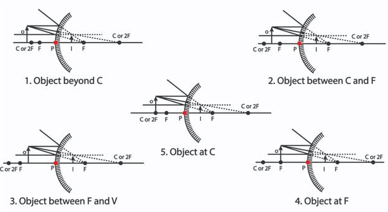
Concave mirror - image formation (qualitative cases)
- Object beyond C: Image is real, inverted, smaller than the object and formed between C and F.
- Object at C: Image is real, inverted, same size as the object and formed at C.
- Object between C and F: Image is real, inverted, larger than the object and formed beyond C.
- Object at F: Rays after reflection are parallel and the image is formed at infinity (no finite image).
- Object between F and P: Image is virtual, erect and larger than the object; it appears behind the mirror.
Convex mirror - image formation
- A convex mirror always forms a virtual, erect and diminished image behind the mirror, irrespective of the object position.
- Such mirrors have a wide field of view and are used as rear-view mirrors on vehicles.
Thin Lenses: Convex and Concave
Basic lens terms:
- Optical centre (O): The central point of the lens.
- Principal axis: Line passing through the optical centre and the centres of curvature of the lens surfaces.
- Principal focus (F): For a convex lens, parallel rays converge at F after refraction; for a concave lens, parallel rays appear to diverge from F.
- Focal length (f): Distance OF.
Lens formula and magnification:
\( \dfrac{1}{v} - \dfrac{1}{u} = \dfrac{1}{f} \)
\( m = \dfrac{h_i}{h_o} = - \dfrac{v}{u} \)
Sign conventions for lenses are used when solving numerical problems; for thin lenses follow the usual Cartesian sign convention.
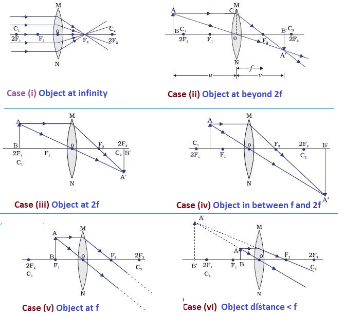
Convex (converging) lens - image formation (qualitative cases)
- Object beyond 2F: Image is real, inverted and diminished, formed between F and 2F on the other side.
- Object at 2F: Image is real, inverted and same size, formed at 2F on the other side.
- Object between F and 2F: Image is real, inverted and magnified, formed beyond 2F.
- Object at F: Image formed at infinity (parallel rays); no finite image.
- Object between F and optical centre: Image is virtual, erect and magnified, formed on the same side as the object.
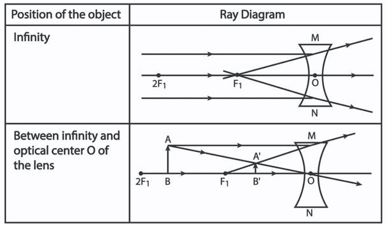
Concave (diverging) lens - image formation
- A concave lens always forms a virtual, erect and diminished image on the same side as the object.
- The image lies between the optical centre and the principal focus of the concave lens.
Practical Notes and Applications
- Understanding reflection and refraction is essential for designing optical instruments such as cameras, microscopes, telescopes and corrective lenses.
- Convex mirrors are used where a wide field of view is required (vehicle side mirrors, store security mirrors).
- Concave mirrors are used to focus light (torch reflectors, shaving mirrors) and in astronomical telescopes.
- Convex lenses form images in cameras and the human eye; concave lenses are used in spectacles for short-sightedness.
Summary
Reflection and refraction are fundamental behaviours of light at boundaries. The laws of reflection and Snell's law of refraction govern ray directions. Spherical mirrors and thin lenses form images whose positions and sizes follow the mirror and lens formulas. Ray diagrams, principal rays and the defined points (pole, focal point, centre of curvature, optical centre) are used to locate and classify images as real or virtual, inverted or erect, and magnified or diminished.
FAQs on Important Diagrams: Ray Optics - Light: Reflection and Refraction
| 1. What are the main differences between reflection and refraction of light? |  |
| 2. How do I draw and label a ray diagram for refraction through a glass slab correctly? | |
| 3. Why does light bend when it travels from one medium to another? | |
| 4. What's the difference between real and virtual images formed by mirrors and lenses in ray diagrams? | |
| 5. How do I identify the critical angle and total internal reflection in ray optics diagrams? | |