
Best Study Material for Mechanical Engineering Exam
Gears | Mechanical Engineering SSC JE (Technical) PDF Download
INTRODUCTION
- Gears
- The efficiency of gear drives is very high even up to 99% in case of spur gears.
- Spur gears are used only when shafts are parallel, spur gears impose radial loads on the shafts
- In Helical gear, the magnitude of helix angle of pinion and gear is same, however the hand of helix is opposite. Helical gears impose radial and thrust loads on shaft.
- A double helical gears with a small groove between two helix is called herringbone gears. There is no thrust load on shaft herringbone gears are used only for parallel shafts.
- Bevel gears have the shape of truncated cone, used for shafts which are at right angles to each other. Bevel gear impose radial and thrust load on shaft.
- Worm gears are used for shafts, the axes of which do not intersect and are perpendicular to each other. The worm imposes high thrust load, while worm wheel imposes high radial load on the shafts. It is characterized by high speed reduction ratio used in material handling equipment.
- When the axes of two shafts are neither perpendicular nor intersecting spiral helical gears are employed.
Fundamental Law of Gearing
- The common normal to the tooth profile at the point of contact should always pass through a fixed point, called pitch point; in order to obtain a constant velocity ratio.
 is the velocity of point C when it is considered on gear 1, while CB is velocity of point C, when it is considered on gear 2 CA perpendicular to O1C and
  perpendicular to O2C.
Figure 7-2 shows two mating gear teeth, in which
- Tooth profile 1 drives tooth profile 2 by acting at the instantaneous contact point K.
- N1N2 is the common normal of the two profiles.
- N1 is the foot of the perpendicular from O1 to N1N2
- N2 is the foot of the perpendicular from O2 to N1N2.
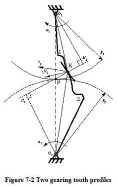
Although the two profiles have different velocities V1 and V2 at point K, their velocities along N1N2 are equal in both magnitude and direction. Otherwise the two tooth profiles would separate from each other. Therefore, we have
 (7-1)
(7-1)
or
 (7-2)
(7-2)
We notice that the intersection of the tangency N1N2 and the line of center O1O2 is point P, and
 (7-3)
(7-3)
Thus, the relationship between the angular velocities of the driving gear to the driven gear, or velocity ratio, of a pair of mating teeth is
 (7-4)
(7-4)
Point P is very important to the velocity ratio, and it is called the pitch point. Pitch point divides the line between the line of centers and its position decides the velocity ratio of the two teeth. The above expression is the fundamental law of gear-tooth action.
- Only involute and cycloidal curves satisfy this fundamental law of gearing.
- In case of cycloid curves, the pitch point is fixed but the inclination a varies.
- The module (m) is defined as the inverse of diametral pitch.
- Diametral pitch

- Circular pitch

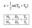
- Centre distance between two gears
- Diametral pitch
- Standard system of Gears
- There are two system for the shape of gear tooth depending upon pressure angle. 14.5° and 20° involute system. The 20° pressure angle system has the following advantage.
- It reduces the risk of undercutting.
- The tooth is stronger with higher load carrying capacity.
- It has greater length of contact.
- It gives larger radius of curvature.
The main advantage of 14.5° pressure angle system is its quietness of operations.
- In the design of gears, the number of teeth are decided from speed reduction and the module is calculated from strength and wear consideration.
- There are two system for the shape of gear tooth depending upon pressure angle. 14.5° and 20° involute system. The 20° pressure angle system has the following advantage.
Force Analysis
- According to fundamental law of gearing, this resultant force PN always acts along the pressure line.
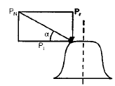
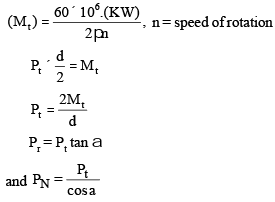
- The tangential component (Pt) is a useful load because it determines the magnitude of torque and consequently the power, which is transmitted.
- The radial component (Pr) is a separating force which is always directed towards the centre of gear.
- As the point of contacts moves, the magnitude of resultant force PN changes.
- Minimum Number of Teeth : on pinion to avoid interference.
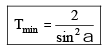
- Tmin can be further reduced by giving a slight radius to the tip of tooth.
- For 20° full depth involute tooth system, it is always sefe to assume the No. of teeth on the pinion as 18 to 20.
- If the face width is too large; there is a possibility of concentration of load at one end of gear tooth due to misalignment, elastic deformation and warping gear tooth. optimum range of face width is 8m < b < 12 m
Lewis Equation
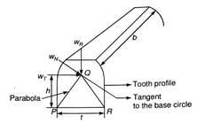
The first equation used for bending stress was the Lewis equation. This is derived by treating the tooth as a simple cantilever and with tooth contact occuring at the tip as shown below:
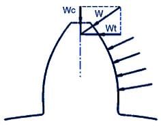
Only the tangent component(Wt) is considered. It is also assumed that only one pair of teeth is in contact. Stress concentrations at the tooth root fillet are ignored. It can be shown that the maximum bending stress occurs at the tangent points on the parabola shown above. Use of the standard equation for bending stress(σ=Mc/I) leads to:
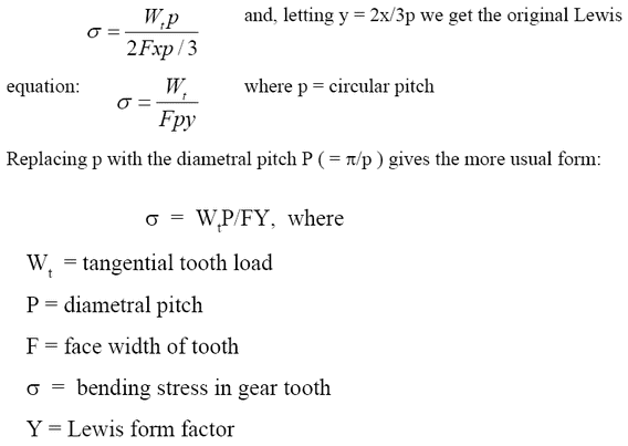
 The value of Y independent of the size of tooth and depend only on No. of teeth on gear and system of teeth.
Maximum tangential force Pt called beam strength and replaced by Sb.
 known as Lewis equation.
- In design when same material is used for pinion and gear, the product ( sb × Y) decides weaker between pinion and gear the lewis form factor (Y) is always less for pinion than gear, for same material pinion is always weaker than gear.
- Effective load on Gear Tooth

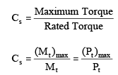
Since torque developed by source and required by driven machine varies during working cycle. It is balanced by flywheel. In gear design maximum force is the criterion. This is accounted by means of a service factor.
- Service factor
- The dynamic force is induced due to the following factors :
- Inaccuracies of tooth profile
- Errors in tooth spacing
- Misalignment between bearings
- Elasticity of parts
- Inertia of rotating mass.
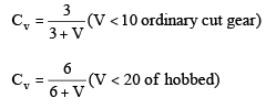
Due to inability in calculation of dynamic load a velocity factor (Cv) developed,
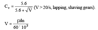
d — diameter of gear (in mm)
Effective load
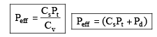
where, Pd is the dynamic load
The document Gears | Mechanical Engineering SSC JE (Technical) is a part of the Mechanical Engineering Course Mechanical Engineering SSC JE (Technical).
All you need of Mechanical Engineering at this link: Mechanical Engineering
|
5 videos|103 docs|59 tests
|


FAQs on Gears - Mechanical Engineering SSC JE (Technical)
| 1. What is Gears SSC? |  |
| 2. What kind of exams does Gears SSC cover? | |
Ans. Gears SSC covers a wide range of competitive exams, including banking exams, SSC exams, railway exams, and other government job exams.
| 3. How can I access the exam preparation materials provided by Gears SSC? | |
Ans. To access the exam preparation materials provided by Gears SSC, you can visit their website and explore the available study materials, online courses, and mock tests. Some materials may be available for free, while others may require a subscription or purchase.
| 4. Are the study materials provided by Gears SSC effective for exam preparation? | |
Ans. Yes, the study materials provided by Gears SSC are designed to be effective for exam preparation. They are created by experienced educators and experts in the respective exam fields, and cover all the necessary topics and concepts.
| 5. Can Gears SSC help me with exam-specific strategies and tips? | |
Ans. Yes, Gears SSC provides exam-specific strategies and tips to help you improve your performance in the exams. They offer guidance on time management, question-solving techniques, and provide valuable insights into the exam patterns and trends.
Related Exams
About this Document

1.1K Views

4.98/5
Rating

Apr 08, 2025
Last updated
Document Description: Gears for Mechanical Engineering 2025 is part of Mechanical Engineering SSC JE (Technical) preparation.
The notes and questions for Gears have been prepared according to the Mechanical Engineering exam syllabus. Information about Gears covers topics
like and Gears Example, for Mechanical Engineering 2025 Exam. Find important definitions, questions, notes, meanings, examples, exercises and tests below for Gears.
Introduction of Gears in English is available as part of our Mechanical Engineering SSC JE (Technical)
for Mechanical Engineering & Gears in Hindi for Mechanical Engineering SSC JE (Technical) course.
Download more important topics related with notes, lectures and mock test series for Mechanical Engineering
Exam by signing up for free. Mechanical Engineering: Gears | Mechanical Engineering SSC JE (Technical)
Description
Full syllabus notes, lecture & questions for Gears | Mechanical Engineering SSC JE (Technical) - Mechanical Engineering | Plus excerises question with solution to help you revise complete syllabus for Mechanical Engineering SSC JE (Technical) | Best notes, free PDF download
Information about Gears
In this doc you can find the meaning of Gears defined & explained in the simplest way possible. Besides explaining types of
Gears theory, EduRev gives you an ample number of questions to practice Gears tests, examples and also practice Mechanical Engineering
tests

Related Searches
practice quizzes
,Objective type Questions
,MCQs
,Summary
,Gears | Mechanical Engineering SSC JE (Technical)
,mock tests for examination
,Viva Questions
,Gears | Mechanical Engineering SSC JE (Technical)
,study material
,past year papers
,Extra Questions
,video lectures
,Gears | Mechanical Engineering SSC JE (Technical)
,shortcuts and tricks
,Free
,Exam
,Previous Year Questions with Solutions
,ppt
,Semester Notes
,Important questions
,Sample Paper
;


Additional Information about Gears for Mechanical Engineering Preparation
Gears Free PDF Download
The Gears is an invaluable resource that delves deep into the core of the Mechanical Engineering exam.
These study notes are curated by experts and cover all the essential topics and concepts, making your preparation more efficient and effective.
With the help of these notes, you can grasp complex subjects quickly, revise important points easily,
and reinforce your understanding of key concepts. The study notes are presented in a concise and easy-to-understand manner,
allowing you to optimize your learning process. Whether you're looking for best-recommended books, sample papers, study material,
or toppers' notes, this PDF has got you covered. Download the Gears now and kickstart your journey towards success in the Mechanical Engineering exam.
Importance of Gears
The importance of Gears cannot be overstated, especially for Mechanical Engineering aspirants.
This document holds the key to success in the Mechanical Engineering exam.
It offers a detailed understanding of the concept, providing invaluable insights into the topic.
By knowing the concepts well in advance, students can plan their preparation effectively.
Utilize this indispensable guide for a well-rounded preparation and achieve your desired results.
Gears Notes
Gears Notes offer in-depth insights into the specific topic to help you master it with ease.
This comprehensive document covers all aspects related to Gears.
It includes detailed information about the exam syllabus, recommended books, and study materials for a well-rounded preparation.
Practice papers and question papers enable you to assess your progress effectively.
Additionally, the paper analysis provides valuable tips for tackling the exam strategically.
Access to Toppers' notes gives you an edge in understanding complex concepts.
Whether you're a beginner or aiming for advanced proficiency, Gears Notes on EduRev are your ultimate resource for success.
Gears Mechanical Engineering Questions
The "Gears Mechanical Engineering Questions" guide is a valuable resource for all aspiring students preparing for the
Mechanical Engineering exam. It focuses on providing a wide range of practice questions to help students gauge
their understanding of the exam topics. These questions cover the entire syllabus, ensuring comprehensive preparation.
The guide includes previous years' question papers for students to familiarize themselves with the exam's format and difficulty level.
Additionally, it offers subject-specific question banks, allowing students to focus on weak areas and improve their performance.
Study Gears on the App
Students of Mechanical Engineering can study Gears alongwith tests & analysis from the EduRev app,
which will help them while preparing for their exam. Apart from the Gears,
students can also utilize the EduRev App for other study materials such as previous year question papers, syllabus, important questions, etc.
The EduRev App will make your learning easier as you can access it from anywhere you want.
The content of Gears is prepared as per the latest Mechanical Engineering syllabus.
|
© EduRev
|
Education Revolution
|


|


Signup to see your scores
go up
within 7 days!
within 7 days!
Takes less than 10 seconds to signup