Transformers - 3


Voltage Regulation
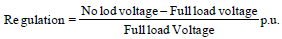
Definition: Voltage regulation of a transformer is the rise in secondary terminal voltage expressed as a fraction of the full-load rated secondary voltage when the full load (at a specified power factor) is removed while the primary (input) voltage is kept constant.
Fractional form: Vreg = (Vno-load - Vfull-load)/Vfull-load
Percentage form: % Voltage regulation = Vreg × 100
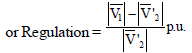
When referred to the primary or when using per-unit notation the relationships between referred voltages may be written. For an ideal transformation relation between referred secondary and primary voltages one often writes:
V′2 = a V2
Approximate Voltage Regulation
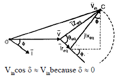
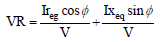
Approximate expressions for voltage regulation of a transformer are obtained by representing the transformer's series impedance by its equivalent resistance req and reactance xeq and using phasor algebra. These approximate formulae are useful for quick calculations and give insight into the influence of load power factor on regulation.
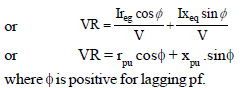
To find voltage regulation for a leading power factor, replace ø by -ø in the formulae derived for lagging power factor.
Condition for Maximum Voltage Regulation
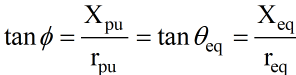
Maximum regulation occurs when the derivative of the regulation expression with respect to load power-factor angle is zero. This leads to a condition involving tan ø, the equivalent impedance angle θeq and the resistive/reactive parts.
Maximum voltage regulation occurs at a lagging power factor when tan ø is positive.
Note: Here tan ø is positive; therefore maximum voltage regulation occurs at a lagging load power factor.
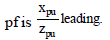
Power factor corresponding to the equivalent impedance is given by:
p.f. = req/Zeq
Condition for Zero Voltage Regulation
There exists a particular load power factor (leading) for which the phasor drop due to series reactance cancels the drop due to series resistance and the secondary no-load and full-load voltages become equal (zero regulation). The algebraic form of this condition can be written in several equivalent ways depending on which variables are used.
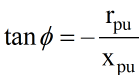
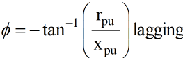
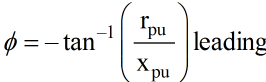
Equivalently, zero regulation occurs when the load power factor angle satisfies:
ø = (90° - θeq) leading
Negative values of tan ø indicate a leading power factor; therefore zero voltage regulation occurs when the load is sufficiently leading that the reactive voltage drop balances the resistive drop.
Remember:
- For a leading power factor greater than Xpu/Zpu, the voltage regulation will be negative (i.e. the terminal voltage at no-load is less than at full-load under the same input voltage).
Transformer Losses
Losses in a transformer are of two main kinds: core (iron) losses and copper (ohmic) losses. These determine the efficiency and heating of the machine.
Core (Iron) Loss
Core loss Pc is independent of load current and is usually taken as constant for a given supply voltage and frequency. Core loss comprises two parts:
- Hysteresis loss Ph due to repeated magnetisation of the core.
- Eddy current loss Pe due to circulating currents induced in the core material.
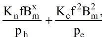
The usual empirical expressions are:
Ph = Kh · f · Bmx
Pe = Ke · f2 · Bm2
Where:
- Kh = proportionality constant depending on the quality and volume of the core material.
- Ke = proportionality constant depending on core volume, resistivity, lamination thickness and units used.
- Bm = maximum flux density in the core.
- f = frequency of the alternating flux.
- x = Steinmetz's exponent (varies approximately from 1.5 to 2.5 depending on the magnetic material).
Therefore total core loss is:
Pc = Ph + Pe
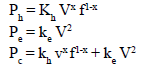
Core losses can also be expressed in terms of applied voltage and frequency; the appropriate expression for a given design is often found experimentally or from manufacturer data.
Ohmic (Copper) Loss
Ohmic loss (copper loss) occurs in both primary and secondary windings and varies with load current. The combined copper loss referred to a common side is given by:
Pcu = I2 req
where req is the equivalent resistance (primary and secondary referred to a common side) and I is the load current referred to the same side.
Note: Iron (core) loss Pi is also called constant loss because it does not depend on load current. Copper loss Pcu (I2 req) is called variable loss because it depends on the square of the load current.
Efficiency Of Transformer
Definition: Efficiency η of a transformer is the ratio of output power to input power.
η = Output power / Input power
Expressed with losses:
η = Pout / (Pout + Pc + Pcu)
Condition for Maximum Efficiency
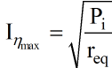
Maximum efficiency occurs when the variable losses equal the constant losses.
Pi = Pcu
i.e. Iron (core) loss = Copper (ohmic) loss.
At a given load current the copper loss is proportional to I2, so the current at which maximum efficiency occurs can be obtained from:
The kVA at maximum efficiency can be calculated from known values at a reference load. If S(known load) is the kVA at a known load and Pcu(known load) the copper loss at that known load, then kVA at maximum efficiency may be obtained from the relation:
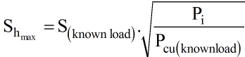
Where S(known load) = kVA at known load and Pcu(known load) = copper loss at known load.
Autotransformer
Definition: An autotransformer is a transformer in which part of the winding is common to both the primary (high-voltage side) and the secondary (low-voltage side). It is a one-winding transformer and is not electrically isolated between primary and secondary.
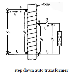
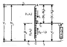
Let the number of turns on the primary section AC be N1 and the number of turns on the secondary BC be N2. If an applied voltage V1 is placed across AC, the voltage across BC is given by the turn ratio relation:

For an ideal autotransformer, neglecting losses, input power equals output power (real power):
V1 I1 cos θ1 = V2 I2 cos θ2
If the load power factors on primary and secondary are the same (cos θ1 = cos θ2), then:
V1 I1 = V2 I2
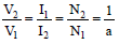
Where a denotes the transformation (turn) ratio.
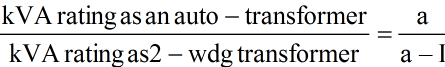
Advantages of Autotransformer over Two-Winding Transformer
- An autotransformer has higher efficiency than a two-winding transformer of the same output rating because less copper is required in the winding.
- An autotransformer has lower leakage impedance and therefore superior voltage regulation as compared with a two-winding transformer of the same rating.
- An autotransformer is more economical (cheaper) for voltages where direct connection between primary and secondary is acceptable.
Disadvantages of Autotransformer over Two-Winding Transformer
- If the turn ratio a differs far from unity the economic advantage of the autotransformer over the two-winding transformer decreases.
- The short-circuit current in an autotransformer is higher than in a corresponding two-winding transformer, which may increase fault currents in the network.
- The principal disadvantage is the lack of electrical isolation between low-voltage and high-voltage sides. An open circuit in the common winding can cause dangerously high voltages to appear on what is expected to be the low-voltage side.
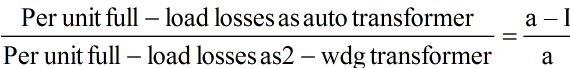
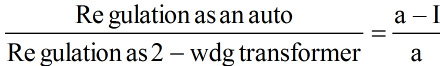
Comparison of Characteristics of Autotransformers and Two-Winding Transformers
Copper saving in autotransformer:
Cu(auto) = Cu(2wdg) -

Percentage copper saving:
% Cu saving = (1 - 1/a) × 100

Note:
- Single-phase and three-phase autotransformers are commonly employed for interconnecting power systems with voltage ratios not differing far from unity.
- Autotransformers are also used for obtaining variable output voltages where electrical isolation is not required.
Parallel Operation of 1-ø Transformers
Parallel operation of single-phase transformers is used to increase capacity, improve reliability, and allow maintenance of individual units without interrupting supply (partially).
Advantages of Parallel Operation
- With two or more transformers the supply system becomes more reliable. If one transformer develops a fault it can be removed and the remaining units can maintain power flow at reduced capacity.
- Transformers can be switched on or off according to demand, reducing losses and improving economy.
- The cost of having a standby (spare) unit is less when two or more transformers are installed and sharing the load.
Conditions for Parallel Operation
For satisfactory parallel operation of two or more single-phase transformers the following conditions must be satisfied.
Necessary Conditions
- The polarities of the transformers must be the same.
- The turn ratios of the transformers should be equal; with primaries connected to the same voltage source the secondary voltages of all transformers should be equal in magnitude.
Desirable Conditions
- The per-unit leakage impedances of the transformers, based on their own kVA ratings, should be equal.
- The ratio of equivalent leakage reactance to equivalent resistance (xeq/req) should be equal for all transformers.
This ensures that the transformers share active power and reactive volt-amperes proportional to their ratings and operate at the same power factor.
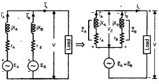
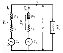
Parallel Operation at Same Voltage Ratio
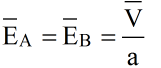
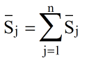
Where EA and EB are the no-load secondary voltages of transformers A and B respectively. The equivalent phasor and circuit relations can be used to find circulating currents and load sharing.
or
Similarly,

For proportional load sharing it is required that
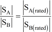
or ZA(pu) = ZB(pu)
where the per-unit values are on their respective own base.
Same Voltage Ratio and Different (x/r) Ratio
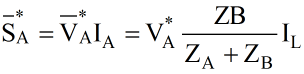
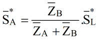
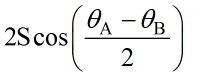
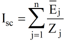
If the leakage impedance angles differ (θA ≠ θB) and both transformers supply the same apparent power S but with different impedance angles, the algebraic summation leads to resultant load SL. For the case θA > θB and equal apparent power S, the resultant load is given by the vector sum relations:
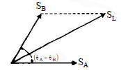
Then
Unequal Voltage Ratio
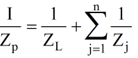
If the transformers have unequal voltage ratios, an unbalanced voltage will cause circulating currents and imbalance in load sharing. The following method is used to calculate load kVA with unequal ratios.
Steps:
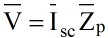
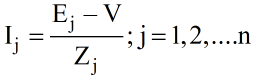
where
and
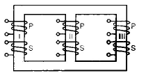
Three-phase Transformer
When three identical single-phase transformers are connected together, the arrangement is called a bank of three transformers or a three-phase transformer bank. Three-phase currents in the primaries produce three fluxes displaced by 120° in time. These fluxes pass through the yokes and central limbs; the net flux in the three central limbs taken together must be zero in a balanced system.
Core-Type Transformer
Three-phase core-type transformer from three single-phase units: When three single-phase core stacks are placed together the reluctance paths differ for the central limb and outer limbs. The central limb sees a different flux path reluctance so the exciting current of the winding on the central limb is generally less than those on the outer limbs.
Shell-Type Transformer
A three-phase shell-type transformer is obtained by placing three single-phase shell cores side-by-side with windings on the limbs.
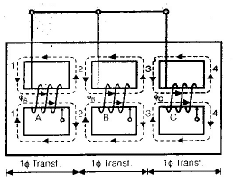
Three-phase shell type transformer with three windings wound in the same direction: In the magnetic circuits marked 2 and 3 the resultant flux is the phasor difference of component fluxes.
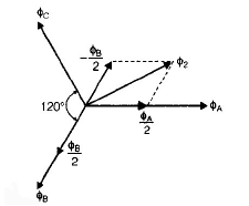
For the same flux density the cross-sectional areas at locations 2 and 3 are approximately 86% of the central core area for the shown construction.
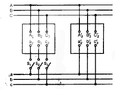
Parallel Operation of 3-ø Transformers
Successful parallel operation of three-phase transformers requires fulfilling several conditions analogous to the single-phase case plus additional requirements related to phase displacement.
- The line voltage ratios of the transformers must be equal.
- The transformers should have equal per-unit leakage impedances.
- The ratio of equivalent leakage reactance to equivalent resistance should be the same for all transformers.
- The transformers should have the same polarity.
In addition:
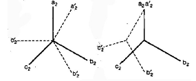
Relative phase displacement: The relative phase displacement between the secondary line voltages of the transformers must be zero. In practice this means the transformers to be connected in parallel must belong to the same vector group (same group number).
Note:
- Transformers belonging to certain group numbers (for example group numbers 3 and 4) can be paralleled successfully when their relative displacement is compatible.
- Phase sequence must be correct. An incorrect phase sequence can give zero voltage across one switch and full line voltages across others, making parallel connection impossible or unsafe.
FAQs on Transformers - 3
| 1. What is the basic principle behind the operation of transformers? |  |
| 2. How does the turns ratio affect the transformer's voltage and current? | |
| 3. What are the advantages of using transformers in electrical power transmission? | |
| 4. Can transformers be used to convert DC (direct current) to AC (alternating current)? | |
| 5. How can the efficiency of a transformer be improved? | |


 | Explore Courses for Electrical Engineering (EE) exam |
 | Get EduRev Notes directly in your Google search |