JFET Amplifier | Analog and Digital Electronics - Electrical Engineering (EE) PDF Download
| Table of contents |

|
| Introduction |

|
| What is a JFET Amplifier? |

|
| Types of JFET Amplifiers |

|
| FAQs on JFET Amplifier |

|
Introduction
- JFET amplifiers are a lengthy channel of semiconductor material. To create source/drain interconnections, ohmic connections are presented at both extremities of the semiconductor channels.
- We are using Amplifiers in power systems and communication systems. Since we have three types of transistors, there will be three types of transistor amplifiers. These are BJT amplifiers, JFET amplifiers, and MOSFET amplifiers.
The Junction Field Effect Transistor (JFET) can be operated mainly in three regions. Those are the Cut-off, Ohmic and Saturation regions. We must operate the JFET in the Ohmic or linear regions for amplification. We will use the respective JFET amplifier based on the requirement.
What is a JFET Amplifier?
As the name implies, the amplifier performs the amplification. It is an electronic circuit in which the transistor is one of the main components. Among types of transistors, JFET is the second one. If JFET is present in an amplifier circuit, it is said to be a JFET amplifier.
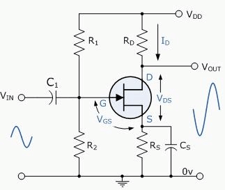
 JFET Amplifier Circuit Diagram
The basic electric quantities are voltage and current. The product of voltage and current is known as power. Using an amplifier, if we get the amplification of input voltage at the output, it is known as a voltage amplifier. Similarly, the current and power amplifiers amplify the current and power at the output.
Types of JFET Amplifiers
We can classify the JFET amplifiers based on different parameters in multiple ways. JFET configuration is one of those parameters. We will get three types of JFET amplifiers since we have three configurations of JFET. One by one, now let us discuss these amplifiers.
- Common Gate (CG) Amplifier
- Common Source (CS) Amplifier
- Common Drain (CD) Amplifier
Common Gate JFET Amplifier
In the Common Gate JFET configuration, the Gate terminal of JFET is common to both input and output.
In this configuration, we will consider the Source and Drain terminals of the JFET amplifier as the input and output terminals.
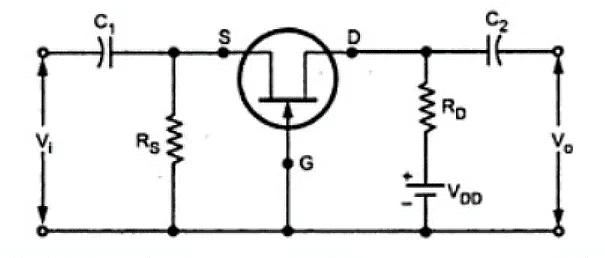
The circuit diagram of the JFET Amplifier, which is configured in Common Gate (CG), is shown below:

- The Common Gate (CG) amplifier is like the Common Base (CB) amplifier.
- In this JFET amplifier, the AC (sinusoidal) voltage waveform applied at the Source terminal will be amplified and produced at the Drain terminal. There won’t be any phase difference between the input and output waveforms.
- This JFET amplifier's input and output resistances are low and high, respectively. We can use a CG amplifier as a voltage amplifier since it has a high voltage gain. The current gain of this amplifier is approximately equal to one.
Common Source JFET Amplifier
In the Common Source JFET configuration, the Source terminal of JFET is common to both input and output.
In this configuration, we will consider the Gate and Drain terminals of the JFET as the input and output terminals.
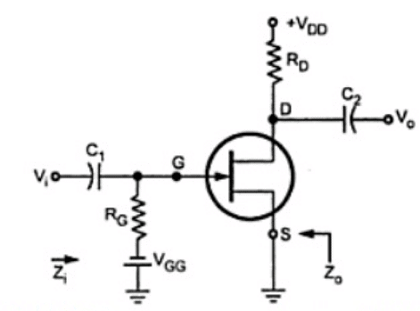
The circuit diagram of the JFET Amplifier, which is configured in Common Source (CS), is shown below.
 Common Source Circuit of JFET
- The Common Source JFET amplifier is like the Common Emitter (CE) amplifier.
- In this JFET Amplifier, the AC (sinusoidal) voltage waveform applied at the Gate terminal will be amplified and produced at the Drain terminal. But there will be a 180-degree phase difference between the input and output waveforms.
- Both the input and output resistances of this JFET amplifier have a medium value. Even this amplifier's voltage and current gain are of medium value. We can use a CS amplifier as a power amplifier, just like a CE amplifier, since it has high power gain.
Common Drain JFET Amplifier
In the Common Drain JFET configuration, the Drain terminal of the JFET amplifier is common to both input and output.
In this configuration, we will consider the Gate and Source terminals of the JFET as the input and output terminals.
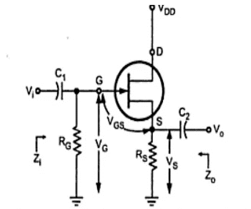
The JFET Amplifier's circuit diagram, configured in Common Drain (CD), is shown below.
 Common Drain JFET Amplifier
- The Common Drain JFET amplifier is like the Common Collector (CC) amplifier.
- In this JFET amplifier, the AC (sinusoidal) voltage waveform applied at the Gate terminal will be produced at the Source terminal with unity voltage gain. There won’t be any phase difference between the input and output waveforms.
- This JFET amplifier's input and output resistances are high and low, respectively. We can use a CD amplifier as a current amplifier since it has a high current gain. The voltage gain of this amplifier is approximately equal to one.
FAQs on JFET Amplifier
Question 1: What is JFET Amplifier?
Answer:
We have three types of JFET amplifiers based on the transistor configuration. Those are CG, CS, and CD amplifiers. CG amplifiers can be used as current buffers and voltage amplifiers. CS amplifiers can be used as power amplifiers. CD amplifiers can be used as voltage buffers and current amplifiers.
Question 2: What is a source follower in JFET Amplifier?
Answer:
In the JFET amplifier which is configured in Common Drain (CD), the output voltage across the Source terminal is the same as that of the voltage applied at the Gate terminal of JFET. Hence, it is called a source follower. The voltage gain of the source follower is equal to one.
Question 3: What is a voltage buffer in JFET Amplifier?
Answer:
An electronic circuit is said to be a voltage buffer if it has unity voltage gain. In the JFET amplifier which is configured in Common Drain (CD), the voltage across the Source and Gate terminals of the JFET is the same. Since the voltage gain of a CG amplifier is equal to one, it is called a voltage buffer.
Question 4: Are FET and JFET same?
Answer:
FET stands for Field Effect Transistor. There are two types of FETs. Those are the Junction Field Effect Transistor (JFET) and Metal Oxide Semiconductor Field Effect Transistor (MOSFET). In short, we can call JFET and MOSFET together FET because both belong to the same transistor family.
Question 5: Why is FET called a unipolar device?
Answer:
In a Bipolar Junction Transistor (BJT) the current flow is due to both charge carriers. i.e., electrons and holes. Whereas in a Field Effect Transistor (FET), the current flows due to charge carriers are of only one type. i.e., either electrons or holes. Hence, FET is called a unipolar device.
|
135 videos|181 docs|71 tests
|


