4-Bit Parallel Adder & 8-Bit Full Adder: Binary Arithmetic Circuits | Analog and Digital Electronics - Electrical Engineering (EE) PDF Download

Parallel Adders
A full adder adds two single-bit binary numbers, but multiple full adders can be combined to form parallel adders, which add multi-bit numbers. These adders are built using multiple full adders, each handling a single bit of the numbers being added.
Since parallel adder circuits can be complex when drawn with all individual gates, they are commonly represented using simplified block diagrams.
4 Bit Parallel Adder
- Fig. 4.1.3 shows how four full adders are combined to form a 4-bit parallel adder.
- This type of adder is also called a Ripple Carry Adder because the carry output of one stage becomes the carry input of the next.
- The inputs are A0 to A3 and B0 to B3, and the outputs include the sum bits S0 to S3 and the final carry-out (COUT).
- The carry propagates (ripples) from one stage to the next, which can cause delays in large-bit adders.
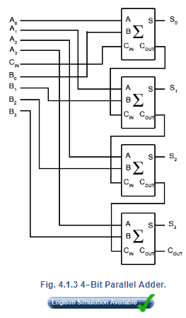
Key Points from Fig. 4.1.3:
- Each full adder processes one bit of the binary numbers.
- Carry (CIN) propagates through each stage, leading to a ripple effect.
- The final carry (COUT) represents overflow or an extra significant bit in binary addition.
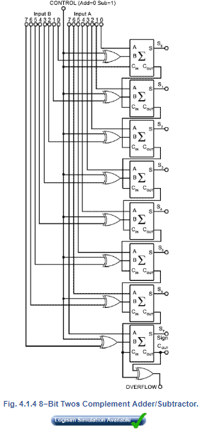
8 Bit Twos Complement Adder/Subtractor
Fig. 4.1.4 extends the 4-bit design to an 8-bit adder/subtractor.
- The circuit functions the same way for addition.
- For subtraction, the two’s complement method is used:
- Invert each bit of B (i.e., take one’s complement) using XOR gates.
- Add 1 to the inverted number (handled by feeding ‘1’ into the least significant carry input).
- Add the modified B to A using the full adder chain.
Key Observations from Fig. 4.1.4:
- An XOR gate before each B-input selects between normal B (when CONTROL = 0) and inverted B (when CONTROL = 1).
- The control input determines whether the circuit performs addition or subtraction.
- If subtraction is performed, the sum output represents the two’s complement result.
Adder/Subtractor Control
Fig. 4.1.5 contains the truth table for an XOR gate, explaining how it switches between addition and subtraction.
The XOR gate takes two inputs:
- Control bit (A)
- Operand bit (B)
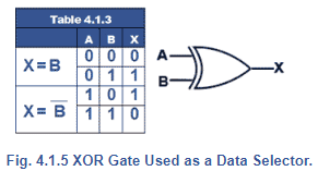
- If Control = 0: B remains unchanged → Addition
- If Control = 1: B is inverted (1’s complement) → Subtraction
Thus, the XOR gate acts as a switch, allowing the adder to function as a subtractor.
Twos Complement Overflow
1. 8-bit Adder/Subtractor:
- Designed to add or subtract 8-bit binary numbers using two’s complement notation.
- The most significant bit (bit 7) indicates the sign of the number:
- 0 = positive
- 1 = negative.
2. Limitations of Word Size:
- The word size (8-bits, 16-bits, etc.) limits the range of numbers the system can process.
- The system can only handle numbers within its designed word length.
3. Overflow in Arithmetic Operations:
- During arithmetic operations (addition or subtraction), adding two numbers can produce a result larger than the word size can hold.
- This overflow happens if the result exceeds the system’s limit, causing the result to spill over into an extra bit.
- Example: Adding positive or negative 7-bit values can result in a number that needs more than 7 bits, causing an overflow.
4. Effect of Overflow:
- In the case of two’s complement arithmetic, an overflow can change the sign of the result, losing part of the value.
- For example, an overflow can cause the value to wrap around and lose a major part of the result (e.g., 128 in decimal).
5. Overflow Detection:
- Overflow is detected by examining the carry-in (CIN) and carry-out (COUT) of the most significant bit (bit 7) adder.
- An XOR gate is used to detect overflow:
- If CIN and COUT are different, overflow has occurred.
- If CIN and COUT are the same, no overflow has occurred.
6. Corrective Measures:
- To handle overflow, extra circuits or corrective routines in software are needed to adjust or handle the overflow condition.
Adding Two Positive (In Range) Numbers
Table 4.1.4 shows the effect of adding two positive values where the sum is within the range that can be held in 7 bits (≤12710). The result of adding two positive numbers has produced a correct positive result with no carry and no overflow.

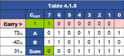
Twos Complement Subtraction
Table 4.1.5 shows a twos complement subtraction performed by adding a negative number to a positive number. The result is 3110 (within the range 0 to +12710), the sign bit is 0 indicating positive result, CIN and COUT are both 1, so no overflow is detected and the carry bit will be discarded.
Adding Twos Complement Negative Numbers
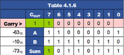
Table 4.1.6 shows the effect of adding two negative values where the sum is less than +12710 therefore a correct negative result of −7310(in twos complement notation) has been obtained. Both CIN and COUT are logic 1 and no overflow will be signalled. As only 8−bit calculations are being considered, the carry will be discarded.
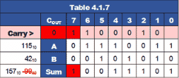
Out of Range Result Causes Overflow
When the addition of two positive numbers shown in Table. 4.1.7 results in a sum greater than +12710 the sign bit is changed from 0 to 1, incorrectly signifying a negative result. As the ‘carry in’ from bit 6 to bit 7 is 1 and the ‘carry out’ from bit 7 into the Carry bit is 0 an overflow is detected indicating an incorrect answer.
Notice that if the result of 100111012 were to be considered as an unsigned binary value, the addition in Table 4.1.7 would be correct (15710). However as the calculation is using twos complement notation, the answer of −9910 must be considered as wrong.
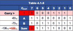
Out of Range Addition of Negative Values
Table 4.1.8 shows that adding two negative values can also produce a change in sign and a wrong twos complement result if it is greater than −12810. In this case adding −6310 and −7310 should have produced a negative result of −13610 and not +12010. To check this, the correct answer (although still with the wrong sign) could be obtained if, noting that an overflow had occurred, the answer was complemented and 1 added, giving an unsigned binary result of 100010002 which converts to 128 + 8 = 13610. Overflow errors can be corrected, but this would require either some additional electronics or a software action in response to the overflow signal.
|
135 videos|167 docs|71 tests
|
FAQs on 4-Bit Parallel Adder & 8-Bit Full Adder: Binary Arithmetic Circuits - Analog and Digital Electronics - Electrical Engineering (EE)
| 1. What is a 4-bit parallel adder and how does it work? |  |
| 2. How does an 8-bit two's complement adder/subtractor function? | |
| 3. What is the role of the adder/subtractor control in an 8-bit adder/subtractor circuit? | |
| 4. How can overflow occur in a two's complement addition, and how is it detected? | |
| 5. What are the advantages of using parallel adders over serial adders? | |


4-Bit Parallel Adder & 8-Bit Full Adder: Binary Arithmetic Circuits | Analog and Digital Electronics - Electrical Engineering (EE)
,shortcuts and tricks
,video lectures
,Exam
,Semester Notes
,Previous Year Questions with Solutions
,Summary
,Free
,mock tests for examination
,past year papers
,MCQs
,4-Bit Parallel Adder & 8-Bit Full Adder: Binary Arithmetic Circuits | Analog and Digital Electronics - Electrical Engineering (EE)
,practice quizzes
,Objective type Questions
,Important questions
,Sample Paper
,study material
,ppt
,Extra Questions
,Viva Questions
,4-Bit Parallel Adder & 8-Bit Full Adder: Binary Arithmetic Circuits | Analog and Digital Electronics - Electrical Engineering (EE)
;


4-Bit Parallel Adder & 8-Bit Full Adder: Binary Arithmetic Circuits Free PDF Download
Importance of 4-Bit Parallel Adder & 8-Bit Full Adder: Binary Arithmetic Circuits
4-Bit Parallel Adder & 8-Bit Full Adder: Binary Arithmetic Circuits Notes
4-Bit Parallel Adder & 8-Bit Full Adder: Binary Arithmetic Circuits Electrical Engineering (EE) Questions
Study 4-Bit Parallel Adder & 8-Bit Full Adder: Binary Arithmetic Circuits on the App
|
© EduRev
|
Education Revolution
|


|


