


All Exams >
Civil Engineering (CE) >
6 Months Preparation for GATE Civil Engg >
All Questions
All questions of Deflection of Beams for Civil Engineering (CE) Exam
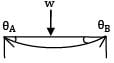
A simply supported beam of span 6 m carries two concentrated loads of 2N each at 1 m distance from each of the supports. If the flexural rigidity of the beam is constant. the slope at the support is- a)

- b)

- c)

- d)

Correct answer is option 'B'. Can you explain this answer?
A simply supported beam of span 6 m carries two concentrated loads of 2N each at 1 m distance from each of the supports. If the flexural rigidity of the beam is constant. the slope at the support is
a)
b)
c)
d)
|
|
Priyanka Sharma answered |
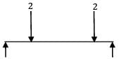
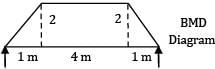
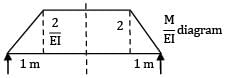
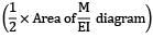
Slope at B = due to symmetry
= 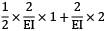
= 
= 

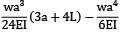
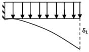
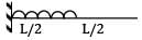
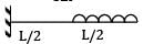
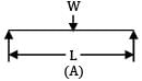
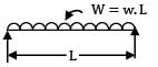
A cantilever of Length ‘L’ carries a uniformly distributed load of w per unit run for a distance ‘a’ from the fixed end. The deflection at free end is- a)

- b)

- c)

- d)
Correct answer is option 'D'. Can you explain this answer?
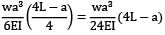
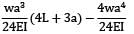
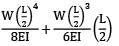
A cantilever of Length ‘L’ carries a uniformly distributed load of w per unit run for a distance ‘a’ from the fixed end. The deflection at free end is
a)
b)
c)
d)

|
Arien Instructors answered |
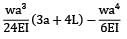
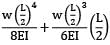
BM at B in conjugate beam = deflection at B in original beam
δn = 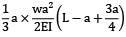
= 
= 
= 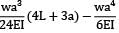
Method 2:
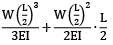
Deflection B = deflection at C + θc × (L − a)
= 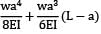
= 
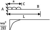
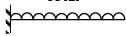
For the beam shown in the figure, the elastic curve between the supports B and C will be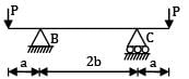
- a) Circular
- b) Parabolic
- c) Elliptic
- d) A straight line
Correct answer is option 'A'. Can you explain this answer?
For the beam shown in the figure, the elastic curve between the supports B and C will be
a)
Circular
b)
Parabolic
c)
Elliptic
d)
A straight line
|
|
Neha Joshi answered |
BMD for the loading will be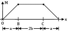
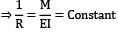
Between B and C, BMD is a straight line BM = Constant
Now, 
⇒ R = Constant Means curve of constant radius.
Hence, circular.


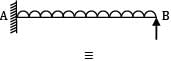
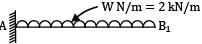
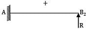
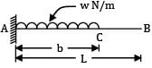
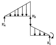
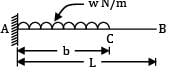
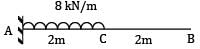
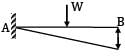
A cantilever AB, 3 m long carries a uniformly distributed load of 2 kN/m throughout its length, rests over a similar cantilever of same cross-section and same material, 2 m long and shown below. What is reaction C?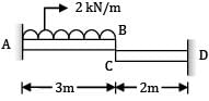
- a) 1.74 kN
- b) 3.28 kN
- c) 0.74 kN
- d) 2.48 kN
Correct answer is option 'A'. Can you explain this answer?
A cantilever AB, 3 m long carries a uniformly distributed load of 2 kN/m throughout its length, rests over a similar cantilever of same cross-section and same material, 2 m long and shown below. What is reaction C?
a)
1.74 kN
b)
3.28 kN
c)
0.74 kN
d)
2.48 kN
|
|
Priyanka Sharma answered |
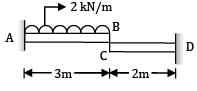
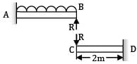
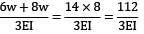
Let the reactions at C is R. Deflection at C in cantilever CD,
δC = 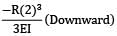
= 
= δB (in cantilever AB) ⋯ ①
YB1 = 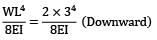
YB2 = 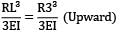
YB = YB1 + YB2 = 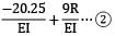
From equation ① and ②
R = 1.736 kN
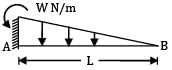
A cantilever of length (L) carries a distributed load whose intensity varies uniformly from zero at the fixed end to ‘w’ per unit length at the free end. The deflection at the free end will be- a)

- b)

- c)

- d)

Correct answer is option 'C'. Can you explain this answer?
A cantilever of length (L) carries a distributed load whose intensity varies uniformly from zero at the fixed end to ‘w’ per unit length at the free end. The deflection at the free end will be
a)
b)
c)
d)

|
Telecom Tuners answered |
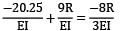
δ1 = 
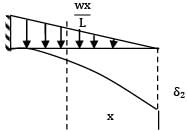
δ2 = 
δ3 = δ1 − δ2 = 
= 


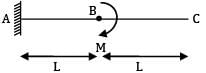
A beam of span 6m and of uniform flexural rigidity EI = 40000 kNm2 is subjected to a clockwise couple of 300 kNm at a distance of 4m from the left end. The deflection at the point of application of the couple is _______ mm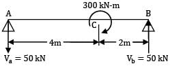 (A) 9.12(B) 9.72
Correct answer is option ''. Can you explain this answer?
A beam of span 6m and of uniform flexural rigidity EI = 40000 kNm2 is subjected to a clockwise couple of 300 kNm at a distance of 4m from the left end. The deflection at the point of application of the couple is _______ mm
(A) 9.12
(B) 9.72
|
|
Geetika Shah answered |
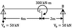
Taking moments about A, Vb × 6 = 300
Vb = 50 kN ↑
∴ Va = 50 kN ↓
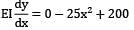
The B.M at any section distant x from A is given by,
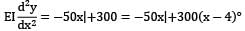
Integrating,
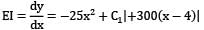
Integrating !gain,
EIy = 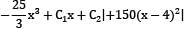
AT x = 0, t = 0
∴ C2 = 0
At x = 6, y = 0
∴ 0 = 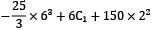
∴ C1 = 200
Deflection at C. Putting x = 4m, in the deflection equation,
EIyc = 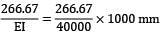
= 266.67
Max. deflection. This will occur in the larger segment. Equating the slope to zero, we get,
∴ x = 2√2 m
Putting x = 2√2 m in the deflection equation
EIymax =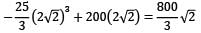
ymax = 
= 9.43 mm
Question_Type: 5


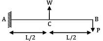
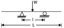
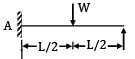
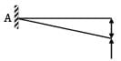
A beam ABC of length 3L has one support at the left end and the other support at a distance 2L from the left end. The beam carries a point load W at the right end. The deflection at the right end is- a)

- b)

- c)

- d)

Correct answer is option 'C'. Can you explain this answer?
A beam ABC of length 3L has one support at the left end and the other support at a distance 2L from the left end. The beam carries a point load W at the right end. The deflection at the right end is
a)
b)
c)
d)
|
|
Kiran Reddy answered |
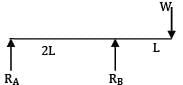
solving RA = 
RB = 3/2W
Deflection at C,
δc = 


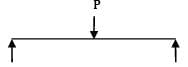
A beam simply supported at the ends carries a load W at the Centre, causing deflection y. If the depth of the section of the beam is doubled, the deflection at the Centre will be- a) y
- b) 1/2y
- c) 1/4 y
- d) 1/8y
Correct answer is option 'D'. Can you explain this answer?
A beam simply supported at the ends carries a load W at the Centre, causing deflection y. If the depth of the section of the beam is doubled, the deflection at the Centre will be
a)
y
b)
1/2y
c)
1/4 y
d)
1/8y
|
|
Sanvi Kapoor answered |
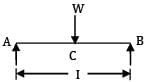
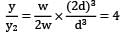
Deflection at C:
y =
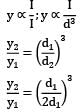
y2 = 1/8 × y
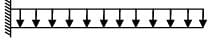
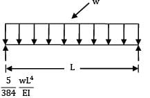
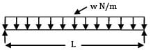
The maximum deflection of a cantilever of 10.0 m span, an EI = 200.0MN/m2 subjected to a distributed load of 8.0 kN/m is- a) 20 mm
- b) 50 mm
- c) 225 mm
- d) 500 mm
Correct answer is option 'B'. Can you explain this answer?
The maximum deflection of a cantilever of 10.0 m span, an EI = 200.0MN/m2 subjected to a distributed load of 8.0 kN/m is
a)
20 mm
b)
50 mm
c)
225 mm
d)
500 mm

|
Aarav Chauhan answered |
Maximum Deflection of Cantilever Beam
Given parameters:
- Span (L) = 10.0 m
- EI = 200.0 MN/m2
- Distributed load (w) = 8.0 kN/m
To determine the maximum deflection of the cantilever beam, we need to follow the steps below:
1. Calculate the reaction force (R) at the fixed end of the beam using the formula:
R = wL
Substituting the given values, we get:
R = 8.0 kN/m x 10.0 m = 80.0 kN
2. Determine the maximum deflection (δmax) using the formula:
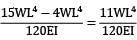
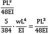
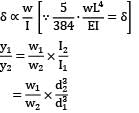
δmax = (5wL^4)/(384EI)
Substituting the given values and the calculated reaction force, we get:
δmax = (5 x 8.0 kN/m x (10.0 m)^4)/(384 x 200.0 MN/m2 x 80.0 kN)
δmax = 0.050 m or 50 mm (approximately)
Therefore, the correct answer is option B, which is 50 mm.
Given parameters:
- Span (L) = 10.0 m
- EI = 200.0 MN/m2
- Distributed load (w) = 8.0 kN/m
To determine the maximum deflection of the cantilever beam, we need to follow the steps below:
1. Calculate the reaction force (R) at the fixed end of the beam using the formula:
R = wL
Substituting the given values, we get:
R = 8.0 kN/m x 10.0 m = 80.0 kN
2. Determine the maximum deflection (δmax) using the formula:
δmax = (5wL^4)/(384EI)
Substituting the given values and the calculated reaction force, we get:
δmax = (5 x 8.0 kN/m x (10.0 m)^4)/(384 x 200.0 MN/m2 x 80.0 kN)
δmax = 0.050 m or 50 mm (approximately)
Therefore, the correct answer is option B, which is 50 mm.


A cantilever 3m long, and of symmetrical section 250 mm deep carries a uniformly distributed load of 30 kN/m run throughout together with a point of 80 kN at a section 1.2 m from fixed end. The deflection at the free end is __________ mm (Take E = 200 GPa, I = 54000 cm4)(A) 3.9(B) 4.5
Correct answer is option ''. Can you explain this answer?
A cantilever 3m long, and of symmetrical section 250 mm deep carries a uniformly distributed load of 30 kN/m run throughout together with a point of 80 kN at a section 1.2 m from fixed end. The deflection at the free end is __________ mm (Take E = 200 GPa, I = 54000 cm4)
(A) 3.9
(B) 4.5
|
|
Priyanka Sharma answered |
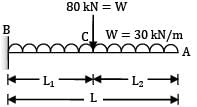
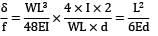
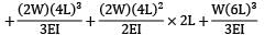
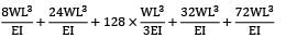
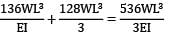
AB fixed at end B, Free at end A carrying a point load W at L1 from B end UDL of W throughout to length EI = flexural rigidity δ = deflection at free end
= 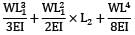
where, L1 = 1.2m, L2 = 1.8m, L = 3m,
W = 80 kN and W = 30 kN/m
EI = 200 × 106 kN/m2 × 54000 × 10−8 m4
= 108000 kNm2
δ = 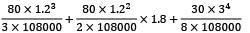
= 0.42666 × 10⁻³ + 0.96 × 10⁻³ + 2.8125 × 10−3
= 4.2 × 10⁻³m = 4.2 mm
Question_Type: 5
A cantilever of span L subjected to uniformly distributed gravity loading w/m is subjected to an upward force P at a distance L/2 from the free end. If the deflection at the free end of the beam is zero, (wL/P) is- a) 1.50
- b) 2.00
- c) 0.67
- d) 0.83
Correct answer is option 'D'. Can you explain this answer?
A cantilever of span L subjected to uniformly distributed gravity loading w/m is subjected to an upward force P at a distance L/2 from the free end. If the deflection at the free end of the beam is zero, (wL/P) is
a)
1.50
b)
2.00
c)
0.67
d)
0.83
|
|
Neha Joshi answered |
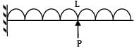
Deflection at free end due to vertical load
δ1 = 
Deflection at free end due to support P
δ2 = 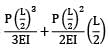
= 
∴ Deflection at free end is zero


= 0.83
The slope at the free end of a cantilever of length 1 m is 1°. If the cantilever carries uniformly distributed load over the whole length then the deflection at the free end will be- a) 1 cm
- b) 1.309 cm
- c) 2.618 cm
- d) 3.927 cm
Correct answer is option 'B'. Can you explain this answer?
The slope at the free end of a cantilever of length 1 m is 1°. If the cantilever carries uniformly distributed load over the whole length then the deflection at the free end will be
a)
1 cm
b)
1.309 cm
c)
2.618 cm
d)
3.927 cm
|
|
Lavanya Menon answered |
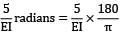
Δ = 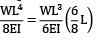
=  = 1.309cm
= 1.309cm If the deflection at the free end of a uniformly loaded cantilever beam is 15 mm and the slope of the deflection curve at the free end is 0.02 radian. then the length of the beam is- a) 0.8 m
- b) 1 m
- c) 1.2 m
- d) 1.5 m
Correct answer is option 'B'. Can you explain this answer?
If the deflection at the free end of a uniformly loaded cantilever beam is 15 mm and the slope of the deflection curve at the free end is 0.02 radian. then the length of the beam is
a)
0.8 m
b)
1 m
c)
1.2 m
d)
1.5 m
|
|
Avinash Sharma answered |
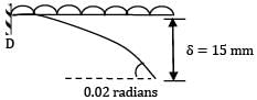
Deflection at free end, δ =  = 15 mm
= 15 mmSlope at free end, θ =  = 0.02
= 0.02∴ From the two
L = 1 m
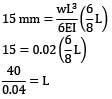
A horizontal steel rod ABC of diameter 50 mm and length 400 mm carrying a uniformly distributed load of 1.8 kN/m is simply supported at its ends A and C and is also supported at its mid-point B by its connection to a hanging vertical steel wire of 5 mm diameter and length 360 mm as shown in figure below. The deflection at point B is _________ mm (Take E = 2 × 10⁵ N/mm2). (A) 0.0076(B) 0.0082
Correct answer is option ''. Can you explain this answer?
A horizontal steel rod ABC of diameter 50 mm and length 400 mm carrying a uniformly distributed load of 1.8 kN/m is simply supported at its ends A and C and is also supported at its mid-point B by its connection to a hanging vertical steel wire of 5 mm diameter and length 360 mm as shown in figure below. The deflection at point B is _________ mm (Take E = 2 × 10⁵ N/mm2).
(A) 0.0076
(B) 0.0082
|
|
Priyanka Sharma answered |
Let T = Tension in the wire BD Deflection of B = Extension of the wire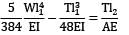
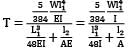
l1 = 400 mm, l2 = 360 mm,
W = 1.8 kN/m = 1.8 N/mm
D = 50 mm, I =  = 306796.875 mm
= 306796.875 mmd = 5 mm, A =  = 19.635 mm2
= 19.635 mm2T = 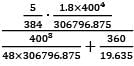 = 86.228 N
= 86.228 N∴ Deflection of B
= 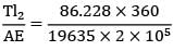 = 0.0079 mm
= 0.0079 mmQuestion_Type: 5
A prismatic simply supported beam carries a point load at mid-span section due to which a slope of 2° is produced at support sections. The slope at quarter span sections is- a) 1°
- b) 1.414°
- c) 1.5°
- d) 1.732°
Correct answer is option 'C'. Can you explain this answer?
A prismatic simply supported beam carries a point load at mid-span section due to which a slope of 2° is produced at support sections. The slope at quarter span sections is
a)
1°
b)
1.414°
c)
1.5°
d)
1.732°
|
|
Anita Menon answered |


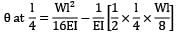
= 
= 
= 2 - 0.5 = 1.5°
A cantilever beam of uniform cross-section and length L is subjected to upward force W at mid-span and downward force P at the free end. For the deflection to be zero at the free end. W and P are related by- a) W = 2P
- b) W = 16P/5
- c) W = 3P
- d) W = 5P
Correct answer is option 'B'. Can you explain this answer?
A cantilever beam of uniform cross-section and length L is subjected to upward force W at mid-span and downward force P at the free end. For the deflection to be zero at the free end. W and P are related by
a)
W = 2P
b)
W = 16P/5
c)
W = 3P
d)
W = 5P
|
|
Zoya Sharma answered |
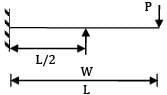
Deflection at free end due to load, p = 
Deflection at free end due to support load W
∴ The deflection at free end is zero

W = 16/5P
A simply supported beam of 10m span is carrying a load of 4.8kN at mid-span. If Young's modulus of elasticity (E) is 2 x 10⁸ kN/m2 and moment of inertia (I) is 20 cm4 , then the maximum deflection will be- a) 5.00 mm
- b) 2.50 mm
- c) 0.50 mm
- d) 0.25 mm
Correct answer is option 'B'. Can you explain this answer?
A simply supported beam of 10m span is carrying a load of 4.8kN at mid-span. If Young's modulus of elasticity (E) is 2 x 10⁸ kN/m2 and moment of inertia (I) is 20 cm4 , then the maximum deflection will be
a)
5.00 mm
b)
2.50 mm
c)
0.50 mm
d)
0.25 mm
|
|
Zoya Sharma answered |
Maximum deflection (y) = 
= 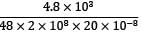
= 2.5mm
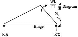
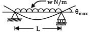
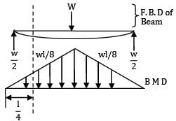
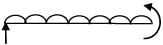
A prismatic beam of length L is simply supported at its ends and subjected to a total UDL of W spread over its entire span. It is then propped at its Centre to neutralize the deflection. The net B.M. at its Centre will be- a) WL
- b) WL/3
- c) WL/24
- d) WL/32
Correct answer is option 'D'. Can you explain this answer?
A prismatic beam of length L is simply supported at its ends and subjected to a total UDL of W spread over its entire span. It is then propped at its Centre to neutralize the deflection. The net B.M. at its Centre will be
a)
WL
b)
WL/3
c)
WL/24
d)
WL/32
|
|
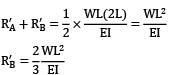
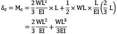
Anita Menon answered |
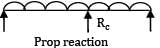
The propped reaction neutralize Downward deflection due to udl = upward Deflection due to support at C

∴ moment at C Mc = 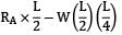
RA + RB + RC = W
∴ Rc =
RA + RB = W - 
Due to symmetry RA = RB = 
∴ Mc = 
= 
= 
=  (Clockwise)
(Clockwise) A simply supported beam of span L carries a UDL of w. N m−1. What is the magnitude of concentrated load to be supplied at the centre of this beam which would produce the same deflection as the UDL?- a) 3/8 wL
- b) wL/ 2
- c) 5 / 8 wL
- d) 7 / 8 wL
Correct answer is option 'C'. Can you explain this answer?
A simply supported beam of span L carries a UDL of w. N m−1. What is the magnitude of concentrated load to be supplied at the centre of this beam which would produce the same deflection as the UDL?
a)
3/8 wL
b)
wL/ 2
c)
5 / 8 wL
d)
7 / 8 wL
|
|
Sarita Yadav answered |
P = 5/8 ∙ w ∙ L
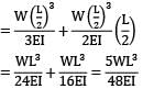
A cantilever beam of uniform EI has a span equal to ‘L’. An upward force W acts at the midpoint of the beam and a downward force P acts at the free end. In order that the deflection at the free end is zero, the relation between P and W should be- a) W =3P/2
- b) W = 2P
- c) W =16P/5
- d) W = 5P
Correct answer is option 'C'. Can you explain this answer?
A cantilever beam of uniform EI has a span equal to ‘L’. An upward force W acts at the midpoint of the beam and a downward force P acts at the free end. In order that the deflection at the free end is zero, the relation between P and W should be
a)
W =3P/2
b)
W = 2P
c)
W =16P/5
d)
W = 5P
|
|
Geetika Shah answered |
Upward deflection at B due to W
= 
= 
= 
Downward deflection due to P = 
∴ 
W= 


A cantilever of length 6 m is loaded as shown in the figure below. The maximum deflection in the beam isE = 200 MPa, I = 1 × 10⁻⁴ m−4, W = 1 kN.P1 = 3W P2 = 2W P3 = 1W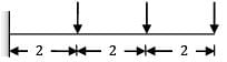
- a) 4.43 mm
- b) 2.28 mm
- c) 8.93 mm
- d) 12.68 mm
Correct answer is option 'C'. Can you explain this answer?
A cantilever of length 6 m is loaded as shown in the figure below. The maximum deflection in the beam is
E = 200 MPa, I = 1 × 10⁻⁴ m−4, W = 1 kN.
P1 = 3W P2 = 2W P3 = 1W
a)
4.43 mm
b)
2.28 mm
c)
8.93 mm
d)
12.68 mm

|
Torcia Education answered |
EI = 200 × 106 × 1 × 10−4 = 200,00 kNm2
Slope at free end
I = 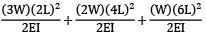
= 
= 
= 0.002 radian
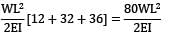
Deflection at free end
y = 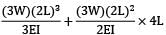
= 
= 
= 
= 0.00893 m = 8.93 mm
A simply supported beam of span ‘L’ carries a uniformly distributed load, 'w' per unit length over the entire span. The deflection at the center is 'y'. If the distributed load per unit length is doubled and also the depth of beam is doubled, the deflection at the center would be- a) 2 y
- b) 4 y
- c) 0.5 y
- d) 0.25 y
Correct answer is option 'D'. Can you explain this answer?
A simply supported beam of span ‘L’ carries a uniformly distributed load, 'w' per unit length over the entire span. The deflection at the center is 'y'. If the distributed load per unit length is doubled and also the depth of beam is doubled, the deflection at the center would be
a)
2 y
b)
4 y
c)
0.5 y
d)
0.25 y
|
|
Neha Joshi answered |
δmax = y
w2 = 2w
d2 = 2d
y2 = y / 4
 = 12.5%
 A horizontal beam (I = 8.616 × 107mm4) carries a uniformly distributed load of 50 kN over its length of 3m. The beam is supported by three vertical steel tie rods, each 1.80m long. One at each end and one at in the middle, the end rods having a diameter of 25mm and the centre rod a diameter of 30mm. The deflection of the centre of the beam is _________mm (Take E = 2 × 10⁵ N/mm2)(Take E = 2 × 10⁵ N/mm2)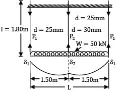 (A) 0.131(B) 0.139
Correct answer is option ''. Can you explain this answer?
A horizontal beam (I = 8.616 × 107mm4) carries a uniformly distributed load of 50 kN over its length of 3m. The beam is supported by three vertical steel tie rods, each 1.80m long. One at each end and one at in the middle, the end rods having a diameter of 25mm and the centre rod a diameter of 30mm. The deflection of the centre of the beam is _________mm (Take E = 2 × 10⁵ N/mm2)
(Take E = 2 × 10⁵ N/mm2)
(A) 0.131
(B) 0.139
|
|
Priyanka Sharma answered |

Area of each rod
= A1 =  = 490.87 mm2
= 490.87 mm2Area of the middle rod
= A2 =  = 706.86 mm2
= 706.86 mm2Let, P1 = Tension in each end rod
P2 = Tension in the middle rod
f1 = Stress in the rods
f2 = Stress in the middle rod
δ1 = Extension of each end rod
δ2 = Extension of the middle rod
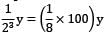
Deflection of the midpoint of the beam
δ2 − δ1 = 
EI(δ2 − δ1) = 

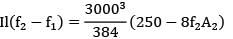
Deflection of beams
8.616 × 107 × 1800(f2 − f1)
= 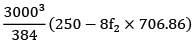
2205.696(f2 − f1) = 250 − 5654.88f2
2205.696f2 − 2205.696f1 = 250 − 5654.88f2
7860.576f2 − 2205.696f1 = 250 ⋯ ①
2f1A1 + f2A2 = 50
2f1(490.87) + f2 (706.86) = 50
981.74f, + 706.86f, = 50 ⋯ ②
From equation ① and ②,
7860.576f2 − 2205.696f1 = 5(981.74f,1 + 706.86f2)
7860.576f2 − 2205.696f1 = 4908.70f1 + 3534.3f2
4326.76f2 = 7114.396f1
∴ f2 = 1.644f1
Substituting in equation ②
981.74f1 + 706.86 × 1.644f1 = 50
2143.8178f1 = 50
f1 = 0.02332 kN/mm2 = 23.32 N/mm2
f2 = 1.644 × 23.32 = 38.33 N/mm2
Deflection of the midpoint of the beam
δ2 − δ1 = 
= 
=0.135 mm
Question_Type: 5
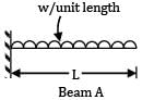
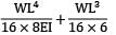
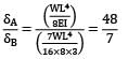
A simply supported beam 'A' of length L carries a central point load W. Another beam 'B' is loaded with a uniformly distributed load such that the total load on the beam is W. The ratio of maximum deflections between the beams A and B is- a) 5/8
- b) 8/5
- c) 5/4
- d) 4/5
Correct answer is option 'B'. Can you explain this answer?
A simply supported beam 'A' of length L carries a central point load W. Another beam 'B' is loaded with a uniformly distributed load such that the total load on the beam is W. The ratio of maximum deflections between the beams A and B is
a)
5/8
b)
8/5
c)
5/4
d)
4/5
|
|
Neha Joshi answered |
Maximum deflection of beam A,

Maximum deflection of beam B,
yB = 

= 
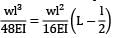
A uniform beam of length ‘L’ is simply and symmetrically supported to a span ‘l’ find the ratio L/l so that the upward deflection at each end equals the downward deflection at mid span, due to a concentrated point load at mid span.- a) 3/5
- b) 5/3
- c) 7/5
- d) 5/7
Correct answer is option 'B'. Can you explain this answer?
A uniform beam of length ‘L’ is simply and symmetrically supported to a span ‘l’ find the ratio L/l so that the upward deflection at each end equals the downward deflection at mid span, due to a concentrated point load at mid span.
a)
3/5
b)
5/3
c)
7/5
d)
5/7
|
|
Varun Kapoor answered |
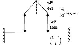
Deflection at midpoint = deflection at free end


determine the slope and deflection at a point in a beam is suitable for beams subjected to concentrated loads and can be extended to uniformly distributed loads Reason(R): Macaulay’s method is based upon the modification of moment of area method. This is applicable to a simple beam carrying a single concentrated load but by superposition, this method can be extended to cover any kind of loading.- a) both A and R are true and R is the correct explanation of A
- b) both A and R are true but R is not a correct explanation of A
- c) A is true but R is false
- d) A is false but R is true
Correct answer is option 'C'. Can you explain this answer?
determine the slope and deflection at a point in a beam is suitable for beams subjected to concentrated loads and can be extended to uniformly distributed loads Reason(R): Macaulay’s method is based upon the modification of moment of area method. This is applicable to a simple beam carrying a single concentrated load but by superposition, this method can be extended to cover any kind of loading.
a)
both A and R are true and R is the correct explanation of A
b)
both A and R are true but R is not a correct explanation of A
c)
A is true but R is false
d)
A is false but R is true
|
|
Priyanka Sharma answered |
Macaulay’s method is based on singularity function. It is applicable for prismatic beams only. While Mohr’s moment area method can be used for prismatic and non-prismatic beams.


A simply supported beam of span 4m subjected to a point load of 4 kN at a distance of 3m from the left support. The maximum slope occurs- a) At the left support
- b) At right support
- c) At mid-span
- d) Under the point load
Correct answer is option 'B'. Can you explain this answer?
A simply supported beam of span 4m subjected to a point load of 4 kN at a distance of 3m from the left support. The maximum slope occurs
a)
At the left support
b)
At right support
c)
At mid-span
d)
Under the point load
|
|
Zoya Sharma answered |
The load is closer to right support; the slope is max at right.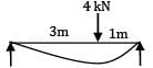
Other parameters being unchanged, if the span of a cantilever carrying end point load is doubled, the maximum slope is increased by- a) 2 times
- b) 4 times
- c) 8 times
- d) 16 times
Correct answer is option 'B'. Can you explain this answer?
Other parameters being unchanged, if the span of a cantilever carrying end point load is doubled, the maximum slope is increased by
a)
2 times
b)
4 times
c)
8 times
d)
16 times
|
|
Avinash Sharma answered |
(i) 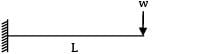
θmax |1 = 
(ii) 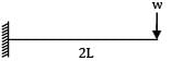
θmax |2 = 
θmax |2 = 4 × θmax|1
A point load ‘W’ is acting at the mid-span of a cantilever of length ‘L’. If the free end is supported on a rigid prop, the reaction of the prop is- a) 5W/13
- b) 5W/11
- c) 5W/16
- d) 7W/9
Correct answer is option 'C'. Can you explain this answer?
A point load ‘W’ is acting at the mid-span of a cantilever of length ‘L’. If the free end is supported on a rigid prop, the reaction of the prop is
a)
5W/13
b)
5W/11
c)
5W/16
d)
7W/9
|
|
Amit Sharma answered |
yb = 
ya = 
Equating upward and downward deflection

VB = 
If the actual beam has both ends fixed, then the ends of the conjugate beam will be- a) Fixed at both ends
- b) Free at both ends
- c) Fixed at one end, free at other end
- d) Hinged at one end, free at other end
Correct answer is option 'B'. Can you explain this answer?
If the actual beam has both ends fixed, then the ends of the conjugate beam will be
a)
Fixed at both ends
b)
Free at both ends
c)
Fixed at one end, free at other end
d)
Hinged at one end, free at other end
|
|
Bhaskar Mukherjee answered |
Explanation:
When a beam is fixed at both ends, it means that the beam is restrained from both translation and rotation at those points. In other words, the supports at the ends provide both vertical and horizontal reactions, as well as moments to resist any applied loads.
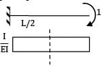
The conjugate beam is a mathematical tool used in structural analysis to determine the deflection and slope of a beam. It is derived from the original beam by following a set of rules:
1. The length of the conjugate beam is the same as the original beam.
2. The supports of the conjugate beam are located at the same positions as the original beam.
3. The reactions at the supports of the conjugate beam are equal to the slopes of the original beam at those points.
4. The loads on the conjugate beam are equal to the bending moments of the original beam divided by the length of the beam.
In this case, the actual beam has both ends fixed:
When a beam has both ends fixed, it means that the ends are restrained from translation and rotation. The supports at the ends provide both vertical and horizontal reactions, as well as moments to resist any applied loads.
Conjugate beam for a beam with both ends fixed:
When we apply the rules of the conjugate beam, we find that the ends of the conjugate beam will be free at both ends. This means that the supports of the conjugate beam will not provide any reactions or moments. The conjugate beam will be free to translate and rotate at both ends.
Reasoning:
The fixed support at the ends of the actual beam provides both vertical and horizontal reactions, as well as moments to resist any applied loads. However, when we convert the actual beam to its conjugate beam, the supports of the conjugate beam do not provide any reactions or moments. This is because the conjugate beam is a mathematical tool used to determine the deflection and slope of the original beam, and it does not represent the actual physical supports of the beam.
Therefore, the ends of the conjugate beam will be free at both ends (option B).
When a beam is fixed at both ends, it means that the beam is restrained from both translation and rotation at those points. In other words, the supports at the ends provide both vertical and horizontal reactions, as well as moments to resist any applied loads.
The conjugate beam is a mathematical tool used in structural analysis to determine the deflection and slope of a beam. It is derived from the original beam by following a set of rules:
1. The length of the conjugate beam is the same as the original beam.
2. The supports of the conjugate beam are located at the same positions as the original beam.
3. The reactions at the supports of the conjugate beam are equal to the slopes of the original beam at those points.
4. The loads on the conjugate beam are equal to the bending moments of the original beam divided by the length of the beam.
In this case, the actual beam has both ends fixed:
When a beam has both ends fixed, it means that the ends are restrained from translation and rotation. The supports at the ends provide both vertical and horizontal reactions, as well as moments to resist any applied loads.
Conjugate beam for a beam with both ends fixed:
When we apply the rules of the conjugate beam, we find that the ends of the conjugate beam will be free at both ends. This means that the supports of the conjugate beam will not provide any reactions or moments. The conjugate beam will be free to translate and rotate at both ends.
Reasoning:
The fixed support at the ends of the actual beam provides both vertical and horizontal reactions, as well as moments to resist any applied loads. However, when we convert the actual beam to its conjugate beam, the supports of the conjugate beam do not provide any reactions or moments. This is because the conjugate beam is a mathematical tool used to determine the deflection and slope of the original beam, and it does not represent the actual physical supports of the beam.
Therefore, the ends of the conjugate beam will be free at both ends (option B).


Chapter doubts & questions for Deflection of Beams - 6 Months Preparation for GATE Civil Engg 2025 is part of Civil Engineering (CE) exam preparation. The chapters have been prepared according to the Civil Engineering (CE) exam syllabus. The Chapter doubts & questions, notes, tests & MCQs are made for Civil Engineering (CE) 2025 Exam. Find important definitions, questions, notes, meanings, examples, exercises, MCQs and online tests here.
Chapter doubts & questions of Deflection of Beams - 6 Months Preparation for GATE Civil Engg in English & Hindi are available as part of Civil Engineering (CE) exam.
Download more important topics, notes, lectures and mock test series for Civil Engineering (CE) Exam by signing up for free.
6 Months Preparation for GATE Civil Engg
488 videos|1261 docs|878 tests
|
|
© EduRev
|
Education Revolution
|


|


Signup to see your scores
go up
within 7 days!
within 7 days!
Takes less than 10 seconds to signup