


All Exams >
Computer Science Engineering (CSE) >
6 Months Preparation for GATE CSE >
All Questions
All questions of Sequential Circuits for Computer Science Engineering (CSE) Exam
A frequency counter needs to measure a frequency of 30 Hz. If the gating time is 2 seconds then determine how many times the trigger level has been crossed?- a)30
- b)60
- c)15
- d)50
Correct answer is option 'B'. Can you explain this answer?
A frequency counter needs to measure a frequency of 30 Hz. If the gating time is 2 seconds then determine how many times the trigger level has been crossed?
a)
30
b)
60
c)
15
d)
50
|
|
Swara Basak answered |
To determine the number of times the trigger level has been crossed, we need to consider the frequency of the signal and the gating time.
Frequency of the signal: 30 Hz
Gating time: 2 seconds
To calculate the number of times the trigger level has been crossed, we can use the formula:
Number of crossings = Frequency * Gating time
Let's plug in the given values:
Number of crossings = 30 Hz * 2 seconds
Number of crossings = 60
Hence, the correct answer is option 'B' - 60.
Explanation:
Let's break down the calculation step by step:
1. Frequency of the signal: 30 Hz
This means that the signal completes 30 cycles in one second.
2. Gating time: 2 seconds
The gating time is the duration for which the frequency counter counts the number of crossings. In this case, the gating time is 2 seconds.
3. Number of crossings = Frequency * Gating time
Substituting the values, we get:
Number of crossings = 30 Hz * 2 seconds
Number of crossings = 60
Therefore, the trigger level has been crossed 60 times within the given gating time of 2 seconds.
Note: It is important to understand that the frequency counter counts the number of crossings of the signal above the trigger level within the specified gating time. This count can be used to determine the frequency of the signal accurately.

A mod–n counter using a synchronous binary up–counter with synchronous clear input is shown in the figure. The value of n is_________.

Correct answer is '7'. Can you explain this answer?
A mod–n counter using a synchronous binary up–counter with synchronous clear input is shown in the figure. The value of n is_________.

|
Riverdale Learning Institute answered |
Concept:
 It is an active low signal. It is activated when
  =0 and it resets the FF.
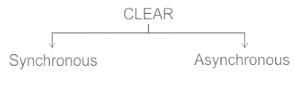
CLR: It is an active high signal. It is activated when CLR = 1 and it Resets the FF.
It is an active low signal. It is activated when =0 and it resets the FF.CLR: It is an active high signal. It is activated when CLR = 1 and it Resets the FF.
- Synchronous: Synchronous clear is synchronized with the clock. It waits for a clock pulse to Reset FF output.
- Asynchronous: Asynchronous Clear is not synchronized with the clock. It does not wait for a clock pulse to Reset FF output.
Application:
From given sequential circuit:
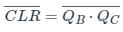
When both QB & QC equal to 1 then =0. Otherwise
  = 1
= 1
Now,
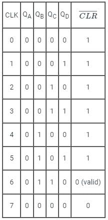
Since it is given that the counter have synchronous clear input, the output of the counter will reset at the 7th clock pulse.
∴ The mod of the counter, n = 7
From given sequential circuit:
When both QB & QC equal to 1 then
=0. Otherwise = 1Now,
Since it is given that the counter have synchronous clear input, the output of the counter will reset at the 7th clock pulse.
∴ The mod of the counter, n = 7
Synchronous counter is a type of ____________- a)SSI counters
- b)LSI counters
- c)MSI counters
- d)VLSI counters
Correct answer is option 'C'. Can you explain this answer?
Synchronous counter is a type of ____________
a)
SSI counters
b)
LSI counters
c)
MSI counters
d)
VLSI counters
|
|
Sudhir Patel answered |
Synchronous Counter is a Medium Scale Integrated (MSI). In Synchronous Counters, the clock pulse is supplied to all the flip-flops simultaneously.
The output of latches will remain in set/reset untill ___________- a)The trigger pulse is given to change the state
- b)Any pulse given to go into previous state
- c)They don’t get any pulse more
- d)The pulse is edge-triggered
Correct answer is option 'A'. Can you explain this answer?
The output of latches will remain in set/reset untill ___________
a)
The trigger pulse is given to change the state
b)
Any pulse given to go into previous state
c)
They don’t get any pulse more
d)
The pulse is edge-triggered
|
|
Sarthak Desai answered |
C) They are externally reset
Which property is NOT considered in latches?- a)Output of the latches changes as we change the input.
- b)changes as we change the input.
- c)Latches are edge triggered.
- d)Latches are fast.
Correct answer is option 'C'. Can you explain this answer?
Which property is NOT considered in latches?
a)
Output of the latches changes as we change the input.
b)
changes as we change the input.
c)
Latches are edge triggered.
d)
Latches are fast.
|
|
Sudhir Patel answered |
- Latches are level-triggered (outputs can change as soon as the inputs changes)
- Flip-Flop is edge-triggered (only changes state when a control signal goes from high to low or low to high).
- Edge triggering is a type of triggering that allows a circuit to become active at the positive edge or the negative edge of the clock signal.
- Level triggering is a type of triggering that allows a circuit to become active when the clock pulse is on a particular level.
Latch is a device with ___________
- a)One stable state
- b)Infinite stable states
- c)Three stable state
- d)Two stable state
Correct answer is option 'D'. Can you explain this answer?
Latch is a device with ___________
a)
One stable state
b)
Infinite stable states
c)
Three stable state
d)
Two stable state
|
|
Kiran Reddy answered |
Introduction:
A latch is a fundamental digital circuit that is used to store and remember a binary value. It is a sequential logic device, which means that its output depends not only on the current input but also on the previous inputs. A latch can have multiple stable states, depending on the type of latch and its configuration.
Explanation:
There are various types of latches, such as SR latch, D latch, JK latch, and T latch. Each latch has a different number of stable states.
1. SR Latch:
An SR (Set-Reset) latch has two stable states, represented by the inputs S (Set) and R (Reset). When S=0 and R=0, the latch holds its previous state. When S=0 and R=1, the latch is reset and its output is 0. When S=1 and R=0, the latch is set and its output is 1. If both S and R are 1, the latch enters an invalid state.
2. D Latch:
A D latch has one stable state. It has a single input D (Data) and an enable input E. When E=1, the latch stores the value of D at its output. When E=0, the latch holds its previous state.
3. JK Latch:
A JK latch has two stable states. It has two inputs J (Jack) and K (Kill). When J=0 and K=0, the latch holds its previous state. When J=0 and K=1, the latch is reset. When J=1 and K=0, the latch is set. When J=1 and K=1, the latch toggles its state.
4. T Latch:
A T latch has two stable states. It has a single input T (Toggle) and an enable input E. When E=1, the latch toggles its state whenever T=1. When E=0, the latch holds its previous state.
Conclusion:
In conclusion, a latch can have different numbers of stable states depending on its type and configuration. While some latches have one stable state, others can have two or more stable states. It is important to understand the behavior of different types of latches in order to design and analyze digital circuits effectively.
When a high is applied to the Set line of an SR latch, then ___________- a)Q output goes high
- b)Q’ output goes high
- c)Q output goes low
- d)Both Q and Q’ go high
Correct answer is option 'A'. Can you explain this answer?
When a high is applied to the Set line of an SR latch, then ___________
a)
Q output goes high
b)
Q’ output goes high
c)
Q output goes low
d)
Both Q and Q’ go high
|
|
Eesha Bhat answered |
S input of an SR latch is directly connected to the output Q. So when a high is applied Q output goes high and Q’ low.
The basic latch consists of ___________- a)Two inverters
- b)Two comparators
- c)Two amplifiers
- d)Two adders
Correct answer is option 'A'. Can you explain this answer?
The basic latch consists of ___________
a)
Two inverters
b)
Two comparators
c)
Two amplifiers
d)
Two adders
|
|
Eesha Bhat answered |
The basic latch consists of two inverters. It is in the sense that if the output Q = 0 then the second output Q’ = 1 and vice versa.
Which of the following is not a sequential circuit?- a)flip-flop
- b)counter
- c)shift register
- d)multiplexer
Correct answer is option 'D'. Can you explain this answer?
Which of the following is not a sequential circuit?
a)
flip-flop
b)
counter
c)
shift register
d)
multiplexer
|
|
Sudhir Patel answered |
- Combinational logic is a type of digital logic that is implemented by Boolean circuits, where the output is a pure function of the present input only.
- Sequential logic is a type of digital logic in which the output depends not only on the present input but also on the history of the output.
- Sequential logic has memory while combinational logic does not.
- Flip-flop, counter, and shift registers are sequential circuits whereas multiplexer, decoder, and encoder act like combinational circuits.
A Shift register in which the output of the last flip-flop is connected to the input of the first flip-flop- a)BCD counter
- b)Parallel counter
- c)Ripple counter
- d)Ring counter
Correct answer is option 'D'. Can you explain this answer?
A Shift register in which the output of the last flip-flop is connected to the input of the first flip-flop
a)
BCD counter
b)
Parallel counter
c)
Ripple counter
d)
Ring counter
|
|
Nisha Das answered |
Introduction:
A shift register is a sequential logic circuit that can store and shift data. It consists of a series of flip-flops connected in a chain. The output of one flip-flop is connected to the input of the next flip-flop, allowing the data to be shifted or circulated within the register. There are different types of shift registers, and one of them is a ring counter.
Ring Counter:
A ring counter is a type of shift register in which the output of the last flip-flop is connected to the input of the first flip-flop, forming a closed loop or a ring structure. This configuration enables the data to circulate continuously within the register. Each flip-flop in the ring counter represents a different state or value, and the circulating data sequence determines the current state of the counter.
Working of a Ring Counter:
1. Initially, all the flip-flops in the ring counter are reset to a known state. This can be achieved by applying a synchronous reset signal to all the flip-flops simultaneously.
2. When a clock signal is applied, it causes the data to be shifted from one flip-flop to the next. The last flip-flop's output is connected to the first flip-flop's input, resulting in the circulating behavior.
3. As the data circulates, each flip-flop represents a different state or value. The number of flip-flops determines the number of states the ring counter can represent.
4. The output of each flip-flop can be used to drive external circuitry or as inputs to other digital logic circuits.
5. The ring counter can be designed to have a specific sequence of states, depending on the desired application. For example, a 4-bit ring counter can be designed to represent a sequence of binary numbers from 0000 to 1111, forming a 4-bit binary counter.
Advantages and Applications:
- The ring counter is simple to design and implement using flip-flops.
- It is useful in applications where a specific sequence of states or values needs to be generated cyclically.
- Ring counters find applications in areas such as digital clocks, frequency dividers, sequence generators, and control circuitry.
In conclusion, a ring counter is a shift register in which the output of the last flip-flop is connected to the input of the first flip-flop, forming a closed loop. This configuration allows the data to circulate continuously within the register, representing different states or values. A ring counter is advantageous in applications that require a cyclic sequence of states or values.
Master-slave configuration is used in FF to- a)Increase its clocking rate
- b)Reduces power dissipation
- c)Eliminates race around condition
- d)Improves its reliability
Correct answer is option 'C'. Can you explain this answer?
Master-slave configuration is used in FF to
a)
Increase its clocking rate
b)
Reduces power dissipation
c)
Eliminates race around condition
d)
Improves its reliability
|
|
Sudhir Patel answered |
Race around condition:
For JK flip-flop if J, K, and Clock are equal to 1 the state of flip-flop keeps on toggling which leads to uncertainty in determining the output of the flip-flop. This problem is called Race around the condition.
For JK flip-flop if J, K, and Clock are equal to 1 the state of flip-flop keeps on toggling which leads to uncertainty in determining the output of the flip-flop. This problem is called Race around the condition.
This can be eliminated by using the following methods.
- Increasing the delay of flip-flop
- Use of edge-triggered flip-flop
- Use of master-slave JK flip flop
The Master-slave configuration is used in a flipflop to eliminate the race around condition but not to store two bits of information.
When both inputs of SR latches are high, the latch goes ___________- a)Unstable
- b)Stable
- c)Metastable
- d)Bistable
Correct answer is option 'C'. Can you explain this answer?
When both inputs of SR latches are high, the latch goes ___________
a)
Unstable
b)
Stable
c)
Metastable
d)
Bistable
|
|
Rahul Chavan answered |
The correct answer is option 'C' - Metastable.
Explanation:
An SR latch is a basic memory element in digital circuits that stores one bit of information. It has two inputs - S (Set) and R (Reset). When both inputs are high (S = 1, R = 1), it creates a condition called "metastability."
Metastability is a state in digital circuits where the output of a latch becomes uncertain or unpredictable. In this state, the latch may settle into either a logic high or a logic low state, and the output may oscillate between these states or remain in an indeterminate state for an unknown period of time.
Several factors can contribute to metastability in an SR latch:
1. Setup and Hold Time Violation: The inputs S and R need to be stable for a certain amount of time before and after the clock signal transitions. If the setup and hold time requirements are not met, the latch can enter a metastable state.
2. Signal Skew: If the signals S and R arrive at different times due to variations in propagation delay, it can result in metastability.
3. Noise: External noise or glitches on the inputs can cause the SR latch to enter a metastable state.
4. Power Supply Variation: Variations in the power supply voltage can also contribute to metastability.
When a latch is in a metastable state, it can eventually settle into a stable state, either high or low, but the time taken to settle is unpredictable. The settling time can vary from nanoseconds to milliseconds, depending on various factors.
To avoid the issues caused by metastability, additional circuitry is used in practical designs. One common solution is to use multiple stages of latches or flip-flops to capture the output of a metastable latch and reduce the probability of propagating the metastable state further.
In conclusion, when both inputs of an SR latch are high, it enters a metastable state where the output becomes uncertain and can oscillate or remain in an indeterminate state. Metastability is an undesirable condition in digital circuits, and proper design techniques are required to mitigate its effects.
A frequency counter needs to measure a frequency of 40 Hz. If the gating time is 2 seconds then determine percentage accuracy of the counter, taking into account the gating error?- a)96.5
- b)98.75
- c)99.1
- d)98
Correct answer is option 'B'. Can you explain this answer?
A frequency counter needs to measure a frequency of 40 Hz. If the gating time is 2 seconds then determine percentage accuracy of the counter, taking into account the gating error?
a)
96.5
b)
98.75
c)
99.1
d)
98
|
|
Sudhir Patel answered |
Concept:
digital frequency counters that use a direct counting approach count the number of times the input signal crosses a given trigger voltage (and in a given direction, e.g. moving from negative to positive) in a given time. This time is known as gate time.
The frequency is equal to the number of crossings of the trigger level in one second. Therefore
Frequency(f)=Triggerl evel crossing (N)/Gatetime(t)
Percentage accuracy of the counter= (N−1/N) × 100
Calculation:
Given;
Gate time = 2 sec
Frequency = 40 Hz
Then;
Frequency(f)=Trigger level crossing(N)/Gatetime(t)
Trigger level crossing (N) = Frequency (f) ×Gate time(t)=40 × 2 = 80
Hence;
Percentageaccuracyofthecounter=(N−1/N) × 100= (80−1/80) × 100 = 98.75
Hence, option b is the correct answer.
How many Flip flops circuits are needed to divide by 16?- a)Two
- b)Four
- c)Eight
- d)Sixteen
Correct answer is option 'B'. Can you explain this answer?
How many Flip flops circuits are needed to divide by 16?
a)
Two
b)
Four
c)
Eight
d)
Sixteen
|
|
Arnab Kapoor answered |
Introduction:
To divide by 16, we need to design a circuit that can count up to 16 and then reset back to 0. This can be achieved using a counter circuit with flip-flops.
Explanation:
A counter circuit is a sequential circuit that counts the number of input pulses and generates an output based on the count. In this case, we need to count up to 16, which can be represented in binary as 10000.
Binary representation:
The binary representation of 16 is 10000, which requires 5 bits to represent. Each bit represents the state of a flip-flop in the counter circuit.
Flip-flop circuit:
A flip-flop is a basic building block of sequential circuits. It can store one bit of information and has two stable states, 0 and 1. In this case, we need 5 flip-flops to represent the 5 bits of the binary number.
Divide by 16:
To divide by 16, we need to count up to 16 and then reset back to 0. This means that the counter circuit needs to have 16 states. Since each flip-flop can represent 2 states (0 and 1), we need a total of 4 flip-flops to represent 16 states.
Example:
Let's consider a 4-bit counter circuit using flip-flops. The states of the flip-flops are represented as Q3, Q2, Q1, and Q0. When the circuit is reset, all flip-flops are set to 0. As the clock signal is applied, the circuit counts up from 0 to 15 (represented in binary as 0000 to 1111), and then resets back to 0.
Conclusion:
In order to divide by 16, we need 4 flip-flops in the counter circuit. Each flip-flop represents one bit of the binary number. This allows us to count up to 16 and then reset back to 0, effectively dividing the input by 16. Therefore, the correct answer is option B - Four flip-flops.
______ is commonly used to interface output devices.- a)Buffer
- b)Pulse generator
- c)Accumulator
- d)Latch
Correct answer is option 'D'. Can you explain this answer?
______ is commonly used to interface output devices.
a)
Buffer
b)
Pulse generator
c)
Accumulator
d)
Latch
|
|
Sudhir Patel answered |
- Latches are memory devices and can store one bit of data for as long as the device is powered.
- As the name suggests, latches are used to "latch onto" information and hold it in place.
- Latches are very similar to flip-flops, but are not synchronous devices, and do not operate on clock edges as flip-flops do.
- The reason for using the latch in an output port is simple, we do not want to lose the result of any operation.
- So, in order to not lose it, we use a latch, so that it holds the information as long as new information is overwritten onto it.
- An 8-bit latch can be used to interface the output of a microprocessor to other devices.
- The 74LS373 octal latch and the 74LS374 octal D flip-flop are popular microprocessor interface chips.
Note: Tristate buffer is commonly used to interface input devices.
The logic circuits whose outputs at any instant of time depends only on the present input but also on the past outputs are called ________________- a)Combinational circuits
- b)Sequential circuits
- c)Latches
- d)Flip-flops
Correct answer is option 'B'. Can you explain this answer?
The logic circuits whose outputs at any instant of time depends only on the present input but also on the past outputs are called ________________
a)
Combinational circuits
b)
Sequential circuits
c)
Latches
d)
Flip-flops
|
|
Samridhi Ahuja answered |
Sequential circuits are logic circuits whose outputs not only depend on the present input but also on the past outputs. These circuits have memory elements, such as flip-flops or latches, which store and retain information about previous inputs and outputs.
Combinational Circuits:
Combinational circuits, on the other hand, are logic circuits whose outputs depend solely on the present input values. These circuits do not have any memory elements and their outputs are determined by the combination of the input values at a given instant.
Sequential Circuits:
Sequential circuits are designed to have memory elements, allowing them to store and remember past outputs. These circuits can be used to create systems that have memory and can perform tasks based on the history of inputs.
Memory Elements:
The memory elements in sequential circuits are typically flip-flops or latches. These components can store a single bit of information and have two stable states (0 and 1). They can retain their current state until they receive a clock signal or a control signal to change their state.
Flip-Flops:
Flip-flops are the most commonly used memory elements in sequential circuits. They have two stable states, which are represented by the logic levels 0 and 1. The state of a flip-flop can be changed by applying appropriate inputs and clock signals.
Latches:
Latches are another type of memory element used in sequential circuits. They can store one bit of information and have two stable states, similar to flip-flops. However, latches are level-sensitive and can change their state as long as the input conditions are met.
Dependence on Past Outputs:
The key characteristic of sequential circuits is their dependence on past outputs. The current output of a sequential circuit is influenced by the present input as well as the previous outputs. This allows these circuits to perform tasks that require memory or require the consideration of past inputs.
In conclusion, the logic circuits whose outputs depend not only on the present input but also on the past outputs are called sequential circuits. These circuits utilize memory elements like flip-flops or latches to store and remember past outputs, enabling them to perform tasks that require memory or history-dependent operations.
The truth table for an S-R flip-flop has how many VALID entries?- a)1
- b)2
- c)3
- d)4
Correct answer is option 'C'. Can you explain this answer?
The truth table for an S-R flip-flop has how many VALID entries?
a)
1
b)
2
c)
3
d)
4
|
|
Eesha Bhat answered |
The SR flip-flop actually has three inputs, Set, Reset and its current state. The Invalid or Undefined State occurs at both S and R being at 1.
The parallel outputs of a counter circuit represent the _____________- a)Parallel data word
- b)Clock frequency
- c)Counter modulus
- d)Clock count
Correct answer is option 'D'. Can you explain this answer?
The parallel outputs of a counter circuit represent the _____________
a)
Parallel data word
b)
Clock frequency
c)
Counter modulus
d)
Clock count
|
|
Sudhir Patel answered |
The parallel outputs of a counter circuit represent the clock count. A counter counts the number of times an event takes place in accordance to the clock pulse.
_________ only allows for one master and one slave and is limited to distances of up to 15 meters.- a)RS-422
- b)RS-485
- c)RS-232
- d) None of the above.
Correct answer is option 'C'. Can you explain this answer?
_________ only allows for one master and one slave and is limited to distances of up to 15 meters.
a)
RS-422
b)
RS-485
c)
RS-232
d)
None of the above.
|
|
Samarth Ghosh answered |
Understanding RS-232
RS-232 is a standard for serial communication that is widely used in computer and telecommunications equipment.
Key Features of RS-232:
Conclusion
In summary, RS-232 is a simple and straightforward interface for serial communication but is limited by its single master-slave setup and short distance capabilities. This makes it less suitable for modern networking applications where multiple devices need to communicate over longer distances, which is why protocols like RS-485 or RS-422 are often preferred in such scenarios.
RS-232 is a standard for serial communication that is widely used in computer and telecommunications equipment.
Key Features of RS-232:
- Single Master-Slave Configuration: RS-232 allows for only one master device (usually a computer) to communicate with one slave device (like a modem or printer). This means that the communication is not suited for multi-device networks.
- Distance Limitations: The maximum distance for reliable communication using RS-232 is typically up to 15 meters (about 50 feet). Beyond this distance, the signal may degrade, leading to data loss or errors.
- Voltage Levels: RS-232 uses specific voltage levels to represent binary data. A voltage between +3V to +15V represents a logical “0”, while -3V to -15V represents a logical “1”. This differential in voltage helps in maintaining signal integrity over short distances.
- Connector Types: RS-232 commonly uses DB9 or DB25 connectors, which are standard connectors in serial communication.
- Lower Data Rates: RS-232 typically supports lower baud rates, usually up to 115200 bps, which is adequate for many applications but not suitable for high-speed data transfer.
Conclusion
In summary, RS-232 is a simple and straightforward interface for serial communication but is limited by its single master-slave setup and short distance capabilities. This makes it less suitable for modern networking applications where multiple devices need to communicate over longer distances, which is why protocols like RS-485 or RS-422 are often preferred in such scenarios.
Three T flip flops are connected to form a counter. The maximum states possible for the counter will be:- a)5
- b)3
- c)8
- d)7
Correct answer is option 'C'. Can you explain this answer?
Three T flip flops are connected to form a counter. The maximum states possible for the counter will be:
a)
5
b)
3
c)
8
d)
7
|
|
Swati Kaur answered |
To understand why the maximum states possible for the counter formed by three T flip flops is 8, let's break it down step by step.
T flip flops are a type of flip flop that toggle its output based on the input signal. Each T flip flop has one input (T) and two outputs (Q and Q'). The Q output represents the current state of the flip flop, while the Q' output represents the complement of the Q output.
A counter is a sequential circuit that counts the number of events or cycles. In this case, we are using T flip flops to build the counter. Each T flip flop represents one bit of the counter, and the number of states the counter can have is determined by the number of bits.
In a binary system, the number of states for n bits is 2^n. Therefore, for a counter formed by three T flip flops, the number of states can be calculated as 2^3 = 8.
To understand why it is 8, let's look at the binary representation of the states:
- State 0: Q2 Q1 Q0 = 000
- State 1: Q2 Q1 Q0 = 001
- State 2: Q2 Q1 Q0 = 010
- State 3: Q2 Q1 Q0 = 011
- State 4: Q2 Q1 Q0 = 100
- State 5: Q2 Q1 Q0 = 101
- State 6: Q2 Q1 Q0 = 110
- State 7: Q2 Q1 Q0 = 111
As you can see, with three T flip flops, we can represent 8 different states. The counter will cycle through these states in a specific sequence determined by the clock signal and the inputs to the T flip flops.
Therefore, the correct answer is option C) 8.
An eight-bit binary ripple UP counter with a modulus of 256 is holding the count 01111111. What will be the count after 135 clock pulses?- a)0000 0101
- b)1111 1001
- c)0000 0110
- d)0000 0111
Correct answer is option 'C'. Can you explain this answer?
An eight-bit binary ripple UP counter with a modulus of 256 is holding the count 01111111. What will be the count after 135 clock pulses?
a)
0000 0101
b)
1111 1001
c)
0000 0110
d)
0000 0111
|
|
Sudhir Patel answered |
01111111 → 127
After 135 clock cycles, we will get
127 + 135 = 262
∴ The total number of clock pulses will be 262
As the modulus is 256,
After 256 clock pulses, the sequence will repeat.
262 = 256 + 6
∴ 00 00 00 00
257 → 00 00 00 01
258 → 00 00 00 10
259 → 00 00 00 11
260 → 00 00 01 00
261 → 00 00 01 01
262 → 00 00 01 10
The circuits of NOR based S-R latch classified as asynchronous sequential circuits, why?- a)Because of inverted outputs
- b)Because of triggering functionality
- c)Because of cross-coupled connection
- d)Because of inverted outputs & triggering functionality
Correct answer is option 'C'. Can you explain this answer?
The circuits of NOR based S-R latch classified as asynchronous sequential circuits, why?
a)
Because of inverted outputs
b)
Because of triggering functionality
c)
Because of cross-coupled connection
d)
Because of inverted outputs & triggering functionality
|
|
Palak Shah answered |
C) Because of cross-coupled connection.
The circuits of NOR based S-R latch are classified as asynchronous sequential circuits because of their cross-coupled connection. In this configuration, the output of one NOR gate is connected to the input of the other NOR gate, and vice versa. This cross-coupling creates a feedback loop, which allows the latch to store and remember its previous state.
The cross-coupled connection is what gives the NOR based S-R latch its sequential functionality. It allows the latch to maintain its state even after the input signals have changed. This makes it suitable for applications that require memory storage and sequential operations.
The inverted outputs (option d) are a consequence of the NOR gate's logic operation, but they are not the main reason why the NOR based S-R latch is classified as an asynchronous sequential circuit.
Two stable states of latches are ___________- a)Astable & Monostable
- b)Low input & high output
- c)High output & low output
- d)Low output & high input
Correct answer is option 'C'. Can you explain this answer?
Two stable states of latches are ___________
a)
Astable & Monostable
b)
Low input & high output
c)
High output & low output
d)
Low output & high input
|
|
Eesha Bhat answered |
A latch has two stable states, following the principle of Bistable Multivibrator. There are two stable states of latches and these states are high-output and low-output.
For the circuit shown, the counter state (Q1Q0) follows the sequence

- a)00, 01,10, 11,00 ....
- b)00, 01, 10, 00, 01 ....
- c)00, 01, 11, 00, 01 ....
- d)00,10, 11,00, 10 ....
Correct answer is option 'B'. Can you explain this answer?
For the circuit shown, the counter state (Q1Q0) follows the sequence
a)
00, 01,10, 11,00 ....
b)
00, 01, 10, 00, 01 ....
c)
00, 01, 11, 00, 01 ....
d)
00,10, 11,00, 10 ....
|
|
Riverdale Learning Institute answered |
Concept:
D-flipflop is a flipflop that produces a delay of exactly one cycle to the CLK.
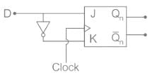
The characteristic equation of a D flip flop is:
Qn+1 = D
It is also known as ‘’Transparent latch” because Qn+1 = D
Application:
From given sequential circuit:
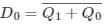 and D1 = Q0
Now,
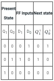
So, counts state (Q1 Q0) follows the sequence:
00 → 01 → 10 → 00 → 01 ….
D-flipflop is a flipflop that produces a delay of exactly one cycle to the CLK.
The characteristic equation of a D flip flop is:
Qn+1 = D
It is also known as ‘’Transparent latch” because Qn+1 = D
Application:
From given sequential circuit:
and D1 = Q0Now,
So, counts state (Q1 Q0) follows the sequence:
00 → 01 → 10 → 00 → 01 ….
Three decade counter would have ____________- a)2 BCD counters
- b)3 BCD counters
- c)4 BCD counters
- d)5 BCD counters
Correct answer is option 'B'. Can you explain this answer?
Three decade counter would have ____________
a)
2 BCD counters
b)
3 BCD counters
c)
4 BCD counters
d)
5 BCD counters
|
|
Sudhir Patel answered |
Three decade counter has 30 states and a BCD counter has 10 states. So, it would require 3 BCD counters. Thus, a three decade counter will count from 0 to 29.
BCD counter is also known as ____________- a)Parallel counter
- b)Decade counter
- c)Synchronous counter
- d)VLSI counter
Correct answer is option 'B'. Can you explain this answer?
BCD counter is also known as ____________
a)
Parallel counter
b)
Decade counter
c)
Synchronous counter
d)
VLSI counter
|
|
Sudhir Patel answered |
BCD counter is also known as decade counter because both have the same number of stages and both count from 0 to 9.
Identify the following sequential component.

- a)Master-slave flip flop
- b)Clocked flip flop
- c)J-K flip flop
- d)R-S flip flop
Correct answer is option 'D'. Can you explain this answer?
Identify the following sequential component.
a)
Master-slave flip flop
b)
Clocked flip flop
c)
J-K flip flop
d)
R-S flip flop
|
|
Sudhir Patel answered |
The given sequential component is of RS Flip Flop.
Here A = R and B = S

The truth table for the circuit is shown:

Here A = R and B = S
The truth table for the circuit is shown:
A sequence detector is designed to detect precisely 3 digital inputs, with overlapping sequences detectable. For the sequence (1,0,1) and input data (1,1,0,1,0,0,1,1,0,1,0,1,1,0), what is the output of this detector?- a)1,1,0,0,0,0,1,1,0,1,0,0
- b)0,1,0,0,0,0,0,1,0,1,0,0
- c)0,1,0,0,0,0,0,1,0,1,1,0
- d)0,1,0,0,0,0,0,0,1,0,0,0
Correct answer is option 'B'. Can you explain this answer?
A sequence detector is designed to detect precisely 3 digital inputs, with overlapping sequences detectable. For the sequence (1,0,1) and input data (1,1,0,1,0,0,1,1,0,1,0,1,1,0), what is the output of this detector?
a)
1,1,0,0,0,0,1,1,0,1,0,0
b)
0,1,0,0,0,0,0,1,0,1,0,0
c)
0,1,0,0,0,0,0,1,0,1,1,0
d)
0,1,0,0,0,0,0,0,1,0,0,0
|
|
Sudhir Patel answered |
A sequence detector is a sequential circuit that outputs 1 when a particular pattern of bits sequentially arrives at its data input.
Given input data = 1,1,0,1,0,0,1,1,0,1,0,1,1,0
Overlapping sequences detectable.
The below table shows the output for each sequence.


The output = 0,1,0,0,0,0,0,1,0,1,0,0
Given input data = 1,1,0,1,0,0,1,1,0,1,0,1,1,0
Overlapping sequences detectable.
The below table shows the output for each sequence.
The output = 0,1,0,0,0,0,0,1,0,1,0,0
A counter circuit is usually constructed of ____________- a)A number of latches connected in cascade form
- b)A number of NAND gates connected in cascade form
- c)A number of flip-flops connected in cascade
- d)A number of NOR gates connected in cascade form
Correct answer is option 'C'. Can you explain this answer?
A counter circuit is usually constructed of ____________
a)
A number of latches connected in cascade form
b)
A number of NAND gates connected in cascade form
c)
A number of flip-flops connected in cascade
d)
A number of NOR gates connected in cascade form
|
|
Sudhir Patel answered |
A counter circuit is usually constructed of a number of flip-flops connected in cascade. Preferably, JK Flip-flops are used to construct counters and registers.
In digital logic, a counter is a device which ____________- a)Counts the number of outputs
- b)Stores the number of times a particular event or process has occurred
- c)Stores the number of times a clock pulse rises and falls
- d)Counts the number of inputs
Correct answer is option 'B'. Can you explain this answer?
In digital logic, a counter is a device which ____________
a)
Counts the number of outputs
b)
Stores the number of times a particular event or process has occurred
c)
Stores the number of times a clock pulse rises and falls
d)
Counts the number of inputs
|
|
Sudhir Patel answered |
In digital logic and computing, a counter is a device which stores (and sometimes displays) the number of times a particular event or process has occurred, often in relationship to a clock signal.
A decimal counter has ______ states.- a)5
- b)10
- c)15
- d)20
Correct answer is option 'B'. Can you explain this answer?
A decimal counter has ______ states.
a)
5
b)
10
c)
15
d)
20
|
|
Sudhir Patel answered |
Decimal counter is also known as 10 stage counter. So, it has 10 states. It is also known as Decade Counter counting from 0 to 9.
The outputs of SR latch are ___________- a)x and y
- b)a and b
- c)s and r
- d)q and q’
Correct answer is option 'D'. Can you explain this answer?
The outputs of SR latch are ___________
a)
x and y
b)
a and b
c)
s and r
d)
q and q’
|
|
Eesha Bhat answered |
SR or Set-Reset latch is the simplest type of bistable multivibrator having two stable states. The inputs of SR latch are s and r while outputs are q and q’. It is clear from the diagram:

Which of the following is correct for a gated D-type flip-flop?- a)The Q output is either SET or RESET as soon as the D input goes HIGH or LOW
- b)The output complement follows the input when enabled
- c)Only one of the inputs can be HIGH at a time
- d)The output toggles if one of the inputs is held HIGH
Correct answer is option 'A'. Can you explain this answer?
Which of the following is correct for a gated D-type flip-flop?
a)
The Q output is either SET or RESET as soon as the D input goes HIGH or LOW
b)
The output complement follows the input when enabled
c)
Only one of the inputs can be HIGH at a time
d)
The output toggles if one of the inputs is held HIGH
|
|
Sudhir Patel answered |
In D flip flop, when the clock is high then the output depends on the input otherwise reminds previous output. In a state of clock high, when D is high the output Q also high, if D is ‘0’ then output is also zero. Like SR flip-flop, the D-flip-flop also have an invalid state at both inputs being 1.
Which of the following can be used for debouncing a switch ?- a)S-R latch
- b)Inverter
- c)Integrator
- d)Pulse generator
Correct answer is option 'A'. Can you explain this answer?
Which of the following can be used for debouncing a switch ?
a)
S-R latch
b)
Inverter
c)
Integrator
d)
Pulse generator
|
|
Eesha Bhat answered |
- Switch bounce or contact bounce or even called chatter is a common problem associated with mechanical switches and relays.
- Switch bouncing is not a major problem when we deal with the power circuits, but it causes problems while we are dealing with the logic and digital circuits.
- Hence, to remove the bouncing from the circuit Switch Debouncing Circuit is used.
- The hardware debouncing technique uses an S-R latch to avoid bounces in the circuit along with the pull-up resistors.
- S-R circuit is the most effective of all debouncing approaches
- The figure below is a simple debouncing circuit that is often used.
SR Latch:
- In an S-R latch, activation of the S input sets the circuit, while activation of the R input resets the circuit.
- If both S and R inputs are activated simultaneously, the circuit will be in an invalid condition.

Application:
- Latches are used to keep the conditions of the bits to encode binary numbers.
- Latches are single-bit storage elements that are widely used in computing as well as data storage.
- Latches are used in the circuits like power gating & clock as a storage device.
The full form of SR is ___________- a)System rated
- b)Set reset
- c)Set ready
- d)Set Rated
Correct answer is option 'B'. Can you explain this answer?
The full form of SR is ___________
a)
System rated
b)
Set reset
c)
Set ready
d)
Set Rated
|
|
Eesha Bhat answered |
The full form of SR is set/reset. It is a type of latch having two stable states.
Ripple counters are also called ____________- a)SSI counters
- b)Asynchronous counters
- c)Synchronous counters
- d)VLSI counters
Correct answer is option 'B'. Can you explain this answer?
Ripple counters are also called ____________
a)
SSI counters
b)
Asynchronous counters
c)
Synchronous counters
d)
VLSI counters
|
|
Sudhir Patel answered |
Ripple counters are also called asynchronous counter. In Asynchronous counters, only the first flip-flop is connected to an external clock while the rest of the flip-flops have their preceding flip-flop output as clock to them.
The first step of the analysis procedure of SR latch is to ___________- a)label inputs
- b)label outputs
- c)label states
- d)label tables
Correct answer is option 'B'. Can you explain this answer?
The first step of the analysis procedure of SR latch is to ___________
a)
label inputs
b)
label outputs
c)
label states
d)
label tables
|
|
Sudhir Patel answered |
All flip flops have at least one output labeled Q (i.e. inverted). This is so because the flip flops have inverting gates inside them, hence in order to have both Q and Q complement available, we have atleast one output labelled.
What is the maximum possible range of bit-count specifically in n-bit binary counter consisting of ‘n’ number of flip-flops?- a)0 to 2n
- b)0 to 2n + 1
- c)0 to 2n – 1
- d)0 to 2n+1/2
Correct answer is option 'C'. Can you explain this answer?
What is the maximum possible range of bit-count specifically in n-bit binary counter consisting of ‘n’ number of flip-flops?
a)
0 to 2n
b)
0 to 2n + 1
c)
0 to 2n – 1
d)
0 to 2n+1/2
|
|
Sudhir Patel answered |
The maximum possible range of bit-count specifically in n-bit binary counter consisting of ‘n’ number of flip-flops is 0 to 2n-1. For say, there is a 2-bit counter, then it will count till 22-1 = 3. Thus, it will count from 0 to 3.
How many types of the counter are there?- a)2
- b)3
- c)4
- d)5
Correct answer is option 'B'. Can you explain this answer?
How many types of the counter are there?
a)
2
b)
3
c)
4
d)
5
|
|
Sudhir Patel answered |
Counters are of 3 types, namely, (i)asynchronous/synchronous, (ii)single and multi-mode & (iii)modulus counter. These further can be subdivided into Ring Counter, Johnson Counter, Cascade Counter, Up/Down Counter and such like.
How many types of sequential circuits are?- a)2
- b)3
- c)4
- d)5
Correct answer is option 'A'. Can you explain this answer?
How many types of sequential circuits are?
a)
2
b)
3
c)
4
d)
5
|
|
Eesha Bhat answered |
There are two type of sequential circuits viz., (i) synchronous or clocked and (ii) asynchronous or unclocked. Synchronous Sequential Circuits are triggered in the presence of a clock signal, whereas, Asynchronous Sequential Circuits function in the absence of a clock signal.
Chapter doubts & questions for Sequential Circuits - 6 Months Preparation for GATE CSE 2025 is part of Computer Science Engineering (CSE) exam preparation. The chapters have been prepared according to the Computer Science Engineering (CSE) exam syllabus. The Chapter doubts & questions, notes, tests & MCQs are made for Computer Science Engineering (CSE) 2025 Exam. Find important definitions, questions, notes, meanings, examples, exercises, MCQs and online tests here.
Chapter doubts & questions of Sequential Circuits - 6 Months Preparation for GATE CSE in English & Hindi are available as part of Computer Science Engineering (CSE) exam.
Download more important topics, notes, lectures and mock test series for Computer Science Engineering (CSE) Exam by signing up for free.
6 Months Preparation for GATE CSE
459 videos|1398 docs|786 tests
|
|
© EduRev
|
Education Revolution
|


|


Signup on EduRev and stay on top of your study goals
10M+ students crushing their study goals daily