


All Exams > Electrical Engineering (EE) > 6 Months Preparation for GATE Electrical > All Questions
All questions of Transistor Biasing & Stabilization for Electrical Engineering (EE) Exam
When the temperature is increased, what happens to the collector current after a feedback is given?- a)it remains same
- b)it increases
- c)it cannot be predicted
- d)it decreases
Correct answer is option 'D'. Can you explain this answer?
When the temperature is increased, what happens to the collector current after a feedback is given?
a)
it remains same
b)
it increases
c)
it cannot be predicted
d)
it decreases
| | Sanvi Kapoor answered |
Before the feedback is applied, when the temperature is increased, the reverse saturation increases. The collector current also increases. When the feedback is applied, the base current increases with decreasing collector current and the thermal runway too.

A silicon power transistor is operated with a heat sink HS-A=1.5°C/W. The transistor rated at 150W (25°C) has HJ-C=0.5°C/W and the mounting insulation has HC-S=0.6°C/W. What maximum power can be dissipated if the ambient temperature is 40°C and (TJ)MAX=200°C?- a)70.6W
- b)61.5W
- c)37.8W
- d)56.9W
Correct answer is option 'B'. Can you explain this answer?
A silicon power transistor is operated with a heat sink HS-A=1.5°C/W. The transistor rated at 150W (25°C) has HJ-C=0.5°C/W and the mounting insulation has HC-S=0.6°C/W. What maximum power can be dissipated if the ambient temperature is 40°C and (TJ)MAX=200°C?
a)
70.6W
b)
61.5W
c)
37.8W
d)
56.9W
 | Sparsh Unni answered |
PD=(TJ-TA)/ HJ-C +HC-S +HS-A
=200-40/0.5+0.6+1.5=61.5W.
=200-40/0.5+0.6+1.5=61.5W.
Thermal stability can be obtained by_________- a)shifting operating point
- b)increasing power supply
- c)heat sink
- d)decreasing current at collector
Correct answer is option 'C'. Can you explain this answer?
Thermal stability can be obtained by_________
a)
shifting operating point
b)
increasing power supply
c)
heat sink
d)
decreasing current at collector
 | Moumita Dasgupta answered |
As power transistors handle large currents, they always heat up during operation. Generally, power transistors are mounted in large metal case to provide a large area from which the heat generated by the device radiates.
When the power dissipation increases in a transistor, the thermal resistance_________- a)increases
- b)cannot be predicted
- c)decreases
- d)remains same
Correct answer is option 'C'. Can you explain this answer?
When the power dissipation increases in a transistor, the thermal resistance_________
a)
increases
b)
cannot be predicted
c)
decreases
d)
remains same
 | Subhankar Ghoshal answered |
The power dissipation is directly proportional to thermal resistance. We have, TJ – TA = θPd in which we can observe θ ∝ 1/Pd. So, a device with low power dissipation has high thermal resistance.
The stability factor for a self biased transistor is_________- a)1 – RTH/RE
- b)1 + RTH/RE
- c) 1 + RE/RTH
- d) 1 – RE/RTH
Correct answer is option 'B'. Can you explain this answer?
The stability factor for a self biased transistor is_________
a)
1 – RTH/RE
b)
1 + RTH/RE
c)
1 + RE/RTH
d)
1 – RE/RTH
 | Aditya Patel answered |
The stability of the circuit is inversely proportional to the stability factor. The emitter resistor is very large when compared to the Thevenin’s resistance. When β is not that large, then S=(1+ β)( RTH+ RE)/ (1+ β)RE+ RTH.
In a silicon transistor, which of the following change significantly to the change in IC?- a)VCE
- b) IB
- c)VBE
- d)IE
Correct answer is option 'C'. Can you explain this answer?
In a silicon transistor, which of the following change significantly to the change in IC?
a)
VCE
b)
IB
c)
VBE
d)
IE
 | Shivani Choudhury answered |
For germanium transistor, changes in ICO with temperature contribute more serious problem than for silicon transistor. On the other hand, in a silicon transistor, the changes of VBE with temperature possesses significantly to the changes in IC.
Compensation techniques refer to the use of_________- a)diodes
- b)capacitors
- c)resistors
- d)transformers
Correct answer is option 'A'. Can you explain this answer?
Compensation techniques refer to the use of_________
a)
diodes
b)
capacitors
c)
resistors
d)
transformers
 | Moumita Chopra answered |
Compensation techniques refer to the use of temperature sensitive devices such as thermistors, diodes, transistors, sensistors etc to compensate variation in currents. Sometimes for excellent bias and thermal stabilization, both stabilization and compensation techniques are used.
Thermal stability is dependent on thermal runaway which is_________- a)an uncontrolled positive feedback
- b)a controlled positive feedback
- c)an uncontrolled negative feedback
- d)a controlled negative feedback
Correct answer is option 'A'. Can you explain this answer?
Thermal stability is dependent on thermal runaway which is_________
a)
an uncontrolled positive feedback
b)
a controlled positive feedback
c)
an uncontrolled negative feedback
d)
a controlled negative feedback
 | Devanshi Iyer answered |
Thermal runaway is a self destruction process in which an increase in temperature creates such a condition which in turn increases the temperature again. This uncontrolled rise in temperature causes the component to get damaged.
The negative feedback does good for DC signal by_________- a)decreasing the gain
- b)increasing the gain
- c)stabilising the operating point
- d)increasing the stability factor
Correct answer is option 'C'. Can you explain this answer?
The negative feedback does good for DC signal by_________
a)
decreasing the gain
b)
increasing the gain
c)
stabilising the operating point
d)
increasing the stability factor
| | Ishan Chawla answered |
Stabilizing the operating point is the correct answer because negative feedback in a DC signal helps to maintain a stable and desired operating point in a circuit. Let's explore this in detail:
Negative feedback is a technique used in electronic circuits to improve the performance and stability of the system. It involves taking a portion of the output signal and feeding it back to the input with an opposite polarity. In the case of DC signals, the feedback is applied to maintain the desired operating point or biasing conditions.
Stabilizing the Operating Point:
The operating point of a circuit is the DC voltage or current level at which the circuit is designed to operate. It determines the biasing conditions of active devices such as transistors and sets the desired quiescent point for proper circuit operation.
Negative feedback helps to stabilize the operating point by continuously adjusting the circuit conditions in response to any variations or disturbances. When there is a change in the operating conditions, the feedback mechanism senses it and adjusts the circuit parameters to bring it back to the desired operating point.
This stabilization is achieved through the following mechanisms:
1. Compensation: Negative feedback compensates for any changes in the circuit components, temperature, or other environmental factors. It automatically adjusts the circuit parameters to maintain the desired operating conditions.
2. Error Correction: Any deviation from the desired operating point is considered an error. Negative feedback senses this error and applies corrective measures to minimize it. By continuously monitoring the output and comparing it with the desired value, the feedback mechanism makes necessary adjustments to bring the error to zero.
3. Linearity Improvement: Negative feedback helps to improve the linearity of the circuit. It reduces distortions and nonlinearities by counteracting the nonlinear effects of active devices. This improves the overall performance and stability of the circuit.
4. Noise Reduction: Negative feedback also helps to reduce noise in the circuit. By attenuating the noise components present in the output, it minimizes their impact on the desired DC signal. This results in a cleaner and more stable output.
In summary, negative feedback in a DC signal stabilizes the operating point of a circuit by compensating for changes, correcting errors, improving linearity, and reducing noise. It ensures that the circuit operates in a stable and desired manner, providing reliable and accurate results.
Thermal runaway is_________- a)an uncontrolled positive feedback
- b)a controlled positive feedback
- c)an uncontrolled negative feedback
- d)a controlled negative feedback
Correct answer is option 'A'. Can you explain this answer?
Thermal runaway is_________
a)
an uncontrolled positive feedback
b)
a controlled positive feedback
c)
an uncontrolled negative feedback
d)
a controlled negative feedback
| | Sandeep Saha answered |
Thermal runaway is an uncontrolled positive feedback.
Explanation:
Thermal runaway is a phenomenon that occurs when the temperature of a system increases rapidly due to a positive feedback loop. In this feedback loop, an increase in temperature leads to an increase in some parameter, which in turn further increases the temperature, creating a self-reinforcing cycle. This positive feedback loop is uncontrolled and can lead to catastrophic consequences if not managed properly.
Positive Feedback:
Positive feedback occurs when the output of a system amplifies the input, leading to an increase in the initial disturbance. In the case of thermal runaway, the increase in temperature causes a parameter (such as resistance or current) to increase, which further increases the temperature. This positive feedback loop continues until the system reaches its limit or fails.
Uncontrolled Feedback:
Thermal runaway is considered to be uncontrolled because it occurs without any external intervention or regulation. Once the positive feedback loop is initiated, it continues to amplify itself without any external control. This can lead to a rapid and uncontrollable rise in temperature, which can cause damage to the system or even result in a catastrophic failure.
Consequences of Thermal Runaway:
Thermal runaway can have severe consequences, especially in electrical systems. The rapid increase in temperature can damage components, degrade insulation materials, and even lead to fires or explosions. It is particularly dangerous in high-power systems where the dissipated heat is significant.
Prevention and Control:
To prevent thermal runaway, various measures can be taken. These include the use of thermal protection devices such as thermal fuses or circuit breakers, adequate cooling systems, temperature monitoring, and control algorithms. These measures help in detecting and controlling the temperature rise, preventing thermal runaway and ensuring the safe operation of the system.
A silicon NPN transistor is used and it has a large value of β. Find the required value of R2when IC=1mA.
- a)10kΩ
- b)20kΩ
- c)30kΩ
- d)40kΩ
Correct answer is option 'D'. Can you explain this answer?
A silicon NPN transistor is used and it has a large value of β. Find the required value of R2when IC=1mA.
a)
10kΩ
b)
20kΩ
c)
30kΩ
d)
40kΩ
| | Yash Patel answered |
For silicon, VBE=0.8V, VCE=0.2V. IC=VTH-VBE/RE. By pitting the values, we have VTH=1.3V. R2 can be found from, VCCR2/R1+R2. We get R2=40KΩ.
In the circuit, transistor has β =60, VBE=0.7V. Find the collector to emitter voltage drop VCE.
- a)5V
- b)3V
- c)8V
- d)6V
Correct answer is option 'D'. Can you explain this answer?
In the circuit, transistor has β =60, VBE=0.7V. Find the collector to emitter voltage drop VCE.
a)
5V
b)
3V
c)
8V
d)
6V
| | Sanskriti Desai answered |
We know, IC=(VCC-VBE)/RB
By putting the values, we have IC=5.9mA. IE=IC/α. So, IE=5.99mA.
VCE= VCC-RC(IC+IB). We have VCE=6V.
By putting the values, we have IC=5.9mA. IE=IC/α. So, IE=5.99mA.
VCE= VCC-RC(IC+IB). We have VCE=6V.
Which of the following biasing techniques are prone to thermal runaway?- a)self bias
- b)collector to base bias
- c)fixed bias
- d)the biasing technique is identified by temperature effect
Correct answer is option 'C'. Can you explain this answer?
Which of the following biasing techniques are prone to thermal runaway?
a)
self bias
b)
collector to base bias
c)
fixed bias
d)
the biasing technique is identified by temperature effect
 | Bhavya Rane answered |
The collector current of a fixed bias transistor is IC= β(VCC-VBE)/RB. When the temperature is increased, the reverse saturation increases. The collector current also increases. This in turn increases the current again which leads to damage of transistor.
The negative sign in the formula of amplification factor indicates_________- a)that IE flows into transistor while IC flows out it
- b)that IC flows into transistor while IE flows out it
- c) that IB flows into transistor while IC flows out it
- d) that IC flows into transistor while IB flows out it
Correct answer is option 'A'. Can you explain this answer?
The negative sign in the formula of amplification factor indicates_________
a)
that IE flows into transistor while IC flows out it
b)
that IC flows into transistor while IE flows out it
c)
that IB flows into transistor while IC flows out it
d)
that IC flows into transistor while IB flows out it
 | Bijoy Chauhan answered |
When no signal is applied, the ratio of collector current to emitter current is called dc alpha, αdc of a transistor. αdc=-IC/IE. It is the measure of the quality of a transistor. Higher is the value of α, better is the transistor in the sense that collector current approaches the emitter current.
For a given transistor, the thermal resistance is 8°C/W and for the ambient temperature TAis 27°C. If the transistor dissipates 3W of power, calculate the junction temperature (TJ).- a)51°C
- b)27°C
- c)67°C
- d)77°C
Correct answer is option 'A'. Can you explain this answer?
For a given transistor, the thermal resistance is 8°C/W and for the ambient temperature TAis 27°C. If the transistor dissipates 3W of power, calculate the junction temperature (TJ).
a)
51°C
b)
27°C
c)
67°C
d)
77°C
| | Arindam Sengupta answered |
We know, TJ-TA=HPD
TJ=TA+HPD=27+8*3=51°C.
TJ=TA+HPD=27+8*3=51°C.
The compensation techniques are used to_________- a)increase stability
- b)increase the voltage gain
- c)improve negative feedback
- d)decrease voltage gain
Correct answer is option 'B'. Can you explain this answer?
The compensation techniques are used to_________
a)
increase stability
b)
increase the voltage gain
c)
improve negative feedback
d)
decrease voltage gain
 | Lekshmi Kaur answered |
Usually, the negative feedback is used to produce a stable operating point. But it reduces the voltage gain of the circuit. This sometimes is intolerable and should be avoided in some applications. So, the biasing techniques are used.
The demerit of a collector to base bias is_________- a)its need of high resistance values
- b)its dependence on β
- c)its independence on β
- d)the positive feedback produced by the base resistor
Correct answer is option 'A'. Can you explain this answer?
The demerit of a collector to base bias is_________
a)
its need of high resistance values
b)
its dependence on β
c)
its independence on β
d)
the positive feedback produced by the base resistor
 | Sameer Verma answered |
When the stability factor S=1, the collector resistor value should be very large when compared to the base resistor. So, when RC is large we need to provide large power supply which increases the cost. At the same time, as the base resistor is small we need to provide small power supply.
The condition to be satisfied to prevent thermal runaway?- a)∂PC/∂TJ > 1/Q
- b)∂PC/∂TJ < 1/Q
- c)∂PC/∂TJ > 1
- d)none
Correct answer is option 'B'. Can you explain this answer?
The condition to be satisfied to prevent thermal runaway?
a)
∂PC/∂TJ > 1/Q
b)
∂PC/∂TJ < 1/Q
c)
∂PC/∂TJ > 1
d)
none
| | Lekshmi Kaur answered |
PC is the power dissipated at the collector junction. TJ is junction temperature which varies. The difference between these temperatures is directly proportional to the power dissipation. Here, Q is called as thermal resistance which is proportionality constant.
The total thermal resistance of a power transistor and heat sink is 20°C/W. The ambient temperature is 25°C and (TJ)MAX=200°C. If VCE=4V, find the maximum collector current that the transistor can carry without destruction. What will be the allowed value of collector current if ambient temperature rises to 75°C?- a)3.67A
- b)7.56A
- c)2.19A
- d)1.56A
Correct answer is option 'D'. Can you explain this answer?
The total thermal resistance of a power transistor and heat sink is 20°C/W. The ambient temperature is 25°C and (TJ)MAX=200°C. If VCE=4V, find the maximum collector current that the transistor can carry without destruction. What will be the allowed value of collector current if ambient temperature rises to 75°C?
a)
3.67A
b)
7.56A
c)
2.19A
d)
1.56A
 | Subhankar Malik answered |
PD =(TJ-TA)/ H
=200-75/20=6.25W.
Now, IC = 6.25/4=1.56A.
=200-75/20=6.25W.
Now, IC = 6.25/4=1.56A.
When the collector current is increased in a transistor_________- a)the reverse current is increased
- b)the temperature is increased
- c)collisions of electrons decrease
- d)the emitter does not emit electrons
Correct answer is option 'B'. Can you explain this answer?
When the collector current is increased in a transistor_________
a)
the reverse current is increased
b)
the temperature is increased
c)
collisions of electrons decrease
d)
the emitter does not emit electrons
| | Subhankar Ghoshal answered |
As the collector current is increased, the emitter releases more number of electrons. This causes more collisions of electrons at collector. This happens in a cycle and produces such a condition in which temperature is further more increased.
The expression for IC in the compensation for instability due to ICO variation_________- a)βI+βIO+βICO
- b)βI+βIO
- c)βIO+βICO
- d)βI+βICO
Correct answer is option 'A'. Can you explain this answer?
The expression for IC in the compensation for instability due to ICO variation_________
a)
βI+βIO+βICO
b)
βI+βIO
c)
βIO+βICO
d)
βI+βICO
 | Ankit Mukherjee answered |
In this method, diode is used for the compensation in variation of ICO. The diode used is of the same material and type as that of transistor. Hence, the reverse saturation current IO of the diode will increase with temperature at the same rate as the transistor collector saturation current ICO.
Which of the following has a negative temperature coefficient of resistance?- a)sensistor
- b)diode
- c)thermistor
- d)capacitor
Correct answer is option 'C'. Can you explain this answer?
Which of the following has a negative temperature coefficient of resistance?
a)
sensistor
b)
diode
c)
thermistor
d)
capacitor
| | Sarita Yadav answered |
The thermistor has a negative temperature coefficient of resistance. It means, its resistance decreases exponentially with increasing T. The thermistor RT is used to minimize the increase in collector current.
The output resistance of CB transistor is given by _________- a) ∆VCB/∆IC
- b) ∆VBE/∆IB
- c)∆VBE/∆IC
- d)∆VEB/∆IE
Correct answer is option 'A'. Can you explain this answer?
The output resistance of CB transistor is given by _________
a)
∆VCB/∆IC
b)
∆VBE/∆IB
c)
∆VBE/∆IC
d)
∆VEB/∆IE
 | Avik Chaudhary answered |
The ratio of change in collector base voltage (∆VCB) to resulting change in collector current (∆IC) at constant emitter current (IE) is defined as output resistance. This is denoted by ro.

The collector current (IC) that is obtained in a self biased transistor is_________- a)(VTH – VB)/RE
- b)(VTH + VBE)/RE
- c)(VTH + VB)/RE
- d)none
Correct answer is option 'A'. Can you explain this answer?
The collector current (IC) that is obtained in a self biased transistor is_________
a)
(VTH – VB)/RE
b)
(VTH + VBE)/RE
c)
(VTH + VB)/RE
d)
none
 | Diya Chopra answered |
The collector current is analysed by the DC analysis of a transistor. It involves the DC equivalent circuit of a transistor. The base current is first found and the collector current is obtained from the relation, IC=IBβ.
The thermal runway is avoided in a self bias because_________- a)of its independence of β
- b)of the positive feedback produced by the emitter resistor
- c)of the negative feedback produced by the emitter resistor
- d)of its dependence of β
Correct answer is option 'C'. Can you explain this answer?
The thermal runway is avoided in a self bias because_________
a)
of its independence of β
b)
of the positive feedback produced by the emitter resistor
c)
of the negative feedback produced by the emitter resistor
d)
of its dependence of β
 | Arya Kaur answered |
The self destruction of a transistor due to increase temperature is called thermal run away. It is avoided by the negative feedback produced by the emitter resistor in a self bias. The IC which is responsible for the damage is reduced by decreased output signal.
When the temperature is increased, what happens to the collector current after a feedback is given?- a)it remains same
- b)it increases
- c)it cannot be predicted
- d)it decreases
Correct answer is option 'D'. Can you explain this answer?
When the temperature is increased, what happens to the collector current after a feedback is given?
a)
it remains same
b)
it increases
c)
it cannot be predicted
d)
it decreases
 | Milan Saha answered |
Before the feedback is applied, when the temperature is increased, the reverse saturation increases. The collector current also increases. When the feedback is applied, the drop across the emitter resistor increases with decreasing collector current and the thermal runway too.
The collector to emitter voltage (VCE) is obtained by_________- a)VCC – RC(IC-IB)
- b)VCC – RC(IC+IB)
- c)VCC + RC(IC+IB)
- d)VCC + RC(IC-IB)
Correct answer is option 'B'. Can you explain this answer?
The collector to emitter voltage (VCE) is obtained by_________
a)
VCC – RC(IC-IB)
b)
VCC – RC(IC+IB)
c)
VCC + RC(IC+IB)
d)
VCC + RC(IC-IB)
 | Saptarshi Nair answered |
The collector to emitter voltage is obtained in order to find the operating point of a transistor. It is taken when there is no signal applied to the transistor. The point thus obtained lies in the cut off region when the transistor is used as a switch.
In the circuit, the transistor has a large β value (VBE=0.7V). Find the current through RC.
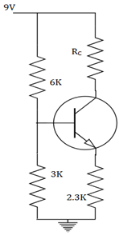
- a)0.5mA
- b)2mA
- c)1mA
- d)1.6mA
Correct answer is option 'C'. Can you explain this answer?
In the circuit, the transistor has a large β value (VBE=0.7V). Find the current through RC.
a)
0.5mA
b)
2mA
c)
1mA
d)
1.6mA
 | Mahesh Yadav answered |
We know, IC=VTH-VBE/RE
=9*3/9=3V. IC=3-0.7/2.3=1mA.
=9*3/9=3V. IC=3-0.7/2.3=1mA.
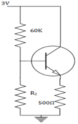
What is the Thevenin’s voltage (VTH) in a self bias shown below?
- a)VCCR2/R1+R2
- b)VCCR1/R1+R2
- c)VCCR2/R1-R2
- d)none
Correct answer is option 'A'. Can you explain this answer?
What is the Thevenin’s voltage (VTH) in a self bias shown below?
a)
VCCR2/R1+R2
b)
VCCR1/R1+R2
c)
VCCR2/R1-R2
d)
none
 | Arjun Unni answered |
The base current cannot be obtained directly from the KVL or KCL applications. The VCC and VBE cannot come under a single equation. So, the circuit is changed with a Thevenin’s voltage (VTH) and Thevenin’s resistance.
When the temperature is increased, what happens to the collector current after a feedback is given?- a)it remains same
- b)it increases
- c)it cannot be predicted
- d)it decreases
Correct answer is option 'D'. Can you explain this answer?
When the temperature is increased, what happens to the collector current after a feedback is given?
a)
it remains same
b)
it increases
c)
it cannot be predicted
d)
it decreases
 | Neha Basak answered |
Before the feedback is applied, when the temperature is increased, the reverse saturation increases. The collector current also increases. When the feedback is applied, the base current increases with decreasing collector current and the thermal runway too.
What is the DC characteristic used to prove that the transistor is indeed biased in saturation mode?- a)IC = βIB
- b) IC > βIB
- c)IC >> βIB
- d)IC < βIB
Correct answer is option 'D'. Can you explain this answer?
What is the DC characteristic used to prove that the transistor is indeed biased in saturation mode?
a)
IC = βIB
b)
IC > βIB
c)
IC >> βIB
d)
IC < βIB
| | Jaya Yadav answered |
When in a transistor is driven into saturation, we use VCE(SAT) as another linear parameter. In, addition when a transistor is biased in saturation mode, we have IC < βIB. This characteristic used to prove that the transistor is indeed biased in saturation mode.
What is the compensation element used for variation in VBE and ICO?- a)diodes
- b)capacitors
- c)resistors
- d)transformers
Correct answer is option 'A'. Can you explain this answer?
What is the compensation element used for variation in VBE and ICO?
a)
diodes
b)
capacitors
c)
resistors
d)
transformers
| | Mahesh Yadav answered |
A diode is used as the compensation element used variation in VBE and ICO. The diode used is of the same material and type as that of transistor. Hence, the voltage across the diode has same temperature coefficient as VBE of the transistor.
The thermal runway is avoided in a collector to base bias because_________- a)of its independence of β
- b)of the positive feedback produced by the base resistor
- c)of the negative feedback produced by the base resistor
- d)of its dependence of β
Correct answer is option 'C'. Can you explain this answer?
The thermal runway is avoided in a collector to base bias because_________
a)
of its independence of β
b)
of the positive feedback produced by the base resistor
c)
of the negative feedback produced by the base resistor
d)
of its dependence of β
 | Kritika Shah answered |
The self destruction of a transistor due to increase temperature is called thermal run away. It is avoided by the negative feedback produced by the base resistor in a collector to base bias. The IC which is responsible for the damage is reduced by decreased output signal.
Which of the following are true?- a) TJ – TA = θPd
- b) TJ – TA = θ/Pd
- c)TJ – TA = θ+Pd
- d)TJ – TA = θ-Pd
Correct answer is option 'A'. Can you explain this answer?
Which of the following are true?
a)
TJ – TA = θPd
b)
TJ – TA = θ/Pd
c)
TJ – TA = θ+Pd
d)
TJ – TA = θ-Pd
 | Anushka Bose answered |
The TJ is called as junction temperature which varies and TA is called as the ambient temperature which is fixed. The difference between these temperatures is directly proportional to the power dissipation. Here, θ is called as thermal resistance which is proportionality constant.
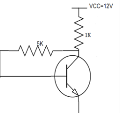
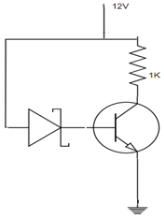
In the circuit shown below, β =100 and VBE=0.7V. The Zener diode has a breakdown voltage of 6V. Find the operating point.
- a)(6.7V, 5.3mA)
- b)(5.7V, 5.3mA)
- c)(6.7V, 5mA)
- d)(6V, 5mA)
Correct answer is option 'A'. Can you explain this answer?
In the circuit shown below, β =100 and VBE=0.7V. The Zener diode has a breakdown voltage of 6V. Find the operating point.
a)
(6.7V, 5.3mA)
b)
(5.7V, 5.3mA)
c)
(6.7V, 5mA)
d)
(6V, 5mA)
| | Neha Nambiar answered |
We know, by KVL -12+(IC+IB)1K+6+VBE=0
We have IE=5.3. IC= αIE=5.24mA. From another loop, -12+IEIK+VBE=0
We have, VCE=12-5.3m*1000=6.7V. Hence the Q point is (6.7V, 5.3mA).
We have IE=5.3. IC= αIE=5.24mA. From another loop, -12+IEIK+VBE=0
We have, VCE=12-5.3m*1000=6.7V. Hence the Q point is (6.7V, 5.3mA).
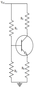
What is the Thevenin’s resistance (RTH) in a self bias shown below?
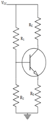
- a)R1R2/R1+R2
- b)R2/R1+R2
- c)R1R2/R1-R2
- d)R1/R1-R2
Correct answer is option 'A'. Can you explain this answer?
What is the Thevenin’s resistance (RTH) in a self bias shown below?
a)
R1R2/R1+R2
b)
R2/R1+R2
c)
R1R2/R1-R2
d)
R1/R1-R2
| | Jaya Yadav answered |
The base current cannot be obtained directly from the KVL or KCL applications. A potential divider network is formed by R1 and R2.The VCC and VBE cannot come under a single equation. So, the circuit is changed with a Thevenin’s resistance.
The collector current (IC) that is obtained in a collector to base biased transistor is_________- a)(VCC-VBE)/RB
- b) (VCC+VBE)/RB
- c)(VCE-VBE)/RB
- d)(VCE+VBE)/RB
Correct answer is option 'A'. Can you explain this answer?
The collector current (IC) that is obtained in a collector to base biased transistor is_________
a)
(VCC-VBE)/RB
b)
(VCC+VBE)/RB
c)
(VCE-VBE)/RB
d)
(VCE+VBE)/RB
| | Mahesh Yadav answered |
The collector current is analysed by the DC analysis of a transistor. It involves the DC equivalent circuit of a transistor. The base current is first found and the collector current is obtained from the relation, IC=IBβ.
When the β value is large for a given transistor, the IC and VCE values are given by_________- a)(VCC-VBE)/RB, VCC-RCIC
- b)(VCC+VBE)/RB, VCC-RC(IC+IB)
- c)(VCC+VBE)/RB, VCC+RC(IC+IB)
- d)(VCC+VBE)/RB, VCC+RC(IC-IB)
Correct answer is option 'A'. Can you explain this answer?
When the β value is large for a given transistor, the IC and VCE values are given by_________
a)
(VCC-VBE)/RB, VCC-RCIC
b)
(VCC+VBE)/RB, VCC-RC(IC+IB)
c)
(VCC+VBE)/RB, VCC+RC(IC+IB)
d)
(VCC+VBE)/RB, VCC+RC(IC-IB)
| | Mahesh Yadav answered |
The base current IB is zero when β value is large. So, the VCE changes to VCC-RCIC. The collector current IC is changed to (VCC-VBE)/RB from β(VCC-VBE)/(1+ β)RE+ RB.
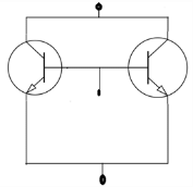
Discrete transistors T1 and T2 having maximum collector current rating of 0.75A are connected in parallel as shown in the figure. This combination is treated as a single transistor to carry a single current of 1A, when biased with a self bias circuit. When the circuit is switched ON, T1 had draws 0.55A and T2 draws 0.45A. If the supply is kept ON continuously, it is very likely that_________
- a)both T1 and T2 get damaged
- b) both T1 and T2 will be safe
- c)only T1 gets damaged
- d)only T2 gets damaged
Correct answer is option 'C'. Can you explain this answer?
Discrete transistors T1 and T2 having maximum collector current rating of 0.75A are connected in parallel as shown in the figure. This combination is treated as a single transistor to carry a single current of 1A, when biased with a self bias circuit. When the circuit is switched ON, T1 had draws 0.55A and T2 draws 0.45A. If the supply is kept ON continuously, it is very likely that_________
a)
both T1 and T2 get damaged
b)
both T1 and T2 will be safe
c)
only T1 gets damaged
d)
only T2 gets damaged
 | Manisha Chavan answered |
The T1 transistor is having more power dissipation as it is drawing 0.55A. When power dissipation increases, the temperature increases and this leads to the ultimate further increase in the current drawn by T1. The current drawn by T2 will be reduced as the sum of currents drawn by T1 and T2 should be constant.
The value of αac for all practical purposes, for commercial transistors range from_________- a)0.5 to 0.6
- b)0.7 to 0.77
- c)0.8 to 0.88
- d)0.9 to 0.99
Correct answer is option 'D'. Can you explain this answer?
The value of αac for all practical purposes, for commercial transistors range from_________
a)
0.5 to 0.6
b)
0.7 to 0.77
c)
0.8 to 0.88
d)
0.9 to 0.99
 | Bhaskar Joshi answered |
For all practical purposes, αac=αdc=α and practical values in commercial transistors range from 0.9-0.99. It is the measure of the quality of a transistor. Higher is the value of α, better is the transistor in the sense that collector current approaches the emitter current.
Which of the following is true?- a)HC-A = HJ-C – HJ-A
- b) HC-A = HJ-C + HJ-A
- c)HJ-A = HJ-C – HC-A
- d)HJ-A = HJ-C + HC-A
Correct answer is option 'D'. Can you explain this answer?
Which of the following is true?
a)
HC-A = HJ-C – HJ-A
b)
HC-A = HJ-C + HJ-A
c)
HJ-A = HJ-C – HC-A
d)
HJ-A = HJ-C + HC-A
 | Ishaan Kulkarni answered |
HJ-C is thermal resistance between junction and case and HC-A is thermal resistance between case and ambient. The circuit designer has no control over HJ-C. So, a proper approach to dissipate heat from case to ambient is through heat sink.
Chapter doubts & questions for Transistor Biasing & Stabilization - 6 Months Preparation for GATE Electrical 2026 is part of Electrical Engineering (EE) exam preparation. The chapters have been prepared according to the Electrical Engineering (EE) exam syllabus. The Chapter doubts & questions, notes, tests & MCQs are made for Electrical Engineering (EE) 2026 Exam. Find important definitions, questions, notes, meanings, examples, exercises, MCQs and online tests here.
Chapter doubts & questions of Transistor Biasing & Stabilization - 6 Months Preparation for GATE Electrical in English & Hindi are available as part of Electrical Engineering (EE) exam. Download more important topics, notes, lectures and mock test series for Electrical Engineering (EE) Exam by signing up for free.
6 Months Preparation for GATE Electrical675 videos|1390 docs|885 tests |