


All Exams >
Mechanical Engineering >
SSC JE Mechanical Mock Test Series 2026 >
All Questions
All questions of Manufacturing Engineering for Mechanical Engineering Exam
Which of the following can be used to scribe lines parallel to the edges of a part- a)Vernier calipers
- b)Screw gauge
- c)Divider
- d)Hermaphrodite
Correct answer is option 'D'. Can you explain this answer?
Which of the following can be used to scribe lines parallel to the edges of a part
a)
Vernier calipers
b)
Screw gauge
c)
Divider
d)
Hermaphrodite
|
|
Sarita Yadav answered |
The hermaphrodite caliper is a tool used to layout lines that are parallel with the edges of the work piece. It can also be used to locate the center of cylindrical shaped workplaces.


Draft is provided in pattern so that:- a)It can be easily withdrawn from mould cavity
- b)Sand can be filled easily
- c)Compression can be done effectively
- d)Casting can be solidifying easily
Correct answer is option 'A'. Can you explain this answer?
Draft is provided in pattern so that:
a)
It can be easily withdrawn from mould cavity
b)
Sand can be filled easily
c)
Compression can be done effectively
d)
Casting can be solidifying easily

|
Raghav Mukherjee answered |
The Purpose of Draft in Pattern Making
Introduction
Pattern making is a crucial step in the casting process. It involves the creation of a replica of the desired final product, called a pattern, which is used to shape the mold cavity. The pattern is typically made from wood, metal, or plastic and is designed with specific features to facilitate the casting process. One of these features is the inclusion of draft.
What is Draft?
Draft, also known as taper, is a slight inclination or angle provided on the vertical surfaces of a pattern. It is measured in degrees and is necessary to ensure the smooth extraction of the pattern from the mold cavity. Draft is typically applied to all vertical surfaces of the pattern, including the core prints, side walls, and bosses.
Reasons for Providing Draft in Pattern Making
1. Easy Withdrawal from Mold Cavity
The primary reason for providing draft in pattern making is to facilitate the easy withdrawal of the pattern from the mold cavity. The inclusion of draft allows the pattern to be smoothly lifted out of the mold without damaging the mold or the pattern itself. Without draft, the pattern would get stuck in the mold, making it difficult to remove and potentially causing damage to both the pattern and the mold.
2. Sand Filling
While draft primarily aids in the withdrawal of the pattern, it also helps in the sand filling process. The inclusion of draft allows for easier and smoother sand filling around the pattern. The draft angle helps prevent the sand from sticking to the pattern, ensuring that it can be easily removed once the mold is formed.
3. Effective Compression
Draft also plays a role in effective compression of the molding sand. When the pattern is pressed into the sand, the draft angle allows for better compaction of the sand particles. This results in a more stable mold cavity with improved dimensional accuracy and surface finish.
4. Easy Solidification of Casting
Additionally, draft contributes to the easy solidification of the casting material. The inclination of the pattern's vertical surfaces allows for uniform cooling and shrinkage of the molten metal during solidification. This helps prevent the formation of defects, such as shrinkage cavities and cracks, in the final casting.
Conclusion
In conclusion, the inclusion of draft in pattern making is essential for several reasons. It facilitates the easy withdrawal of the pattern from the mold cavity, enables smooth sand filling, ensures effective compression of the molding sand, and promotes easy solidification of the casting material. All these factors contribute to the production of high-quality castings with accurate dimensions and improved surface finish.
The main objective of ‘shot peening’ is to improve which property of metal parts- a)Surface finish
- b)Ductility
- c)Fatigue strength
- d)None of the above
Correct answer is option 'C'. Can you explain this answer?
The main objective of ‘shot peening’ is to improve which property of metal parts
a)
Surface finish
b)
Ductility
c)
Fatigue strength
d)
None of the above

|
Navya Saha answered |
Explanation:
Surface Finish:
Shot peening is a process used to improve the fatigue strength of metal parts, not the surface finish. Although shot peening can also have some effects on the surface finish of the parts, its primary objective is to enhance other properties.
Ductility:
Shot peening does not primarily aim to improve the ductility of metal parts. Ductility is the ability of a material to deform plastically before fracturing, and shot peening does not directly influence this property.
Fatigue Strength:
The main objective of shot peening is to improve the fatigue strength of metal parts. Fatigue strength is the ability of a material to resist fatigue failure when subjected to cyclic loading. Shot peening induces compressive residual stresses on the surface of the part, which helps to increase its fatigue strength by preventing crack initiation and propagation.
Conclusion:
In conclusion, the correct answer is option C - fatigue strength. Shot peening is a surface treatment process that is specifically designed to enhance the fatigue strength of metal parts by introducing compressive residual stresses on their surfaces.
The crystal structure of Copper is- a)Body - centred cubic
- b)Face - centred cubic
- c)Close - packed hexagonal
- d)Body - centred tetragonal
Correct answer is option 'B'. Can you explain this answer?
The crystal structure of Copper is
a)
Body - centred cubic
b)
Face - centred cubic
c)
Close - packed hexagonal
d)
Body - centred tetragonal
|
|
Hiral Jain answered |
Crystal structure of Material
FCC: - Ni, Cu, Ag, Pt, Au, Pb, Al, Austenite or Ƴ-iron
BCC: - V, Mo, Ta, W, Ferrite or α-iron, δ-ferrite or δ-iron
HCP: - Mg, Zn,
Cobalt: - HCP < 420°C, FCC > 420°C
Chromium:- HCP < 20°C, BCC > 20°C
Glass: - Amorphous
Gears are manufactured in mass production by:- a)Milling
- b)Shaping
- c)Hobbing
- d)Forming
Correct answer is option 'C'. Can you explain this answer?
Gears are manufactured in mass production by:
a)
Milling
b)
Shaping
c)
Hobbing
d)
Forming
|
|
Simran Dasgupta answered |
Gear Hobbing is a continuous generating process in which the tooth flanks of the constantly moving work piece are formed by equally spaced cutting edges of the hob. The main advantage of this process is its versatility to produce a variety of gears including Spur, Helical, Worm Wheels, Serrations, Splines, etc. The main advantage of the method is the higher productivity rate of the gears.
Gear Milling is one of the initial and best known and metal removal process for making gears. This method requires the usage of a milling machine. This method is right now used only for the manufacture of gears requiring very less dimensional accuracy.
Gear shaping is a generating process. The cutter used is virtually a gear provided with cutting edges. The tool is rotated at the required velocity ratio relative to the gear to be manufactured and any one manufactured gear tooth space is formed by one complete cutter tooth. This method can be used to produce cluster gears, internal gears, racks, etc with ease, which may not have the possibility to be manufactured in gear hobbing.
Gear forming: In gear form cutting, the cutting edge of the cutting tool has a shape identical with the shape of the space between the gear teeth. Two machining operations, milling and broaching can be employed to form cut gear teeth.
Cemented carbide tools are usually provided with:- a)Positive back rake angle
- b)Negative back rake angle
- c)Zero rake angle
- d)None of the above
Correct answer is option 'B'. Can you explain this answer?
Cemented carbide tools are usually provided with:
a)
Positive back rake angle
b)
Negative back rake angle
c)
Zero rake angle
d)
None of the above
|
|
Lakshmi Datta answered |
Positive rake – helps reduce cutting force and thus cutting power requirement.
Negative rake – to increase edge-strength and life of the tool
Zero rake – to simplify design and manufacture of the form tools
Negative back rake angle is preferable for carbide tool. Carbide tools are very brittle in nature, so deformation occurs if we provide positive back rake angle.
Positive back rake angle is used for machining low tensile strength and non-ferrous materials. Negative back rake angles are used for machining high tensile strength material, heavy feed and interrupted cuts.
Which of the following surface hardening processes needs not quenching?- a)Induction hardening
- b)Flame hardening
- c)Nitriding
- d)Case carburising
Correct answer is option 'C'. Can you explain this answer?
Which of the following surface hardening processes needs not quenching?
a)
Induction hardening
b)
Flame hardening
c)
Nitriding
d)
Case carburising
|
|
Rashi Shah answered |
Flame or induction hardening are processes in which the surface of the steel is heated very rapidly to high temperatures (by direct application of an oxy-gas flame, or by induction heating) then cooled rapidly, generally using water; this creates a "case" of martensite on the surface.
Carburizing is a process used to case-harden steel with a carbon content between 0.1 and 0.3 wt% C. In this process steel is introduced to a carbon rich environment and elevated temperatures for a certain amount of time, and then quenched so that the carbon is locked in the structure.
Nitriding heats the steel part to 482-621°C (900-1,150°F) in an atmosphere of ammonia gas and dissociated ammonia. The time the part spends in this environment dictates the depth of the case. No quenching is done after nitriding.
In a shaper, material is removed during:- a)forward stroke
- b)neither the forward nor the return stroke
- c)both the forward and return strokes
- d)return stroke
Correct answer is option 'A'. Can you explain this answer?
In a shaper, material is removed during:
a)
forward stroke
b)
neither the forward nor the return stroke
c)
both the forward and return strokes
d)
return stroke
|
|
Yash Das answered |
Shaper and Material Removal
A shaper is a machine tool used for shaping or surfacing metal and other materials. It is used to produce flat or curved surfaces with the help of a single-point cutting tool. The tool is mounted on the ram and reciprocates over the workpiece, removing material during the cutting stroke.
Forward Stroke
During the forward stroke, the cutting tool moves towards the workpiece and removes material. The cutting stroke is the main stroke that removes material from the workpiece. The depth of cut is controlled by the position of the tool and the feed rate. The cutting tool removes material from the workpiece by shearing off small chips.
Return Stroke
During the return stroke, the cutting tool moves away from the workpiece without removing any material. The return stroke is a non-cutting stroke that allows the cutting tool to reposition itself for the next cutting stroke. During the return stroke, the cutting tool is lifted above the workpiece to avoid any damage to the workpiece or the tool.
Conclusion
In conclusion, material is removed during the forward stroke of a shaper. The cutting tool removes material from the workpiece by shearing off small chips during the cutting stroke. During the return stroke, the cutting tool moves away from the workpiece without removing any material. The return stroke is a non-cutting stroke that allows the cutting tool to reposition itself for the next cutting stroke.
In MIG welding, helium or argon is used in order to- a)Provide cooling effect
- b)Act as flux
- c)Act as shielding medium
- d)Facilitate welding process
Correct answer is option 'C'. Can you explain this answer?
In MIG welding, helium or argon is used in order to
a)
Provide cooling effect
b)
Act as flux
c)
Act as shielding medium
d)
Facilitate welding process
|
|
Jhanvi Datta answered |
Understanding the Role of Gases in MIG Welding
In Metal Inert Gas (MIG) welding, the use of gases such as helium or argon is crucial for creating a stable and effective welding environment. The correct answer to the given question is option 'C': to act as a shielding medium. Let’s explore this in detail.
Shielding Medium Purpose
- Protection Against Contaminants: The primary role of the shielding gas in MIG welding is to protect the molten weld pool from atmospheric contamination. Oxygen and nitrogen from the air can lead to defects such as porosity and oxidation.
- Stable Arc Environment: Shielding gases help maintain a stable arc during the welding process. This stability is essential for achieving consistent weld quality and preventing arc instability.
Properties of Helium and Argon
- Inert Characteristics: Both helium and argon are inert gases, meaning they do not react with the molten metal. This property ensures that the weld remains free from unwanted chemical reactions that could compromise its integrity.
- Thermal Conductivity: Helium has a higher thermal conductivity compared to argon, which can be beneficial for certain welding applications, providing better heat transfer and penetration.
Conclusion
In summary, the primary function of helium or argon in MIG welding is to serve as a shielding medium. This role is vital for ensuring high-quality welds by protecting the weld pool from atmospheric gases and maintaining a stable arc environment. Understanding this function is essential for anyone involved in welding processes in the mechanical engineering field.
Cold shut is a forging defect caused by which of the following reason?- a)Improper cleaning of the stock
- b)Improper design of die
- c)Misalignment of the two die halves
- d)Improper cooling of the large forging
Correct answer is option 'B'. Can you explain this answer?
Cold shut is a forging defect caused by which of the following reason?
a)
Improper cleaning of the stock
b)
Improper design of die
c)
Misalignment of the two die halves
d)
Improper cooling of the large forging
|
|
Aditi Sarkar answered |
B. Improper design of die
- Cold shut is a forging defect that occurs when two portions of metal fail to fuse together properly during the forging process.
- The defect is characterized by a visible line or seam on the surface of the forged part, indicating a lack of proper bonding between the two sections.
- The primary reason for cold shut is the improper design of the die used in the forging process.
Reasons for Cold Shut:
1. Insufficient material flow:
- The die design plays a crucial role in ensuring proper material flow during forging.
- If the die is not designed properly, it may result in restricted material flow, leading to incomplete fusion between the metal sections.
- Insufficient material flow can occur due to improper die cavity design, inadequate draft angles, or incorrect die dimensions.
2. Improper die temperature:
- Another factor contributing to cold shut is the improper cooling of the die during the forging process.
- If the die temperature is too low, it can cause premature solidification of the metal, preventing proper fusion.
- On the other hand, if the die temperature is too high, it can result in excessive material flow and distortion, also leading to cold shut.
3. Inadequate die lubrication:
- Proper lubrication is essential to facilitate smooth material flow and prevent sticking or dragging of the metal on the die surface.
- Insufficient or improper die lubrication can result in uneven material flow, promoting the formation of cold shut defects.
4. Misalignment of the two die halves:
- Cold shut can also occur if there is a misalignment between the two die halves during the forging process.
- Misalignment can create gaps or misfits between the metal sections, preventing proper bonding.
Conclusion:
- While all the mentioned reasons can contribute to cold shut defects, the primary reason is the improper design of the die used in the forging process.
- It is crucial to ensure that the die is designed correctly, taking into account factors such as material flow, die temperature, lubrication, and alignment, to prevent the occurrence of cold shut defects.
A tool used in cutting an external thread is called a:- a)Twist drill
- b)Tap
- c)Die
- d)End mill
Correct answer is option 'C'. Can you explain this answer?
A tool used in cutting an external thread is called a:
a)
Twist drill
b)
Tap
c)
Die
d)
End mill
|
|
Sinjini Bose answered |
A tap cuts or forms a thread on the inside surface of a hole, creating a female surface which functions like a nut.
A die cuts an external thread on cylindrical material, such as a rod, which creates a male threaded piece which functions like a bolt.
Twist drill is a rotating cutting tool, used for cutting holes in rigid materials.
End mills are tools which have cutting teeth at one end, as well as on the sides, they are used for a variety of things including facing an edge and cutting slots or channels. A drill bit can only cut in the axial direction, but a milling bit can generally cut in all directions.
Gray cast irons are often used at the base of heavy machines because of its high:- a)Stiffness
- b)Strength
- c)Toughness
- d)Damping capacity
Correct answer is option 'D'. Can you explain this answer?
Gray cast irons are often used at the base of heavy machines because of its high:
a)
Stiffness
b)
Strength
c)
Toughness
d)
Damping capacity
|
|
Rajat Basu answered |
Cast iron is used as material for base beds of heavy equipments because of its high damping capacity and compressed strength. Damping capacity is the relative ability of a material to absorb vibration.
Cutting and forming operation can be performed in a single operation in a _______ die.- a)Progressive
- b)Combination
- c)Simple
- d)Compound
Correct answer is option 'B'. Can you explain this answer?
Cutting and forming operation can be performed in a single operation in a _______ die.
a)
Progressive
b)
Combination
c)
Simple
d)
Compound
|
|
Niharika Iyer answered |
Combination Die:
A combination die is a type of die used in metalworking operations such as cutting and forming. It is designed to perform multiple operations in a single die, making it more efficient and cost-effective.
Functions of a Combination Die:
A combination die can perform both cutting and forming operations simultaneously. It is capable of cutting the desired shape in the metal sheet while also forming it into the desired shape. This eliminates the need for separate dies for cutting and forming, saving time and resources.
Advantages of Combination Die:
1. Increased Efficiency: By combining cutting and forming operations in a single die, the overall production process becomes more efficient. This reduces the number of steps required and speeds up the manufacturing process.
2. Cost Reduction: Using a combination die eliminates the need for separate dies for cutting and forming. This reduces the tooling costs associated with multiple dies and also saves on maintenance and storage costs.
3. Improved Accuracy: Since the cutting and forming operations are performed simultaneously in a combination die, the accuracy and precision of the final product are enhanced. This ensures consistent quality and reduces the need for additional finishing processes.
4. Reduced Material Waste: Combination dies optimize the material utilization by minimizing scrap and waste. The integrated design allows for efficient use of the raw material, resulting in cost savings and improved sustainability.
5. Versatility: Combination dies can be designed to perform various cutting and forming operations, making them versatile for different applications. They can be customized to meet specific requirements and produce complex shapes with high precision.
Conclusion:
Combination dies offer numerous advantages in terms of efficiency, cost reduction, accuracy, material utilization, and versatility. By integrating cutting and forming operations in a single die, manufacturers can streamline their production processes and achieve higher productivity.
In carbon dioxide moulding process, the binder used is:- a)Sodium bentonite
- b)Calcium bentonite
- c)Sodium silicate
- d)Phenol formaldehyde
Correct answer is option 'C'. Can you explain this answer?
In carbon dioxide moulding process, the binder used is:
a)
Sodium bentonite
b)
Calcium bentonite
c)
Sodium silicate
d)
Phenol formaldehyde
|
|
Rithika Reddy answered |
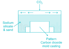
- This process is called sodium silicate moulding process because in this process, the refractory material is coated with a sodium-based binder.
- In this process CO2 gas is passed through the core or mold. The CO2 chemically reacts with the odium silicate to cure or harden the binder.
Which of the following has least percentage of carbon:- a)Malleable iron
- b)Pig iron
- c)Stainless steel
- d)Wrought iron
Correct answer is option 'D'. Can you explain this answer?
Which of the following has least percentage of carbon:
a)
Malleable iron
b)
Pig iron
c)
Stainless steel
d)
Wrought iron
|
|
Prashanth Mehra answered |
Wrought iron is a very pure iron where the iron content is of the order of 99.5%. It is produced by re-melting pig iron and some small amount of silicon, sulphur, or phosphorus may be present. It is tough, malleable and ductile and can easily be forged or welded. It cannot however take sudden shock. Chains, crane hooks, railway couplings and such other components may be made of this iron.
Pig iron is an intermediate product of the iron industry. Pig iron has a very high carbon content, typically 3.8–4.7%, along with silica and other constituents of dross, which makes it very brittle, and not useful directly as a material except for limited applications.
Cast iron is an alloy of iron, carbon and silicon and it is hard and brittle. Carbon content in CI may be within 1.7% to 3% and carbon may be present as free carbon or iron carbide Fe3C. In general, the types of cast iron are (a) grey cast iron and (b) white cast iron (c) malleable cast iron etc
Steel is basically an alloy of iron and carbon in which the carbon content can be less than 1.7% and carbon is present in the form of iron carbide to impart hardness and strength. Two main categories of steel are (a) Plain carbon steel and (b) alloy steel.
Thus, wrought iron is an iron alloy with a very low carbon (less than 0.08%) content in contrast to cast iron.
Quality screw threads are produced by - a)Thread milling
- b) Thread chasing
- c)Thread cutting with single point tool
- d)Thread casting
Correct answer is option 'B'. Can you explain this answer?
Quality screw threads are produced by
a)
Thread milling
b)
Thread chasing
c)
Thread cutting with single point tool
d)
Thread casting
|
|
Anmol Choudhary answered |
Quality screw threads are produced by thread chasing. This process is slow but can provide high quality. Multipoint chasing gives more productivity but at the cost of quality to some extent.
Which of the following is not a casting defect?- a)hot tear
- b)blow hole
- c)scab
- d)decarburization
Correct answer is option 'D'. Can you explain this answer?
Which of the following is not a casting defect?
a)
hot tear
b)
blow hole
c)
scab
d)
decarburization
|
|
Pankaj Joshi answered |
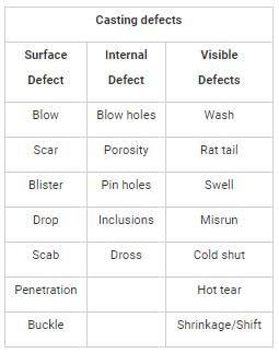
A casting defect is an irregularity in the metal casting process that is undesired.
Classification of casting defects is given as:
For obtaining a cup of diameter 25 mm and height 15 mm by drawing, the size of the round blank should be approximately- a)42 mm
- b)44 mm
- c)46 mm
- d)48 mm
Correct answer is option 'C'. Can you explain this answer?
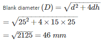
For obtaining a cup of diameter 25 mm and height 15 mm by drawing, the size of the round blank should be approximately
a)
42 mm
b)
44 mm
c)
46 mm
d)
48 mm
|
|
Ashwin Kulkarni answered |
Diameter of cup (d) = 25 mm
Height (h) = 15 mm
In drop forging, forging is done by droping:- a)The work piece at high velocity
- b)The hammer at high velocity
- c)The die with hammer at high velocity
- d)A weight on hammer to hammer to produce the requisite impact
Correct answer is option 'C'. Can you explain this answer?
In drop forging, forging is done by droping:
a)
The work piece at high velocity
b)
The hammer at high velocity
c)
The die with hammer at high velocity
d)
A weight on hammer to hammer to produce the requisite impact
|
|
Dipika Kulkarni answered |
In drop forging, the forging process involves shaping a workpiece by the repeated striking of a hammer against a die. The correct answer is option 'C', which states that forging is done by dropping the die with the hammer at high velocity. Let's understand this answer in detail.
1. Introduction to drop forging:
- Drop forging is a metalworking process used to shape heated metal stock into desired shapes.
- It is a type of forging method where a hammer is used to strike the workpiece onto a die, which results in the required shape.
2. The purpose of drop forging:
- Drop forging is primarily used to produce parts that require high strength, durability, and accuracy.
- It is commonly used in the automotive, aerospace, and construction industries to manufacture components like crankshafts, connecting rods, gears, and axles.
3. Explanation of option 'A' - The workpiece at high velocity:
- This option is incorrect because the workpiece is not dropped at high velocity in drop forging.
- The workpiece is heated to a specific temperature and then placed on the die.
- The hammer, along with the die, is dropped at high velocity onto the workpiece to shape it.
4. Explanation of option 'B' - The hammer at high velocity:
- This option is incorrect because the hammer alone is not dropped at high velocity in drop forging.
- The hammer is used in conjunction with the die and is dropped as a unit onto the workpiece.
- The high velocity of the hammer's impact generates the necessary force to shape the workpiece.
5. Explanation of option 'C' - The die with hammer at high velocity:
- This option is correct because drop forging involves dropping the die with the hammer at high velocity.
- The die is positioned above the workpiece, and the hammer, attached to the die, is lifted to a certain height.
- The hammer is then released, and gravity causes it to fall rapidly, impacting the die and exerting a force on the workpiece.
6. Explanation of option 'D' - A weight on the hammer to produce the requisite impact:
- This option is incorrect because drop forging does not involve placing a weight on the hammer.
- The hammer itself is designed to have enough weight to generate the required impact force.
- The weight and velocity of the falling hammer are carefully controlled to achieve the desired shaping effect on the workpiece.
In conclusion, drop forging involves dropping the die with the hammer at high velocity onto the workpiece. This method allows for the precise shaping of heated metal stock into strong and durable components.
Plug gauge is used to measure:- a)Shaft size
- b)Hole size
- c)Wire thickness
- d)Depth of threads
Correct answer is option 'B'. Can you explain this answer?
Plug gauge is used to measure:
a)
Shaft size
b)
Hole size
c)
Wire thickness
d)
Depth of threads
|
|
Anshu Patel answered |
< b="" />Introduction: < />
A plug gauge is a precision measuring instrument used to measure the size of a hole. It is commonly used in industries such as manufacturing, engineering, and quality control. Plug gauges are designed to provide accurate and reliable measurements of the diameter or size of a hole, ensuring that it meets the required specifications.
< b="" />Explanation: < />
The correct answer to the question is option 'B', which states that a plug gauge is used to measure hole size. Here's why:
< b="" />Shaft size: < />
A plug gauge is not used to measure the size of a shaft. For measuring shaft size, various other tools such as micrometers, calipers, or snap gauges are commonly used. These tools are specifically designed to measure the outer dimensions or diameters of objects like shafts.
< b="" />Wire thickness: < />
A plug gauge is not used to measure wire thickness. For measuring wire thickness, tools like wire gauges or micrometers are commonly used. These tools are specifically designed to measure the diameter or thickness of wires accurately.
< b="" />Depth of threads: < />
A plug gauge is not used to measure the depth of threads. To measure the depth of threads, thread depth gauges or thread micrometers are commonly used. These tools are designed to measure the depth or pitch of threads accurately.
< b="" />Hole size: < />
A plug gauge is primarily used to measure the size of a hole. It consists of a cylindrical body with precisely calibrated dimensions. The gauge is inserted into the hole, and if it fits perfectly without any play or excessive tightness, it indicates that the hole is within the required specifications. The gauge is usually marked with its corresponding size, allowing the user to determine the diameter or size of the hole.
< b="" />Conclusion: < />
In conclusion, a plug gauge is specifically designed to measure the size of a hole. It is not used for measuring shaft size, wire thickness, or depth of threads. By using a plug gauge, manufacturers and engineers can ensure that the holes they produce meet the required specifications, ensuring the quality and functionality of the final product.
Chaplets are used in mould for- a)Enhancing the rate of solidification
- b)Providing additional metal to the casting as it shrinks
- c)Carrying off gates produced during casting
- d)Providing support to the core
Correct answer is option 'D'. Can you explain this answer?
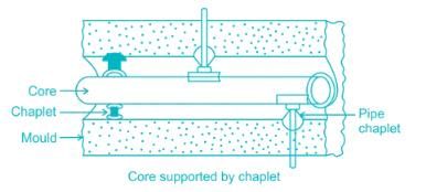
Chaplets are used in mould for
a)
Enhancing the rate of solidification
b)
Providing additional metal to the casting as it shrinks
c)
Carrying off gates produced during casting
d)
Providing support to the core
|
|
Priyanka Shah answered |
Chaplets are used to support the core inside the mould cavity. Chaplet also takes care of its own weight and overcomes the metallostatic forces.
Anodising is:- a)A zinc diffusion process
- b)An oxidising process used for aluminium and magnesium articles
- c)A process used for making thin phosphate coatings on steel to act as a base or primer for enamels and paints
- d)Is the process of coating of zinc by hot dipping
Correct answer is option 'B'. Can you explain this answer?
Anodising is:
a)
A zinc diffusion process
b)
An oxidising process used for aluminium and magnesium articles
c)
A process used for making thin phosphate coatings on steel to act as a base or primer for enamels and paints
d)
Is the process of coating of zinc by hot dipping
|
|
Ayush Chawla answered |
Anodising is an oxidising process used for aluminium and magnesium articles. This process involves the formation of a controlled oxide layer on the surface of the metal, which provides improved corrosion resistance, increased durability, and enhanced aesthetic appearance.
Here is a detailed explanation of the anodising process:
1. Introduction to Anodising:
- Anodising is an electrochemical process that converts the surface of aluminium or magnesium into a protective and decorative oxide layer.
- The process involves immersing the metal in an electrolyte solution and applying an electric current to stimulate the formation of the oxide layer.
2. Formation of Oxide Layer:
- The electrolyte solution typically consists of sulfuric acid or chromic acid, which acts as a medium for the anodising process.
- When a direct current is applied to the metal, oxygen ions from the electrolyte combine with the metal atoms to form a layer of aluminium oxide or magnesium oxide on the surface.
- This oxide layer is porous and adheres tightly to the metal, providing excellent corrosion resistance.
3. Benefits of Anodising:
- Corrosion Resistance: The oxide layer formed through anodising acts as a barrier, preventing the metal from coming into direct contact with corrosive substances. This greatly improves the metal's resistance to corrosion.
- Durability: Anodising increases the hardness and wear resistance of the metal surface, making it more resistant to scratches, abrasion, and fading.
- Aesthetic Appearance: The anodising process allows for the incorporation of various dyes and pigments into the oxide layer, resulting in a wide range of vibrant and durable colors. This makes anodised aluminium and magnesium articles highly desirable for architectural, automotive, and consumer product applications.
4. Other Applications:
- Anodised aluminium is commonly used in architectural components, such as window frames, doors, and curtain walls, due to its combination of corrosion resistance and aesthetic appeal.
- Anodised magnesium is utilized in aerospace and automotive industries for lightweight components that require high strength and corrosion resistance.
In conclusion, anodising is an oxidising process used specifically for aluminium and magnesium articles. It involves the formation of a controlled oxide layer on the metal's surface, providing improved corrosion resistance, durability, and aesthetic appearance.
Sintering is done to- a)Decrease the ductility.
- b)Decrease the final strength.
- c)Increase the final strength.
- d)Increase the porosity.
Correct answer is option 'C'. Can you explain this answer?
Sintering is done to
a)
Decrease the ductility.
b)
Decrease the final strength.
c)
Increase the final strength.
d)
Increase the porosity.
|
|
Anisha Chakraborty answered |
Explanation:
Sintering:
Sintering is a process used to increase the final strength of a material by heating it below its melting point to form a solid mass without melting it completely.
Increasing final strength:
- The main purpose of sintering is to increase the final strength of a material.
- During sintering, the particles in the material are bonded together through diffusion processes, leading to an increase in strength.
How sintering works:
- As the material is heated, the atoms at the surface of the particles diffuse into the adjacent particles, creating bonds between them.
- This bonding results in a denser structure with improved mechanical properties, including higher strength.
Effect on ductility and porosity:
- Sintering can actually decrease the ductility of a material because it leads to a more rigid and dense structure.
- It also helps in reducing porosity by filling in the gaps between particles, thus improving the overall strength of the material.
Therefore, the correct answer is option 'C) Increase the final strength'. Sintering is a crucial process in the manufacturing of various materials, especially in industries like powder metallurgy, ceramics, and additive manufacturing.
Delta iron occurs at which of the following range of temperature?- a)Room temperature
- b)Above melting points
- c)Between 1400°C and 1539°C
- d)Between 900°C and 1400°C
Correct answer is option 'C'. Can you explain this answer?
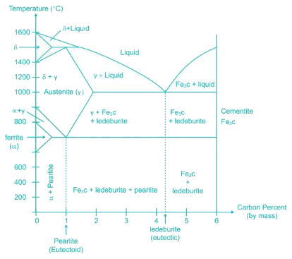
Delta iron occurs at which of the following range of temperature?
a)
Room temperature
b)
Above melting points
c)
Between 1400°C and 1539°C
d)
Between 900°C and 1400°C
|
|
Meera Bose answered |
The three different forms of iron are known as ferrite (α), stable until 910°C, austenite (γ), stable from 910° ‐ 1394°C and delta ferrite (δ), stable from1394° – 1539°C.
Feeler gauges are used for measuring the:- a)Thickness of metal sheet
- b)Clearances between matting parts
- c)Pitch of screw threads
- d)Radius of curvature
Correct answer is option 'B'. Can you explain this answer?
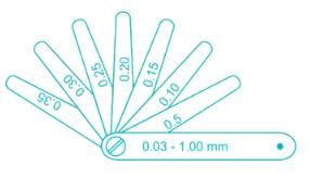
Feeler gauges are used for measuring the:
a)
Thickness of metal sheet
b)
Clearances between matting parts
c)
Pitch of screw threads
d)
Radius of curvature
|
|
Kajal Tiwari answered |
A feeler gauge is a tool used to measure gap widths. Feeler gauges are mostly used in engineering to measure the clearance between two parts.
They consist of a number of small lengths of steel of different thicknesses with measurements marked on each piece.
Which of the following processes come under the indirect compression technique?- a)Rolling
- b)Extrusion
- c)Forging
- d)Rolling & extrusion
Correct answer is option 'B'. Can you explain this answer?
Which of the following processes come under the indirect compression technique?
a)
Rolling
b)
Extrusion
c)
Forging
d)
Rolling & extrusion
|
|
Avantika Sen answered |
Metal working operations may be separated into categories as given below:
a) Direct Compression
b) Indirect compression
c) tension type processes
d) Bending processes
e) shearing processes
- In rolling & forging operations, direct compression forces are used to move metal at right angles to the compression direction
- Indirect compression includes drawing & extrusion, where the metal flows under the action of combined stresses that include a high compressive stress.
Chromium in steel:a) Improves wear resistance, cutting ability and toughnessb) Refines grain size and produces less tendency to carburisation, improves corrosion and heat resistantpropertiesc) Improve cutting ability and reduces hardenabilityd) Gives ductility, toughness, tensile strength and anticorrosion propertiesCorrect answer is option 'A'. Can you explain this answer?
|
|
Anshul Basu answered |
Chromium in steel Increases strength, hardness, hardenability, and toughness, as well as creep resistance and strength at elevated temperatures.
It improves machinability and resistance to corrosion and it intensifies the effects of other alloying elements.
In hot-work steels and high speed steels,
it increases red-hardness properties
It improves machinability and resistance to corrosion and it intensifies the effects of other alloying elements.
In hot-work steels and high speed steels,
it increases red-hardness properties
In the electro-discharge machining process, the work-piece and the electrode are submerged in _____.- a)A dielectric fluid
- b)An abrasive slurry
- c)An electrolytic solution
- d)Vacuum
Correct answer is option 'A'. Can you explain this answer?
In the electro-discharge machining process, the work-piece and the electrode are submerged in _____.
a)
A dielectric fluid
b)
An abrasive slurry
c)
An electrolytic solution
d)
Vacuum
|
|
Ishani Basu answered |
Electrical discharge machining (EDM) is a manufacturing process whereby a desired shape is obtained by using electrical discharges (sparks). Material is removed from the workpiece by a series of rapidly recurring current discharges between two electrodes, separated by a dielectric liquid and subject to an electric voltage. Quite often kerosene based oil is used as dielectric in EDM. The dielectric fluid is circulated through the tool at a pressure of 0.35 N/m2 or less to free it from eroded metal particles. It is circulated through a filter.
The usual value of helix angle of a drill is:- a)10°
- b)20°
- c)30°
- d)60°
Correct answer is option 'C'. Can you explain this answer?
The usual value of helix angle of a drill is:
a)
10°
b)
20°
c)
30°
d)
60°
|
|
Debolina Chavan answered |
Helix angle is the angle between the leading edge of the land and the axis of the drill. It is also known as the spiral angle. The usual value of helix angle of a drill is 30°.

Which bond is commonly used in grinding wheel- a)vitrified bond
- b)silicate bond
- c)shellac bond
- d)resinoid bond
Correct answer is option 'A'. Can you explain this answer?
Which bond is commonly used in grinding wheel
a)
vitrified bond
b)
silicate bond
c)
shellac bond
d)
resinoid bond
|
|
Janhavi Choudhary answered |
Bond commonly used in grinding wheels:
Vitrified bonded (V) wheels:
- Easy to form & compare of Clays & ceramic substances.
- Vitrified wheels are porous, strong, rigid & unaffectedly oils, water or temp. Over the ranges usually encountered in metal cutting that’s why vitrified bond is commonly used bond.
Silicate bonded (s) wheels:
- Use silicate of soda (water glass) as bond material.
- More brittle & not so strong as vitrified wheels.
Resinoid (B) wheels:
Provides shock absorption & elasticity.
Shellac bonded (E) wheels:
Used for making thin but strong wheels possessing some elasticity.
Produce high polish thus used for gridding such parts as camshafts & mill rolls.
Rubber bonded (R) wheels:
For making flexible wheels.
Operates at high speeds up to 16000 ft/mm. They are commonly used for snagging work in foundries & for thin cut off wheels.
Metallic Bonds (M):
For diamond wheels only.
Assume that the two 2 mm thick steel sheets are being sport welded at a current of 5500 A and current - flow time t = 0.15s. Using electrodes 6 mm in diameter, estimate the amount of heat generated in resistance spot welding. (Take RC = 250 μΩ)- a)1032 J
- b)1120 J
- c)995 J
- d)1134 J
Correct answer is option 'D'. Can you explain this answer?
Assume that the two 2 mm thick steel sheets are being sport welded at a current of 5500 A and current - flow time t = 0.15s. Using electrodes 6 mm in diameter, estimate the amount of heat generated in resistance spot welding. (Take RC = 250 μΩ)
a)
1032 J
b)
1120 J
c)
995 J
d)
1134 J
|
|
Saranya Saha answered |
Given data:
- Thickness of each steel sheet (t): 2 mm
- Current (I): 5500 A
- Time (t): 0.15 s
- Diameter of electrodes (d): 6 mm
- Resistance of contact (RC): 250 μΩ
Calculating the heat generated:
1. Calculate the resistance of each spot weld:
- Resistance (R) = RC * t
- R = 250 μΩ * 0.15 s = 37.5 μΩ
2. Calculate the heat generated at each spot weld:
- Heat (Q) = I^2 * R * t
- Q = (5500 A)^2 * 37.5 μΩ * 0.15 s
- Q = 1134 J
Therefore, the amount of heat generated in resistance spot welding is 1134 J.
How many elements are present in tool signature of a single point cutting tool used for turning operation?- a)5
- b)6
- c)7
- d)8
Correct answer is option 'C'. Can you explain this answer?
How many elements are present in tool signature of a single point cutting tool used for turning operation?
a)
5
b)
6
c)
7
d)
8
|
|
Arnav Menon answered |
The tool signature of a single point cutting tool used for turning operations consists of several elements that help define the geometry and characteristics of the tool. These elements are essential for proper tool selection, setup, and machining operations. The correct answer is option 'C', which states that there are seven elements in the tool signature.
The elements present in the tool signature are as follows:
1. Back rake angle:
- The back rake angle is the angle between the face of the tool and a line parallel to the base of the tool.
- It helps in controlling the chip flow and reducing cutting forces.
2. Side rake angle:
- The side rake angle is the angle between the side cutting edge of the tool and a line perpendicular to the base of the tool.
- It helps in controlling the chip flow and reducing cutting forces.
3. End relief angle:
- The end relief angle is the angle between the end cutting edge and a line perpendicular to the base of the tool.
- It provides clearance for the tool during the machining process.
4. Side relief angle:
- The side relief angle is the angle between the side cutting edge and a line perpendicular to the base of the tool.
- It provides clearance for the tool during the machining process.
5. Nose radius:
- The nose radius is the radius formed at the intersection of the face and side cutting edge.
- It helps in reducing cutting forces and improving tool life.
6. Width of the tool:
- The width of the tool refers to the distance between the two side cutting edges.
- It determines the amount of material that can be removed in one pass.
7. Cutting edge angle:
- The cutting edge angle is the angle formed by the side cutting edge and a line perpendicular to the base of the tool.
- It affects the cutting action and chip formation.
These seven elements together define the tool signature of a single point cutting tool used for turning operations. Each element plays a crucial role in determining the tool's performance, chip formation, and the quality of the machined surface. It is important to consider these elements while selecting a cutting tool for a specific turning operation to achieve desired results.
The best size wire (in mm) for measuring effective diameter of a metric thread (included angle is 60°) of 30 mm diameter and 3 mm pitch using two wire method is _______- a)0.75
- b)1.52
- c)1.73
- d)1.3
Correct answer is option 'C'. Can you explain this answer?
The best size wire (in mm) for measuring effective diameter of a metric thread (included angle is 60°) of 30 mm diameter and 3 mm pitch using two wire method is _______
a)
0.75
b)
1.52
c)
1.73
d)
1.3
|
|
Swati Gupta answered |
Best wire size in t
wo wire method
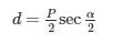
Where P = pitch
α = included angle

= 1.5 sec (30) = 1.732 mm
Following equipments are used in arc welding of material by the use of carbon electrode- a)A.C. welding set
- b)Rectifier
- c)Motor generator
- d)D.C. welding set with straight polarity
Correct answer is option 'D'. Can you explain this answer?
Following equipments are used in arc welding of material by the use of carbon electrode
a)
A.C. welding set
b)
Rectifier
c)
Motor generator
d)
D.C. welding set with straight polarity
|
|
Stuti Bajaj answered |
Answer:
Arc welding is a commonly used welding process that involves the use of an electric arc to join metal pieces together. Carbon electrodes are often used in arc welding for various applications. When using carbon electrodes, a D.C. welding set with straight polarity is the most suitable equipment.
Explanation:
D.C. Welding Set with Straight Polarity:
- A D.C. welding set with straight polarity refers to a direct current (D.C.) welding machine that has a positive electrode and a negative workpiece connection.
- In arc welding with carbon electrodes, the carbon electrode acts as the positive electrode while the workpiece acts as the negative electrode. This configuration is known as straight polarity or direct current electrode positive (DCEP).
- Straight polarity is preferred when using carbon electrodes because it provides better control over the welding process and improves arc stability. It also reduces the electrode consumption and helps in preventing overheating of the electrode.
Other Equipment Options:
a) A.C. Welding Set:
- A.C. welding sets are not suitable for arc welding with carbon electrodes. A.C. welding sets provide alternating current, which is not ideal for maintaining a stable arc with carbon electrodes. The arc tends to flicker and become unstable, making it difficult to achieve good weld quality.
b) Rectifier:
- A rectifier is a device used to convert alternating current (A.C.) into direct current (D.C.). While rectifiers are used in some welding machines, they are not specifically designed for arc welding with carbon electrodes.
c) Motor Generator:
- A motor generator is a device that converts mechanical energy into electrical energy. While motor generators can be used to generate direct current for welding, they are not specifically designed for arc welding with carbon electrodes.
Therefore, the correct equipment option for arc welding using carbon electrodes is a D.C. welding set with straight polarity. This equipment provides the necessary control and stability required for successful arc welding with carbon electrodes.
Which of the following is not a gear finishing process?- a)Gear hobbing
- b)Gear shaving
- c)Gear lapping
- d)Gear grinding
Correct answer is option 'A'. Can you explain this answer?
Which of the following is not a gear finishing process?
a)
Gear hobbing
b)
Gear shaving
c)
Gear lapping
d)
Gear grinding
|
|
Sinjini Bose answered |
Gear hobbing is not a gear finishing process.
Gear hobbing is a gear manufacturing process that involves the use of a hob, which is a cylindrical cutting tool with helical teeth. During gear hobbing, the hob is mounted on a hobbing machine and it rotates while the gear blank is slowly fed against it. As the hob and gear blank rotate, the teeth of the hob gradually cut into the blank, creating the desired gear teeth.
Gear hobbing is a primary gear manufacturing process, not a finishing process. It is typically used to generate the initial gear teeth profile before any finishing operations are performed. The process is capable of producing gears with high accuracy and good surface finish, but it may leave some residual imperfections on the gear teeth surface.
Gear finishing processes, on the other hand, are used to improve the surface finish and dimensional accuracy of gears that have already been formed. These processes are often performed after gear hobbing or other primary gear manufacturing processes. Some common gear finishing processes include gear shaving, gear lapping, and gear grinding.
Gear shaving is a gear finishing process that involves removing a thin layer of material from the gear teeth surface using a shaving cutter. This process helps to improve the surface finish, reduce gear noise, and ensure proper gear tooth contact.
Gear lapping is another gear finishing process that uses a lapping tool, typically a cast iron or bronze wheel, along with a fine abrasive paste to remove small amounts of material from the gear teeth surface. This process helps to improve the surface finish, eliminate any remaining imperfections, and ensure proper gear meshing.
Gear grinding is a gear finishing process that involves the use of a grinding wheel to remove material from the gear teeth surface. This process is used to achieve high precision and tight tolerances, as well as improve the surface finish and gear tooth profile.
In summary, gear hobbing is not a gear finishing process but a primary gear manufacturing process. Gear finishing processes, such as gear shaving, gear lapping, and gear grinding, are performed after the gears have been formed to improve their surface finish and dimensional accuracy.
According to Indian standard specifications 50H7g6 means that:1. Actual size is 50 mm2. Tolerance grade for hole is 73. Tolerance grade for shaft is 6Which of the statements are correct?- a)1 and 2
- b)1, 2 and 3
- c)2 and 3
- d)None of these
Correct answer is option 'C'. Can you explain this answer?
According to Indian standard specifications 50H7g6 means that:
1. Actual size is 50 mm
2. Tolerance grade for hole is 7
3. Tolerance grade for shaft is 6
Which of the statements are correct?
a)
1 and 2
b)
1, 2 and 3
c)
2 and 3
d)
None of these
|
|
Manoj Pillai answered |
50H7g6 means basic size is 50 mm and the tolerance grade for the hole is 7 and for the shaft is 6.
Basic Size: The size with reference to which the limits of size are fixed.
Actual Size: Actual measured dimension of the part.
Here 50 is the basic size, not actual size.
Generally least count of the commonly used Vernier is:- a)0.1 mm
- b)0.01 mm
- c)0.02 mm
- d)0.2 mm
Correct answer is option 'C'. Can you explain this answer?
Generally least count of the commonly used Vernier is:
a)
0.1 mm
b)
0.01 mm
c)
0.02 mm
d)
0.2 mm
|
|
Dhruba Jain answered |
Least count is said to be the smallest value that can be measured by a measuring instrument. A Vernier scale on calliper may have a least count of 0.02 mm while a micrometre may have a least count of 0.001 mm.
Enlarging an existing circular hole with a rotating single point tool is called:- a)Boring
- b)Drilling
- c)Reaming
- d)Internal turning
Correct answer is option 'A'. Can you explain this answer?
Enlarging an existing circular hole with a rotating single point tool is called:
a)
Boring
b)
Drilling
c)
Reaming
d)
Internal turning
|
|
Saikat Choudhary answered |
Boring is the process of enlarging an existing circular hole with a rotating single point tool. It is commonly used in machining operations to achieve precise dimensions and smooth surface finishes. The process involves removing material from the inner diameter of a workpiece to create a larger hole or cylinder.
Boring is typically performed on a lathe or a boring machine. The rotating tool, known as a boring bar, is mounted on the machine and inserted into the existing hole. The workpiece is held securely in place while the tool rotates and removes material.
The process of boring can be divided into the following steps:
1. Selecting the appropriate tool: The boring bar is chosen based on the desired size and accuracy of the hole. It should have the necessary rigidity and cutting capabilities to efficiently remove material.
2. Securing the workpiece: The workpiece is securely clamped or mounted on the machine to prevent any movement during the boring process. This ensures accuracy and stability.
3. Centering the tool: The boring bar is positioned concentrically with the existing hole to ensure proper alignment. This is crucial for achieving accurate results and preventing any deviation from the desired dimensions.
4. Rotating the tool: The machine is activated, causing the boring bar to rotate. As it rotates, the cutting edge of the tool makes contact with the inner surface of the hole, gradually removing material and enlarging the diameter.
5. Monitoring the process: The operator closely monitors the boring process to ensure the desired dimensions are achieved. This may involve measuring the diameter of the hole at regular intervals using precision instruments.
6. Finishing touches: Once the desired size is reached, the operator may use additional tools or techniques to achieve a smooth surface finish. This could involve using a reamer or honing tool to remove any remaining imperfections.
Overall, the process of boring is essential in various industries, including automotive, aerospace, and manufacturing. It allows for precise hole enlargement and ensures the desired dimensional accuracy and surface finish.
The preferred option for holding an odd-shaped workpiece in a center lathe is- a)live and dead centres
- b)three jaw chuck
- c)lathe dog
- d)four jaw chuck
Correct answer is option 'D'. Can you explain this answer?
The preferred option for holding an odd-shaped workpiece in a center lathe is
a)
live and dead centres
b)
three jaw chuck
c)
lathe dog
d)
four jaw chuck
|
|
Asha Basu answered |
Standard work holding devices used in lathe operations are:
a) Chucks b) Centres
c) Carriers (also known as driving dogs) d) Face plates
e) Mandrels
Chucks:
Four jaw chuck: A chuck with jaws that open & close independently. Independent chucks can be adjusted to accommodate irregularly shaped work pieces such as odd items square in shape.
Three jaw chuck: Used to hold round & hexagonal work.
Collect chuck: Most accurate chuck & is used for high precision work and small tools.
Magnetic chucks: are used to hold iron or steel parts that are too thin (or) that may be damaged in conventional chuck.
Faceplates: Used to hold work that is too large or such a such a shape that it can not be held in a chuck or between centres.
For the same material, powder metallurgy process is superior to casting for- a)Better strength of the finished product
- b)Better control over the density of product
- c)Making larger products
- d)Making parts with wide variations of thickness at different sections.
Correct answer is option 'B'. Can you explain this answer?
For the same material, powder metallurgy process is superior to casting for
a)
Better strength of the finished product
b)
Better control over the density of product
c)
Making larger products
d)
Making parts with wide variations of thickness at different sections.
|
|
Nandita Chakraborty answered |
In powder metallurgy, by varying the compaction force the density of the product can be varied. That’s why the powder metallurgy is superior to casting.
Which of the following is the not a natural abrasive?- a)Garnet
- b)Emery
- c)Boron-carbide
- d)Corundum
Correct answer is option 'C'. Can you explain this answer?
Which of the following is the not a natural abrasive?
a)
Garnet
b)
Emery
c)
Boron-carbide
d)
Corundum
|
|
Simran Mukherjee answered |
Abrasives are classified into two categories:
Natural Abrasives:
Garnet
Corundum
Emery (impure corundum)
Calcite (calcium carbonate)
Diamond dust
Novaculite
Pumice
Rouge
Sand
Sandstone
Tripoli
Powdered feldspar
Staurolite
Synthetic Abrasives:
Boron carbide
Borazon (cubic boron nitride or CBN)
Ceramic
Ceramic aluminium oxide
Ceramic iron oxide
Dry ice
Glass powder
Steel abrasive
Zirconia alumina
Slags
Which of the following is used as a dielectric medium in EDM?- a)Salt solution
- b)Silicon carbide solution
- c)AI2O3 solution
- d)Kerosene
Correct answer is option 'D'. Can you explain this answer?
Which of the following is used as a dielectric medium in EDM?
a)
Salt solution
b)
Silicon carbide solution
c)
AI2O3 solution
d)
Kerosene
|
|
Rithika Kaur answered |
In EDM a fluid is used to act as a dielectric and to help carry away debris. Quite often kerosene based oil is used as dielectric in EDM. The dielectric fluid is circulated through the tool at a pressure of 0.35 N/m2 or less to free it from eroded metal particles, it is circulated through a filter.
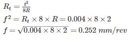
A hacksaw blade cuts on the:- a)Forward stroke
- b)Return stroke
- c)Both forward and return stroke
- d)None of these
Correct answer is option 'A'. Can you explain this answer?
A hacksaw blade cuts on the:
a)
Forward stroke
b)
Return stroke
c)
Both forward and return stroke
d)
None of these
|
|
Gowri Sharma answered |
In hacksaw blade, teeth face forward. The saws are designed so the blade will cut when it’s pushed (the forward stroke) rather than when pulled.
If the Taylor’s tool life exponent n is 0.25 and the tool changing time is 2 min, the tool life (in seconds) for maximum production rate is- a)200
- b)360
- c)120
- d)180
Correct answer is option 'B'. Can you explain this answer?
If the Taylor’s tool life exponent n is 0.25 and the tool changing time is 2 min, the tool life (in seconds) for maximum production rate is
a)
200
b)
360
c)
120
d)
180
|
|
Anuj Verma answered |
for Maximum production rate or Minimum production time,
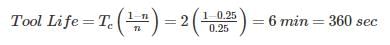
Match the following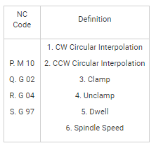
- a)P-4, Q-1, R-5, S-6
- b)P-3, Q-1, R-5, S-6
- c)P-3, Q-2, R-6, S-5
- d)P-4, Q-2, R-5, S-3
Correct answer is option 'B'. Can you explain this answer?
Match the following
a)
P-4, Q-1, R-5, S-6
b)
P-3, Q-1, R-5, S-6
c)
P-3, Q-2, R-6, S-5
d)
P-4, Q-2, R-5, S-3
|
|
Shreya Choudhury answered |
Important G codes
G 00 – Rapid Transverse
G 01 – Linear Interpolation
G 02 – CW Circular Interpolation
G 03 – CCW Circular Interpolation
G 04 – Dwell
G – 97 – Spindle Speed
Important M codes
M 00 – Program Stop
M 03 – Spindle (CW)
M 04 – Spindle (CCW)
M 05 – Spindle Stop
M 08 – Coolant on
M 09 – Coolant off
M 10 – Clamp on
M 11 – Clamp off
M 02 or M 30 – Program stop, reset to start.
In a single pass rolling operation, if the coefficient of friction is doubled keeping other parameters same, the percentage change in draft will be _______ %- a)100
- b)200
- c)300
- d)50
Correct answer is option 'C'. Can you explain this answer?
In a single pass rolling operation, if the coefficient of friction is doubled keeping other parameters same, the percentage change in draft will be _______ %
a)
100
b)
200
c)
300
d)
50
|
|
Jay Menon answered |
**Explanation:**
In a rolling operation, the draft is defined as the reduction in thickness of the workpiece as it passes through the rolling mill. The draft is influenced by various parameters, including the coefficient of friction between the rolls and the workpiece.
When the coefficient of friction is doubled, it means that the frictional force between the rolls and the workpiece is increased. This increased frictional force will result in a higher resistance to the motion of the workpiece through the rolling mill. As a result, the workpiece will experience a higher compressive force during the rolling process.
The draft in a rolling operation is directly proportional to the compressive force applied to the workpiece. Therefore, when the coefficient of friction is doubled, the compressive force acting on the workpiece will also be doubled. This increased compressive force will result in a higher reduction in thickness of the workpiece, leading to an increase in draft.
To calculate the percentage change in draft, we can use the following formula:
% Change in draft = (New draft - Initial draft) / Initial draft * 100
Since the initial draft is not given in the question, we can assume it to be a reference value, such as 100 units. Let's calculate the new draft when the coefficient of friction is doubled:
New draft = Initial draft + (Change in draft)
Since the coefficient of friction is doubled, the change in draft can be calculated as:
Change in draft = (2 * Initial draft) - Initial draft = Initial draft
Therefore, the new draft will be:
New draft = Initial draft + Initial draft = 2 * Initial draft
Now, let's substitute the values in the percentage change formula:
% Change in draft = (2 * Initial draft - Initial draft) / Initial draft * 100
Simplifying the equation, we get:
% Change in draft = Initial draft / Initial draft * 100 = 100%
Therefore, the percentage change in draft when the coefficient of friction is doubled is 100%. This means that the draft will increase by 100% when the coefficient of friction is doubled.
Hence, the correct answer is option C) 300%.
Gear hobbing process is faster than milling because- a)Indexing time is less
- b)Hob rotates faster
- c)Work rotates faster
- d)Several teeth cut at a time
Correct answer is option 'D'. Can you explain this answer?
Gear hobbing process is faster than milling because
a)
Indexing time is less
b)
Hob rotates faster
c)
Work rotates faster
d)
Several teeth cut at a time
|
|
Sandeep Sengupta answered |
Gear hobbing is a multi point machining process in which gear teeth are progressively generated by a series of cuts with a hob. Both the hob and the work piece revolve constantly as the hob is fed across the face width of the gear blank.
Gear milling is a multi point machining process in which individual tooth spacing are created by a rotating multi edge cutter having a cross-section similar to that of the generated teeth (in volute). After cutting each space, the gear is returned to its original position, and the gear blank is indexed for the next cut.
So hobbing is faster than milling because several teeth cut at a time.
In gas tungsten are welding process, the material coated on pure tungsten electron to enhance its current carrying capacity is- a)Titanium
- b)Manganese
- c)Radium
- d)Thorium
Correct answer is option 'D'. Can you explain this answer?
In gas tungsten are welding process, the material coated on pure tungsten electron to enhance its current carrying capacity is
a)
Titanium
b)
Manganese
c)
Radium
d)
Thorium
|
|
Raghavendra Dasgupta answered |
- Pure tungsten electrode offers shorter life than coated electrodes because of rapid wear and tear of pure tungsten electrode owing to thermal damage caused by their low current carrying capacity.
- Pure tungsten electrodes are frequently coated oxides of Th, Zr, La & Ce. These oxides are expected to perform two important function.
1. increasing arc stability
2. Increasing the current carrying capacity of the electrodes.
Chapter doubts & questions for Manufacturing Engineering - SSC JE Mechanical Mock Test Series 2026 2025 is part of Mechanical Engineering exam preparation. The chapters have been prepared according to the Mechanical Engineering exam syllabus. The Chapter doubts & questions, notes, tests & MCQs are made for Mechanical Engineering 2025 Exam. Find important definitions, questions, notes, meanings, examples, exercises, MCQs and online tests here.
Chapter doubts & questions of Manufacturing Engineering - SSC JE Mechanical Mock Test Series 2026 in English & Hindi are available as part of Mechanical Engineering exam.
Download more important topics, notes, lectures and mock test series for Mechanical Engineering Exam by signing up for free.
SSC JE Mechanical Mock Test Series 2026
3 videos|1 docs|55 tests
|
|
© EduRev
|
Education Revolution
|


|


Signup to see your scores
go up within 7 days!
Access 1000+ FREE Docs, Videos and Tests
Takes less than 10 seconds to signup