


All questions of Control Systems for Electronics and Communication Engineering (ECE) Exam
Can you explain the answer of this question below:
The sum of the gains of the feedback paths in the signal flow graph shown in fig. is
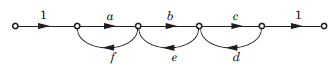 A: af + be + cd
B: af + be + cd+abef + bcdeC: af + be + cd + abef + abcdefD: af + be + cd + cbef + bcde + abcdefThe answer is a.

|
Phanindra Varma N answered |
Answer is B because ut can form only individual loop gains

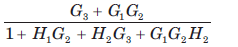
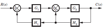
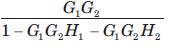
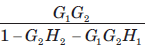
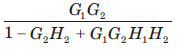
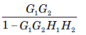
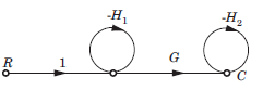
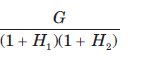
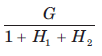
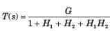
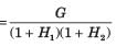
The block diagram of a system is shown in fig.The closed loop transfer function of this system is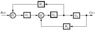
a)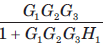 b)
b) 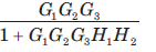 c)
c) 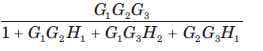
d) 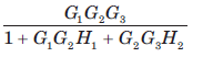
Correct answer is 'D'. Can you explain this answer?
a)
b)
c)
d)
Correct answer is 'D'. Can you explain this answer?
|
|
Nitya Ahuja answered |
Consider the block diagram as SFG. There are two feedback loop -G1G2H1 and -G2G3H2 and one forward path G1G2 G3 . So (D) is correct option.
The gain C(s)/R(s) of the signal flow graph shown in fig.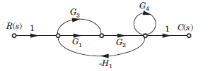
- a)
- b)
- c)
- d)
Correct answer is option 'B'. Can you explain this answer?
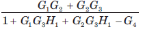
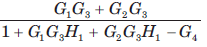
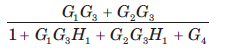
The gain C(s)/R(s) of the signal flow graph shown in fig.
a)
b)
c)
d)

|
Pie Academy answered |
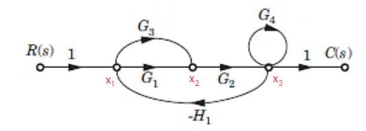
X1 = 1 - H1
X2 = (G1 + G3) X1 - X3H1
X3 = X2G2 + G4
Linear system obeys- a)reciprocity theorem
- b)principle of maximum power transfer
- c)both (a) and (b)
- d)none of the above
Correct answer is option 'C'. Can you explain this answer?
Linear system obeys
a)
reciprocity theorem
b)
principle of maximum power transfer
c)
both (a) and (b)
d)
none of the above
|
|
Sanvi Kapoor answered |
Linear system obeys both reciprocity theorem and principle of maximum power transfer.
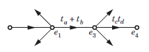
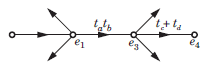
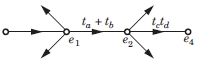
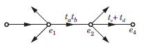
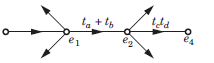
For the signal flow graph shown in fig. an equivalent graph is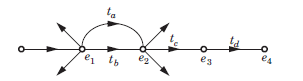
- a)
- b)
- c)
- d)
Correct answer is option 'C'. Can you explain this answer?
For the signal flow graph shown in fig. an equivalent graph is
a)
b)
c)
d)

|
Aim It Academy answered |
While writing the transfer function of this signal flow graph,
e2= tae1 + tbe1 = (ta+ tb) e1
Then, signal flow graph will lokk like this:
In the signal flow graph of figure y/x equalsa) 3b) 2c) 5/2d) None of the aboveCorrect answer is option 'B'. Can you explain this answer?
|
|
Aditya Deshmukh answered |
The answer is b.
P1 = 5 x 2 x 1 = 10
P1 = 5 x 2 x 1 = 10
L1 = - 4
Y/X = 10/1-(-4) = 2
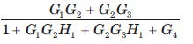
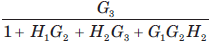
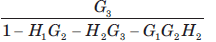
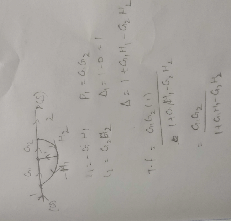
For the system shown in fig. transfer function C(s) R(s) is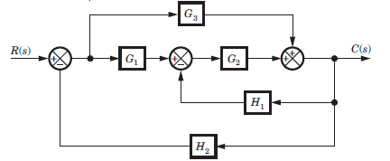
- a)
- b)
- c)
- d)
Correct answer is option 'B'. Can you explain this answer?
For the system shown in fig. transfer function C(s) R(s) is
a)
b)
c)
d)

|
Gate Gurus answered |
Consider the block diagram as a SFG. Two forward path G1G2 and G3 and three loops -G1G2 H2, -G2H1, -G3 H2
There are no nontouching loop. So (B) is correct.
There are no nontouching loop. So (B) is correct.
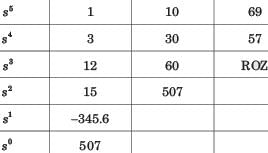
A Routh table is shown in fig. The location of pole on RHP, LHP and imaginary axis are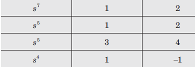
- a)1, 2, 4
- b)1, 6, 0
- c)1, 0, 6
- d)None of the above
Correct answer is 'A'. Can you explain this answer?
A Routh table is shown in fig. The location of pole on RHP, LHP and imaginary axis are
a)
1, 2, 4
b)
1, 6, 0
c)
1, 0, 6
d)
None of the above

|
Jaya Yadav answered |
If the system is given with the unbounded input then nothing can be clarified for the stability of the system.
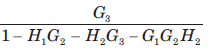
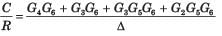
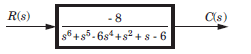
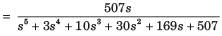
For the block diagram shown in fig. the numerator of transfer function is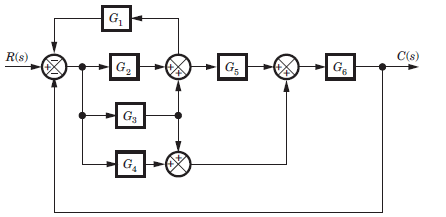
- a)
- b)
- c)
- d)none of these
Correct answer is option 'A'. Can you explain this answer?
For the block diagram shown in fig. the numerator of transfer function is
a)
b)
c)
d)
none of these
|
|
Zoya Sharma answered |
SFG
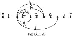
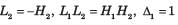
P1 = G2G5G6 , P2 = G3G5G6, P3 = G3G6 , P4 = G4G6
If any path is deleted, there would not be any loop.
Hence Δ1 = Δ2 = Δ3 = Δ4 = 1
P1 = G2G5G6 , P2 = G3G5G6, P3 = G3G6 , P4 = G4G6
If any path is deleted, there would not be any loop.
Hence Δ1 = Δ2 = Δ3 = Δ4 = 1
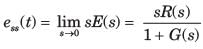
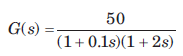
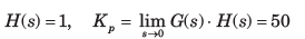
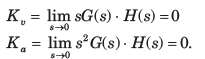
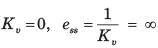
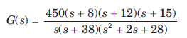
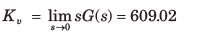
A ufb control system has a forward path transfer function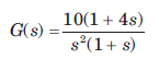 If the system is subjected to an input r(t) = 1 + t + 1/2 t2 , t > 0the steady state error of the system will be
- a)0
- b)0.1
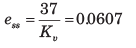
- c)10
- d)∞
Correct answer is option 'C'. Can you explain this answer?
A ufb control system has a forward path transfer function
If the system is subjected to an input r(t) = 1 + t + 1/2 t2 , t > 0the steady state error of the system will be
a)
0
b)
0.1
c)
10
d)
∞
|
|
Lekshmi Kulkarni answered |
System is type 2. Therefore error due to 1+t would be zero and due to  would be
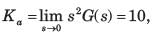
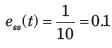
Note that you may calculate error from the formula
would be Note that you may calculate error from the formula
The principle of homogeneity and superposition are applied to:a)Linear time variant systemsb)Nonlinear time invariant systemsc)Linear time invariant systemsd)Nonlinear time invariant systemsCorrect answer is 'C'. Can you explain this answer?
|
|
Aditya Deshmukh answered |
Superposition theorem states that for two signals, additive and homogeneity property must be satisfied and that is applicable for the Linear time variant (LTI) systems.
Assertion (A): Closed loop control systems are known as feedback control systems.
Reason (R): In closed loop control systems, the control action is dependent on the desired output.- a)Both A and R are true and R is a correct explanation of A.
- b)Both A and R are true but R is not a correct explanation of A.
- c)A is true but R is false.
- d)A is false but R is true.
Correct answer is option 'A'. Can you explain this answer?
Assertion (A): Closed loop control systems are known as feedback control systems.
Reason (R): In closed loop control systems, the control action is dependent on the desired output.
Reason (R): In closed loop control systems, the control action is dependent on the desired output.
a)
Both A and R are true and R is a correct explanation of A.
b)
Both A and R are true but R is not a correct explanation of A.
c)
A is true but R is false.
d)
A is false but R is true.
|
|
Sanvi Kapoor answered |
- In closed loop system there is the presence of a feedback path and this feedback path has connected from output of the system to the input of the system.
- The whole operation is controlled by the output of the system.
The output of the feedback control system must be a function of:
- a)Reference input
- b)Reference output
- c)Output and feedback signal
- d)Input and feedback signal
Correct answer is option 'D'. Can you explain this answer?
The output of the feedback control system must be a function of:
a)
Reference input
b)
Reference output
c)
Output and feedback signal
d)
Input and feedback signal
|
|
Athira Reddy answered |
Explanation: In a feedback control system, the output is determined by a combination of the input signal and the feedback signal. The input signal is the desired output or reference, while the feedback signal is a portion of the actual output that is fed back into the system to compare with the input. This comparison helps the system to adjust its output to minimize the error between the input and the actual output. By considering both the input and feedback signals, the system can continuously adapt and achieve the desired output.
Assertion (A): If the number of zeros are less than the number of poles (i.e. Z < P), we say that there are zeros at infinity and the order of such zeros is P-Z
Reason (R): The value of the transfer function becomes zero for s tends to zero.- a)Both A and R are true and R is a correct explanation of A.
- b)Both A and R are true but R is not a correct explanation of A.
- c)A is true but R is false.
- d)A is false but R is true.
Correct answer is option 'C'. Can you explain this answer?
Assertion (A): If the number of zeros are less than the number of poles (i.e. Z < P), we say that there are zeros at infinity and the order of such zeros is P-Z
Reason (R): The value of the transfer function becomes zero for s tends to zero.
Reason (R): The value of the transfer function becomes zero for s tends to zero.
a)
Both A and R are true and R is a correct explanation of A.
b)
Both A and R are true but R is not a correct explanation of A.
c)
A is true but R is false.
d)
A is false but R is true.

|
Uday Kumar answered |
For Z < P,
∴ Here, number of zeros = 1 and no. of poles = 2
∴ P - Z = 1
When s →∞, transfer function becomes zero. Thus, there is one zero (P - Z = 1) at infinity. Thus, assertion is true.
Since value of transfer function becomes zero as s →∞ therefore, reason is false.
∴ Here, number of zeros = 1 and no. of poles = 2
∴ P - Z = 1
When s →∞, transfer function becomes zero. Thus, there is one zero (P - Z = 1) at infinity. Thus, assertion is true.
Since value of transfer function becomes zero as s →∞ therefore, reason is false.
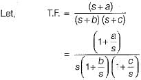
Consider the List I and List II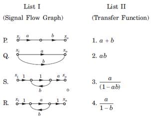 The correct match is
- a)2 1 3 4
- b)2 1 4 3
- c)1 2 4 3
- d)1 2 3 4
Correct answer is option 'B'. Can you explain this answer?
Consider the List I and List II
The correct match is
a)
2 1 3 4
b)
2 1 4 3
c)
1 2 4 3
d)
1 2 3 4

|
Om Pillai answered |
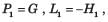
P. P1 = ab, Δ = 1, L = 0 ,T = ab
Q1 P1 = a, P2 = 6 , Δ = 1, L = Δk = 0,T = a+b
R. P1 = a, L1 = b, Δ = 1 - b, Δ1 =1,
S. P1 = a, L1 = ab, Δ = 1 - ab, Δ1 = 1,
Q1 P1 = a, P2 = 6 , Δ = 1, L = Δk = 0,T = a+b
R. P1 = a, L1 = b, Δ = 1 - b, Δ1 =1,
S. P1 = a, L1 = ab, Δ = 1 - ab, Δ1 = 1,
The negative feedback closed-loop system was subjected to 15V. The system has a forward gain of 2 and a feedback gain of 0.5. Determine the output voltage and the error voltage.- a)15V, 10V
- b)6V, 5V
- c)15V, 7.5V
- d)5V, 10V
Correct answer is option 'C'. Can you explain this answer?
The negative feedback closed-loop system was subjected to 15V. The system has a forward gain of 2 and a feedback gain of 0.5. Determine the output voltage and the error voltage.
a)
15V, 10V
b)
6V, 5V
c)
15V, 7.5V
d)
5V, 10V

|
Starcoders answered |
The negative feedback closed-loop system, subjected to 15V, has a forward gain of 2 and a feedback gain of 0.5.
- The output voltage is calculated as the product of the forward gain and the effective input voltage.
- The effective input voltage is the difference between the input voltage and the feedback voltage.
To find the output voltage:
- Calculate the feedback voltage: Output Voltage multiplied by Feedback Gain.
- Effective input = Input voltage - Feedback voltage.
- Output voltage = Forward gain x Effective input voltage.
After solving, the output voltage is 15V and the error voltage is 7.5V.


The most commonly used input signal(s) in control system is/are- a)ramp or velocity function
- b)step function
- c)accelerating function
- d)all of the above
Correct answer is option 'B'. Can you explain this answer?
The most commonly used input signal(s) in control system is/are
a)
ramp or velocity function
b)
step function
c)
accelerating function
d)
all of the above
|
|
Sarita Yadav answered |
A step function is commonly used as a input signal in a control system because:
- IF we go through first order system, here we calculate steady-state error by providing input function then we got zero steady-state error.
- Actually in step function, output follows input always that means steady error is minimum.
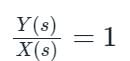
For the system shown in the figure, Y(s)/X(s) = _________. (Answer in integer )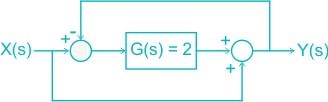
Correct answer is between '0.95,1.05'. Can you explain this answer?
For the system shown in the figure, Y(s)/X(s) = _________. (Answer in integer )

|
Cstoppers Instructors answered |
The circuit is redrawn as shown:
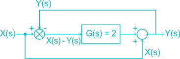
[X(s) – Y(s)] G(s) + X(s) = Y(s)
Given G(s) = 2
(X(s) – Y(s)) 2 + X(s) = Y(s)
= 2 X(s) + X(s) = Y(s) + 2Y(s)
= 3 X(s) = 3 Y(s)
Assuming zero initial condition, the response y(t) of the system given below to a unit step input u(t) is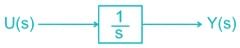
- a)u(t)
- b)t.u(t)
- c)t2/2.u(t)
- d)e-tu(t)
Correct answer is option 'B'. Can you explain this answer?
Assuming zero initial condition, the response y(t) of the system given below to a unit step input u(t) is
a)
u(t)
b)
t.u(t)
c)
t2/2.u(t)
d)
e-tu(t)
|
|
Luminary Institute answered |
Laplace transform of u(t) is given by
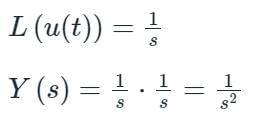
Taking Inverse Laplace transform
y(t) = t.u(t)
Which of the following is not true regarding an open loop control system?- a)Highly affected by non-linearities.
- b)Open loop systems are inaccurate.
- c)These are not reliable.
- d)The effect of parameter variation and internal noise is less.
Correct answer is option 'D'. Can you explain this answer?
Which of the following is not true regarding an open loop control system?
a)
Highly affected by non-linearities.
b)
Open loop systems are inaccurate.
c)
These are not reliable.
d)
The effect of parameter variation and internal noise is less.
|
|
Rahul Banerjee answered |
The effect of parameter variation and internal noise is more in an open loop system.
The step response of a system is given by
c(t) = 1 + 0.25 e-50t - 1.25e-10t
The steady state gain of the transfer function in time constant form will be- a)1
- b)7
- c)-5
- d)-7
Correct answer is option 'A'. Can you explain this answer?
The step response of a system is given by
c(t) = 1 + 0.25 e-50t - 1.25e-10t
The steady state gain of the transfer function in time constant form will be
c(t) = 1 + 0.25 e-50t - 1.25e-10t
The steady state gain of the transfer function in time constant form will be
a)
1
b)
7
c)
-5
d)
-7

|
Ritika Menon answered |
Given, c(t) = 1 + 0.25 e-50t - 1.25e-10t
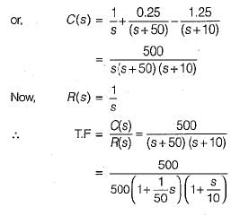
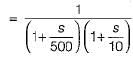
Thus,C(s)/R(s) is in time constant form having steady state gain = 1.
Thus,C(s)/R(s) is in time constant form having steady state gain = 1.
Assertion (A): The control system which operates on the time basis is an open loop system.
Reason (R): A field control d.c. motor is an example of open loop system.- a)Both A and R are true and R is the correct explanation of A.
- b)Both A and R are true but R is not the correct explanation of A.
- c)A is true but R is false.
- d)A is false but R is true.
Correct answer is option 'B'. Can you explain this answer?
Assertion (A): The control system which operates on the time basis is an open loop system.
Reason (R): A field control d.c. motor is an example of open loop system.
Reason (R): A field control d.c. motor is an example of open loop system.
a)
Both A and R are true and R is the correct explanation of A.
b)
Both A and R are true but R is not the correct explanation of A.
c)
A is true but R is false.
d)
A is false but R is true.

|
Sandeep Sen answered |
The control system which operates on the time basis is an open loop system. For example, in automatic control of traffic, the time for each lamp (red, yellow and green) is fixed. The operation of each lamp does not depends upon the density of the traffic but depends upon the fixed time. Hence, assertion is true.
Reason is also true but, it is not the correct explanation of assertion.
Reason is also true but, it is not the correct explanation of assertion.
A control system is said to be robust when- a)it has low sensitivities
- b)it is stable over a wide range of parameter variation
- c)both (a) and (b)
- d)neither (a) nor (b)
Correct answer is option 'C'. Can you explain this answer?
A control system is said to be robust when
a)
it has low sensitivities
b)
it is stable over a wide range of parameter variation
c)
both (a) and (b)
d)
neither (a) nor (b)

|
Bhaskar Unni answered |
Robustness is an important characteristic of a control system, as it determines how well the system can perform in the presence of uncertainties and disturbances. A robust control system is able to maintain stability and optimal performance over a wide range of parameter variations.
Sensitivity:
Sensitivity refers to how the system responds to changes in its parameters. A control system with low sensitivities means that it is less affected by variations in its parameters. In other words, small changes in the system's parameters do not result in significant changes in the system's performance. Low sensitivities are desirable because they indicate that the system is less vulnerable to uncertainties and disturbances.
Stability:
Stability is a fundamental requirement for any control system. A stable control system maintains a desired output in the presence of disturbances and uncertainties. It ensures that the system does not exhibit oscillatory or diverging behavior, which can lead to instability. A control system that is stable over a wide range of parameter variation is considered to be robust.
Robustness:
The combination of low sensitivities and stability makes a control system robust. When a control system has low sensitivities, it means that it is not highly influenced by parameter variations. This allows the system to maintain its desired performance even when there are changes in the parameters. Additionally, when a control system is stable over a wide range of parameter variation, it means that it can adapt to different operating conditions without losing stability. This adaptability is a key characteristic of a robust control system.
Conclusion:
In conclusion, a control system is said to be robust when it has both low sensitivities and stability over a wide range of parameter variation. This means that the system is able to maintain its desired performance despite uncertainties and disturbances. Robust control systems are desirable because they are more reliable and can handle a variety of operating conditions.
As compared to a closed loop system, an open loop system is- a)slow and more reliable
- b)fast and more reliable
- c)fast and less reliable
- d)slow and less reliable
Correct answer is option 'C'. Can you explain this answer?
As compared to a closed loop system, an open loop system is
a)
slow and more reliable
b)
fast and more reliable
c)
fast and less reliable
d)
slow and less reliable
|
|
Sanvi Kapoor answered |
The main difference between an open-loop system and a closed-loop system is that the closed-loop system has the ability to self-correct while the open-loop system doesn't. Consequently, closed-loop systems are often called feedback control systems while open-loop systems are also known as non-feedback controls.
As compared to a closed loop system, an open loop system is
- a)more stable but less accurate
- b)less stable as well as less accurate
- c)more stable as well as more accurate
- d)less stable but more accurate
Correct answer is option 'A'. Can you explain this answer?
As compared to a closed loop system, an open loop system is
a)
more stable but less accurate
b)
less stable as well as less accurate
c)
more stable as well as more accurate
d)
less stable but more accurate
|
|
Sanvi Kapoor answered |
As compared to closed loop system an open loop control system is more stable as all its roots are in left half of s plane only, but it less accurate since there is no feedback to measure the output value and compare it with the input value.
As compared to an open loop system, a closed loop system is:- a)More accurate as well as more stable
- b)Less accurate but more stable
- c)More accurate but less stable
- d)Less accurate as well as less stable
Correct answer is option 'A'. Can you explain this answer?
As compared to an open loop system, a closed loop system is:
a)
More accurate as well as more stable
b)
Less accurate but more stable
c)
More accurate but less stable
d)
Less accurate as well as less stable
|
|
Surya Iyer answered |
Understanding Open Loop and Closed Loop Systems
Open loop and closed loop systems are fundamental concepts in control engineering, and their differences have significant implications for accuracy and stability.
Open Loop System
- An open loop system operates without feedback. It executes commands based solely on input without monitoring the output.
- Examples include simple devices like toasters or washing machines that function according to preset times.
Closed Loop System
- A closed loop system utilizes feedback to monitor the output and adjust the input accordingly.
- This design enables the system to correct any deviations from the desired outcome, enhancing performance.
- Examples include thermostats and automated automotive systems that continually adjust based on real-time conditions.
Why Closed Loop Systems Are More Accurate and Stable
- Feedback Mechanism: The key advantage of closed loop systems is the feedback mechanism, which allows for continuous monitoring and adjustments. This results in higher accuracy since the system can correct errors dynamically.
- Reduced Sensitivity to Disturbances: Closed loop systems are inherently more stable because they can compensate for external disturbances and variations in system parameters, maintaining desired outputs even in fluctuating conditions.
- Improved Performance: With feedback, closed loop systems can achieve better performance over time, as they learn from past errors and make necessary adjustments, which is not possible in open loop systems.
In summary, closed loop systems are more accurate and stable due to their feedback capabilities, allowing them to adapt and correct errors effectively compared to open loop systems.
A linear system with H(s) = 1/s is excited by a unit step function input. The output for t > 0 is given by- a)δ(t)
- b)1
- c)t
- d)t2
Correct answer is option 'C'. Can you explain this answer?
A linear system with H(s) = 1/s is excited by a unit step function input. The output for t > 0 is given by
a)
δ(t)
b)
1
c)
t
d)
t2
|
|
Meghana Gupta answered |
Given Information:
The transfer function of the linear system is H(s) = 1/s, and it is excited by a unit step function input.
Output for t > 0:
The output for t > 0 can be found by taking the inverse Laplace transform of the product of the input and the transfer function.
Calculation:
- The Laplace transform of a unit step function is 1/s.
- Given transfer function H(s) = 1/s.
- The output Y(s) can be calculated by Y(s) = H(s) * X(s), where X(s) is the Laplace transform of the unit step function.
- Substituting the values, Y(s) = 1/s * 1/s = 1/s^2.
- Taking the inverse Laplace transform of Y(s), we get y(t) = t.
Conclusion:
The correct answer is option 'C', which is t. The output for t > 0 in this linear system excited by a unit step function input is a ramp function with a slope of 1.
A Lag network for compensation normally consists of- a)R, L and C elements
- b)R and L elements
- c)R and C elements
- d)R only
Correct answer is option 'C'. Can you explain this answer?
A Lag network for compensation normally consists of
a)
R, L and C elements
b)
R and L elements
c)
R and C elements
d)
R only
|
|
Ganesh Nani answered |
We are normally using RC for lead and RL lag. but we can use RC for lag. is it correct ?
The unit impulse response of a certain system is found to be e-8t. Its transfer function is _______.- a)

- b)

- c)

- d)

Correct answer is option 'B'. Can you explain this answer?
The unit impulse response of a certain system is found to be e-8t. Its transfer function is _______.
a)
b)
c)
d)
|
|
Sarita Yadav answered |
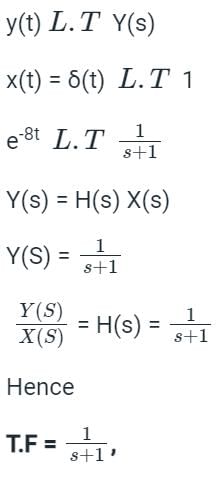
The impulse response is defined as the output of an LTI system due to a unit impulse signal input being applied at time t = 0.
y(t) = h(t) x(t) = h(t) δ(t)
where δ(t) is the unit impulse function and h(t) is the unit impulse response of a continuous-time LTI system.
Calculations:-
Given-
y(t) = e-8t
x(t) = δ(t)
For calculating the transfer function convert the time domain response into Laplace or S domain.

The difference between the output response and the reference signal is known as the _____ signal.- a)actuating
- b)bias
- c)velocity
- d)none of these
Correct answer is option 'A'. Can you explain this answer?
The difference between the output response and the reference signal is known as the _____ signal.
a)
actuating
b)
bias
c)
velocity
d)
none of these

|
Imtiaz Ahmad answered |
Actuating Signal
- The actuating signal is the difference between the output response and the reference signal in a control system.
- It is used to drive the system towards the desired setpoint by adjusting the input signals.
- The actuating signal is crucial for maintaining stability and accuracy in control systems.
- By continuously comparing the output response with the reference signal, the actuating signal ensures that the system stays on track and responds appropriately to any changes or disturbances.
- Overall, the actuating signal plays a key role in ensuring that the control system operates effectively and achieves its desired objectives.
For an electrically heated temperature controlled liquid heater, the best controller is- a)Single–position controller
- b)Two–position controller
- c)Floating controller
- d)Proportional–position controller
Correct answer is option 'C'. Can you explain this answer?
For an electrically heated temperature controlled liquid heater, the best controller is
a)
Single–position controller
b)
Two–position controller
c)
Floating controller
d)
Proportional–position controller

|
Rutuja Pillai answered |
-loop PID controller.
A single-loop PID (Proportional-Integral-Derivative) controller is the best option for an electrically heated temperature controlled liquid heater. This type of controller can accurately regulate the temperature by continuously measuring the temperature and adjusting the heat input based on the error between the setpoint and actual temperature. The proportional term adjusts the heat input in proportion to the error, the integral term adjusts for any steady-state error, and the derivative term helps to anticipate changes in temperature. By using a PID controller, the liquid can be heated to and maintained at the desired temperature with minimal fluctuations.
A single-loop PID (Proportional-Integral-Derivative) controller is the best option for an electrically heated temperature controlled liquid heater. This type of controller can accurately regulate the temperature by continuously measuring the temperature and adjusting the heat input based on the error between the setpoint and actual temperature. The proportional term adjusts the heat input in proportion to the error, the integral term adjusts for any steady-state error, and the derivative term helps to anticipate changes in temperature. By using a PID controller, the liquid can be heated to and maintained at the desired temperature with minimal fluctuations.
Which of the following is not the feature of modern control systems?- a)No oscillation
- b)Quick response
- c)Accuracy
- d)Correct power level
Correct answer is option 'A'. Can you explain this answer?
Which of the following is not the feature of modern control systems?
a)
No oscillation
b)
Quick response
c)
Accuracy
d)
Correct power level
|
|
Mita Mehta answered |
For a good control system the speed of response and stability must be high and for the slow and sluggish response is not used and undesirable.
The Nyquist plot of a open-loop transfer function G(jω)H(jω) of a system encloses the (-1, j0) point. The gain margin of the system is- a)less than zero
- b)greater than zero
- c)zero
- d)infinity
Correct answer is option 'A'. Can you explain this answer?
The Nyquist plot of a open-loop transfer function G(jω)H(jω) of a system encloses the (-1, j0) point. The gain margin of the system is
a)
less than zero
b)
greater than zero
c)
zero
d)
infinity

|
Nilanjan Rane answered |
If Nyquist plot encloses the point (-1, j0), the system is unstable and gain margin is negative.
For the system shown in fig. the number of poles on RHP, LHP, and imaginary axis are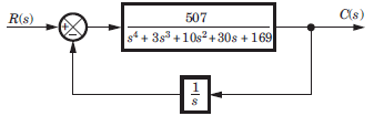
- a)2, 3, 0
- b)3, 2, 0
- c)2, 1, 2
- d)1, 2, 2
Correct answer is option 'D'. Can you explain this answer?
For the system shown in fig. the number of poles on RHP, LHP, and imaginary axis are
a)
2, 3, 0
b)
3, 2, 0
c)
2, 1, 2
d)
1, 2, 2
|
|
Shraddha Yadav answered |
Closed loop transfer function
Routh table is as shown in fig. S.6.2.34

From s4 row down to s0 there is one sign change. So LHP–1 + 1= 2 pole. RHP–1 pole, jw - axis - 2 pole.
The principle of homogeneity and superposition are applied to
- a)Linear time variant systems
- b)Nonlinear time invariant systems
- c)None of these
- d)Linear time invariant systems
Correct answer is option 'D'. Can you explain this answer?
The principle of homogeneity and superposition are applied to
a)
Linear time variant systems
b)
Nonlinear time invariant systems
c)
None of these
d)
Linear time invariant systems
|
|
Sarita Yadav answered |
Superposition theorem states that for two signals additivity and homogeneity property must be satisfied and that is applicable for the LTI systems.
Which among these is a classification of power system stability?- a)Frequency stability
- b)Voltage stability
- c)Rotor angle stability
- d)All of these
Correct answer is option 'D'. Can you explain this answer?
Which among these is a classification of power system stability?
a)
Frequency stability
b)
Voltage stability
c)
Rotor angle stability
d)
All of these
|
|
Tarun Sen answered |
**Classification of Power System Stability**
Power system stability refers to the ability of a power system to maintain a steady, synchronized operation under normal and abnormal conditions. It is crucial for the reliable and efficient operation of the electrical grid. Power system stability can be classified into three main categories:
**1. Frequency Stability:**
Frequency stability refers to the ability of a power system to maintain a stable frequency during normal and abnormal operating conditions. The frequency of an electrical system is determined by the balance between the generation and consumption of electrical power. Any imbalance between generation and load can cause frequency deviations.
**2. Voltage Stability:**
Voltage stability refers to the ability of a power system to maintain a stable voltage profile under normal and abnormal conditions. Voltage fluctuations can lead to equipment malfunctions, damage to electrical devices, and disruption of power supply. Voltage stability is influenced by factors such as load variations, reactive power demand, and system configuration.
**3. Rotor Angle Stability:**
Rotor angle stability, also known as transient stability, refers to the ability of a power system to maintain synchronism and restore stability after a disturbance. It specifically focuses on the stability of the synchronous machines in the power system. Rotor angle stability is critical for maintaining the overall stability of the power system and preventing cascading failures.
**Why the correct answer is option 'D':**
The correct answer is option 'D' - All of these because frequency stability, voltage stability, and rotor angle stability are all different aspects of power system stability. Each aspect addresses a specific characteristic and stability concern of the power system. These three classifications are interrelated and collectively contribute to the overall stability and reliability of the power system.
Frequency stability ensures that the system frequency remains within acceptable limits, preventing excessive speed changes in synchronous generators. Voltage stability ensures that the system voltage remains within acceptable limits, preventing voltage collapse and blackouts. Rotor angle stability ensures that the synchronous generators maintain synchronism and remain stable after disturbances, preventing cascading failures.
Therefore, all three classifications of power system stability - frequency stability, voltage stability, and rotor angle stability - are essential for the reliable operation of the electrical grid and the prevention of power system failures.
In open loop control systems, the control action is independent of the desired________.- a)Error detector
- b)Input signal
- c)Output signal
- d)Actuating signal
Correct answer is option 'C'. Can you explain this answer?
In open loop control systems, the control action is independent of the desired________.
a)
Error detector
b)
Input signal
c)
Output signal
d)
Actuating signal
|
|
Lekha Malhotra answered |
Understanding Open Loop Control Systems
Open loop control systems are characterized by their operational independence from the output. This means that the control action is not influenced by the output signal, which distinguishes them from closed loop systems.
Key Features of Open Loop Control Systems:
- Independence from Output:
- In an open loop system, the control action is determined solely by the input signal and does not adjust based on the output signal's actual performance. This lack of feedback means that the system does not correct itself if the output deviates from the desired result.
- No Error Detection:
- Unlike closed loop systems, open loop systems do not have an error detector to measure the difference between the desired output and the actual output. Thus, they cannot make real-time adjustments.
- Control Action Based on Input:
- The system relies on predetermined inputs to generate a control action. For example, a washing machine set to a specific cycle will operate based on that cycle's parameters without considering the cleanliness of the clothes.
Examples of Open Loop Control Systems:
- Electric Fans:
- A fan operates at a set speed regardless of the room temperature or airflow.
- Toasters:
- A toaster heats bread for a fixed duration, irrespective of the desired toastiness.
Conclusion:
In summary, the correct answer to the question is option 'C'—the control action in open loop systems is indeed independent of the desired output signal. This trait leads to simplicity in design and operation but also limits the system's adaptability and accuracy.
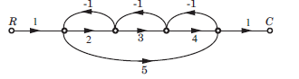
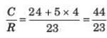
In the signal flow graph shown in fig. the gain C/R is
- a)44/23
- b)29/19
- c)44/19
- d)29/11
Correct answer is option 'A'. Can you explain this answer?
In the signal flow graph shown in fig. the gain C/R is
a)
44/23
b)
29/19
c)
44/19
d)
29/11
|
|
Aim It Academy answered |
P1 = 2 x 3 x 4 = 24 , P2 = 1 x 5 x 1 = 5
L1 = -2, L2 = -3, L3 = -4, L4 = -5,
L1L3 = 8, Δ = 1 -(-2 - 3 - 4 - 5) + 8 = 23, Δ1 = 1, Δ2 = 1 - (-3) = 4,
L1 = -2, L2 = -3, L3 = -4, L4 = -5,
L1L3 = 8, Δ = 1 -(-2 - 3 - 4 - 5) + 8 = 23, Δ1 = 1, Δ2 = 1 - (-3) = 4,
If the roots have negative real parts, then the response is ____________ - a)Stable
- b)Bounded
- c)Unstable
- d)Marginally stable
Correct answer is option 'B'. Can you explain this answer?
If the roots have negative real parts, then the response is ____________
a)
Stable
b)
Bounded
c)
Unstable
d)
Marginally stable
|
|
Starcoders answered |
If the roots have negative real parts, then the response is bounded and eventually decreases to zero.
The phenomena of ‘limit cycles’ and ‘jump resonance’ are observed in- a)linear systems
- b)distributed systems
- c)non-linear systems
- d)discrete time systems
Correct answer is option 'C'. Can you explain this answer?
The phenomena of ‘limit cycles’ and ‘jump resonance’ are observed in
a)
linear systems
b)
distributed systems
c)
non-linear systems
d)
discrete time systems
|
|
Starcoders answered |
Limit Cycles and Jump Resonance in Non-linear Systems
- Limit Cycles in Non-linear Systems:
Limit cycles are periodic orbits in non-linear dynamical systems where the system oscillates within a bounded region indefinitely without either converging towards a fixed point or diverging towards infinity. These cycles are characteristic of non-linear systems and can exhibit a variety of complex behaviors such as chaotic oscillations. - Jump Resonance in Non-linear Systems:
Jump resonance occurs in non-linear systems when the system response suddenly jumps to a different state due to a small change in the input or parameters. This phenomenon is a form of nonlinear resonance where the system's behavior changes abruptly, often leading to unexpected and complex dynamics. Jump resonance can arise in various systems such as mechanical, electrical, or biological systems.
In summary, limit cycles and jump resonance are interesting phenomena observed in non-linear systems, highlighting the rich dynamics and behaviors that can emerge in such systems. These behaviors are distinct from those seen in linear systems and can provide valuable insights into understanding and analyzing complex systems with non-linear dynamics.

Non-minimum phase transfer function is defined as the transfer function
- a)which has zeros and poles only in the left-half s-plane
- b)which has zeroes & poles in the right-half s-plane
- c)Both A & B
- d)None of these
Correct answer is option 'B'. Can you explain this answer?
Non-minimum phase transfer function is defined as the transfer function
a)
which has zeros and poles only in the left-half s-plane
b)
which has zeroes & poles in the right-half s-plane
c)
Both A & B
d)
None of these

|
Tanvi Sarkar answered |
And poles in both the left-half and right-half s-plane
c)which has at least one zero in the right-half s-plane
d)which has at least one pole in the right-half s-plane
The correct answer is d) which has at least one pole in the right-half s-plane. This means that the transfer function has at least one factor in the denominator that is of the form (s - a), where a is a positive real number. Such a factor gives rise to an exponential term e^(at) in the time-domain response, which grows with time instead of decaying. This makes the system non-minimum phase, since it cannot be stabilized by feedback alone.
The Laplace transform of unity function is- a)1
- b) zero
- c) s
- d)1/s
Correct answer is option 'D'. Can you explain this answer?
The Laplace transform of unity function is
a)
1
b)
zero
c)
s
d)
1/s
|
|
Jatin Mukherjee answered |
The laplace transform of unity function i.e.

The type of a system denotes the number of- a)zeros of infinity
- b)poles of origin
- c)poles of infinity
- d)zeros of origin
Correct answer is option 'B'. Can you explain this answer?
The type of a system denotes the number of
a)
zeros of infinity
b)
poles of origin
c)
poles of infinity
d)
zeros of origin

|
Rhea Dasgupta answered |
The type of a system denotes the no. of poles of origin.
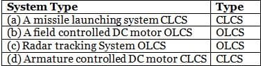
Which of the following is not correctly matched?
(CLCS = Closed Loop Control System and OLCS = Open Loop Control System)
- a)a
- b)b
- c)c
- d)d
Correct answer is option 'C'. Can you explain this answer?
Which of the following is not correctly matched?
(CLCS = Closed Loop Control System and OLCS = Open Loop Control System)
(CLCS = Closed Loop Control System and OLCS = Open Loop Control System)
a)
a
b)
b
c)
c
d)
d
|
|
Imtiaz Ahmad answered |
Radar tracking systems are generally closed-loop systems because they use feedback to continuously adjust and track an object. However, if this refers to the initial detection phase, it might not use feedback, making it an open-loop system. Without additional context, this might be incorrect.
Chapter doubts & questions for Control Systems - RRB JE for Electronics & Communication Engineering 2025 is part of Electronics and Communication Engineering (ECE) exam preparation. The chapters have been prepared according to the Electronics and Communication Engineering (ECE) exam syllabus. The Chapter doubts & questions, notes, tests & MCQs are made for Electronics and Communication Engineering (ECE) 2025 Exam. Find important definitions, questions, notes, meanings, examples, exercises, MCQs and online tests here.
Chapter doubts & questions of Control Systems - RRB JE for Electronics & Communication Engineering in English & Hindi are available as part of Electronics and Communication Engineering (ECE) exam.
Download more important topics, notes, lectures and mock test series for Electronics and Communication Engineering (ECE) Exam by signing up for free.
RRB JE for Electronics & Communication Engineering
3 videos|68 tests
|
|
© EduRev
|
Education Revolution
|


|


Signup to see your scores
go up
within 7 days!
within 7 days!
Takes less than 10 seconds to signup