


All Exams >
Civil Engineering (CE) >
Topicwise Question Bank for Civil Engineering >
All Questions
All questions of Design of Steel Structures for Civil Engineering (CE) Exam


For an I-beam, shape factor is 1.12. The factor of safety in bending is 1.5. if the allowable stress is increased by 20% for wind and earthquake loads, then the load factor is - a)1.10
- b)1.25
- c)1.35
- d)1.40
Correct answer is option 'D'. Can you explain this answer?
For an I-beam, shape factor is 1.12. The factor of safety in bending is 1.5. if the allowable stress is increased by 20% for wind and earthquake loads, then the load factor is
a)
1.10
b)
1.25
c)
1.35
d)
1.40
|
|
Sanvi Kapoor answered |
With increase in allowable stress, the factor of safety will reduce to 1.5/1.2 = 1.25.
∴ Load Factor = FS x shape factor
= 1.25 x 1.12
= 1.40
For reversal of stresses the most suitable bolt is - a)Black bolt
- b)Turned bolt
- c)Friction grip bolt
- d)None of these
Correct answer is option 'C'. Can you explain this answer?
For reversal of stresses the most suitable bolt is
a)
Black bolt
b)
Turned bolt
c)
Friction grip bolt
d)
None of these

|
Sarthak Kulkarni answered |
Friction grip bolt is also called. High strength friction grip bolt or HSFG. The fatigue strength of these bolts is more because of no stress concentrations in the holes which makes it suitable to withstand reversal of stresses.
The maximum longitudinal pitch allowed in bolted joints of tension members is- a)16 times the diameter of the bolt
- b)32 times the diameter of the bolt
- c)16 times the thickness of the plate
- d)32 times the thickness of the plate
Correct answer is option 'C'. Can you explain this answer?
The maximum longitudinal pitch allowed in bolted joints of tension members is
a)
16 times the diameter of the bolt
b)
32 times the diameter of the bolt
c)
16 times the thickness of the plate
d)
32 times the thickness of the plate
|
|
Devansh Banerjee answered |
Maximum longitudinal pitch in bolted joints of tension members
The maximum longitudinal pitch allowed in bolted joints of tension members is an important consideration in the design of steel structures. It is defined as the distance between the centers of adjacent bolts along the direction of the applied load.
Formula
The maximum longitudinal pitch can be calculated using the following formula:
Maximum longitudinal pitch = 16 x t
Where t is the thickness of the plate.
Explanation
The maximum longitudinal pitch is limited to prevent the occurrence of excessive deformation, bending, or buckling of the connected plates. The value of 16 times the thickness of the plate is based on experimental and theoretical studies of bolted connections, and it has been found to provide a safe and reliable limit for most practical situations.
The maximum longitudinal pitch applies to tension members, which are members that are subjected to axial tension forces. These members include bolts, rods, cables, and other structural elements that carry tensile loads.
Conclusion
In conclusion, the maximum longitudinal pitch allowed in bolted joints of tension members is 16 times the thickness of the plate. This value should be used in the design of bolted connections to ensure the structural integrity and safety of steel structures.
What is the ratio of the yield stress in power driven shop rivets relative to the permissible bearing stress of mild steel?- a)1.0
- b)0.8
- c)0.6
- d)0.4
Correct answer is option 'B'. Can you explain this answer?
What is the ratio of the yield stress in power driven shop rivets relative to the permissible bearing stress of mild steel?
a)
1.0
b)
0.8
c)
0.6
d)
0.4
|
|
Anshul Kumar answered |
The yield stress in power drive rivets is 200MPa and bearing stress of mild steel is 250MPa.
Thus, ratio
= 200/250
=0.8
Thus, ratio
= 200/250
=0.8
A steel plate is 300 mm wide and 10 mm thick. A rivet of nominal diameter 18 mm is driven. The net sectional area of the plate is- a)1800 mm2
- b)2805 mm2
- c)2820 mm2
- d)3242 mm2
Correct answer is option 'B'. Can you explain this answer?
A steel plate is 300 mm wide and 10 mm thick. A rivet of nominal diameter 18 mm is driven. The net sectional area of the plate is
a)
1800 mm2
b)
2805 mm2
c)
2820 mm2
d)
3242 mm2

|
Sankar Rane answered |
Net sectional area of the plate is given by,
Anet = (B - nd) x t
= [300-1 x (18 + 1.5)] x 10
= 2805 mm2
Anet = (B - nd) x t
= [300-1 x (18 + 1.5)] x 10
= 2805 mm2
The thickness of lacing bars for single lacing, system should not be less thanwhere l = length between the inner end of connections.- a)l/40
- b)l/50
- c)l/60
- d)l/70
Correct answer is option 'A'. Can you explain this answer?
The thickness of lacing bars for single lacing, system should not be less than
where l = length between the inner end of connections.
a)
l/40
b)
l/50
c)
l/60
d)
l/70
|
|
Swara Gupta answered |
Minimum thickness of lacing bars,
 for single lacing
 for double lacing riveted or welded at intersection.
for single lacing for double lacing riveted or welded at intersection.If 20 mm rivets are used in lacing bars, then the minimum width of lacing bar should be- a)40 mm
- b)60 mm
- c)80 mm
- d)100 mm
Correct answer is option 'B'. Can you explain this answer?
If 20 mm rivets are used in lacing bars, then the minimum width of lacing bar should be
a)
40 mm
b)
60 mm
c)
80 mm
d)
100 mm
|
|
Pallabi Chavan answered |
Minimum width of lacing bar
To determine the minimum width of the lacing bar, we need to consider the size of the rivets used in the lacing bars.
Given:
Size of the rivets used in lacing bars = 20 mm
Explanation:
The minimum width of the lacing bar is determined by the number of rivets that can be accommodated in the width.
To calculate the number of rivets that can be accommodated in the width, we divide the width by the size of the rivets.
Let's consider the options given:
a) 40 mm:
If the lacing bar width is 40 mm, the number of rivets that can be accommodated is 40/20 = 2 rivets.
b) 60 mm:
If the lacing bar width is 60 mm, the number of rivets that can be accommodated is 60/20 = 3 rivets.
c) 80 mm:
If the lacing bar width is 80 mm, the number of rivets that can be accommodated is 80/20 = 4 rivets.
d) 100 mm:
If the lacing bar width is 100 mm, the number of rivets that can be accommodated is 100/20 = 5 rivets.
Conclusion:
From the above calculations, it can be observed that the minimum width of the lacing bar should be 60 mm (Option B) in order to accommodate 3 rivets with a size of 20 mm each.
Consider the following statements for the design of a laced column:
1) In a bolted construction, the minimum width of the lacing bar shall be three times the nominal diameter of the end bolt.
2) The thickness of the flat of a single lacing system shall be not less than one-fortieth of its effective length
3) The angle of inclination of the lacing bar should be less than 40° with the axis of the built-up column
4) The lacing shall be designed for a transverse shear of 2.5% of the axial load on the column
Which of the above statements are correct?
- a)1 only
- b)1 and 3
- c)2 and 4
- d)1, 2 and 4
Correct answer is option 'D'. Can you explain this answer?
Consider the following statements for the design of a laced column:
1) In a bolted construction, the minimum width of the lacing bar shall be three times the nominal diameter of the end bolt.
2) The thickness of the flat of a single lacing system shall be not less than one-fortieth of its effective length
3) The angle of inclination of the lacing bar should be less than 40° with the axis of the built-up column
4) The lacing shall be designed for a transverse shear of 2.5% of the axial load on the column
Which of the above statements are correct?
a)
1 only
b)
1 and 3
c)
2 and 4
d)
1, 2 and 4
|
|
Prerna Menon answered |
Correct Option is D.
For the design of laced columns:
I) The sections to be laced are so spaced that the radius of gyration of the section about the axis perpendicular to the plane of lacing is not less than the radius of gyration about the axis in the plane of lacing.
II) The effective slenderness ratio should be taken as 1.05 times the actual maximum slenderness ratio, in order to account for shear deformation effect.
III) Angle of inclination of the lacing bar should be kept between 40° - 70°. Lacing is most efficient between 35° to 45°, but angle less than 40° would result in a higher length of lacing bar which may then to buckle individually.
IV) The maximum spacing of the lacing bar should be such that the minimum slenderness ratio of the component member should not be greater than 50 or 0.7 times the slenderness ratio of the member.
V) The lacing for compression members should be proportioned to resist transverse shear equal to 2.5% of the axial force in the column.
VI) The minimum flat width should not be less than three times the nominal diameter of the end connector.
VII) The thickness of the lacing flat for a single lacing system should be less than 1/40 of its effective length and for a double lacing system, it should be less than 1/60 of its effective length.
VIII) The slenderness ratio of the lacing bar should be less than 145.
X) The effective length of lacing bar is the length between the inner end rivets/bolts for a single lacing system and 0.7 times this distance for a double lacing system.
Generally the purlins are placed at the panel points so as to avoid- a)axial force in rafter
- b)shear force in rafter
- c)deflection of rafter
- d)bending moment in rafter
Correct answer is option 'D'. Can you explain this answer?
Generally the purlins are placed at the panel points so as to avoid
a)
axial force in rafter
b)
shear force in rafter
c)
deflection of rafter
d)
bending moment in rafter
|
|
Varun Mukherjee answered |
Purlins have a tendency to sag in the direction of sloping roof and sag rods are sometimes provided midway or at third points, between roof trusses, as desirable to take up the sag. These rods reduce the moment MVV and result in a smaller purlin section.
Lacing bars in a steel column should be designed to resist- a)bending moment due to 2.5% of the column load
- b)shear force due to 2.5% of the column load
- c)2.5% of the column load
- d)Both (a) and (b)
Correct answer is option 'B'. Can you explain this answer?
Lacing bars in a steel column should be designed to resist
a)
bending moment due to 2.5% of the column load
b)
shear force due to 2.5% of the column load
c)
2.5% of the column load
d)
Both (a) and (b)
|
|
Shounak Saini answered |
The lacing of compression members should be designed to resist a transverse shear, V = 2.5% of axial force in the member.
For single lacing system on two parallel faces, the force (compressive or tensile) in each bar,

For double lacing system on two parallel planes, the force (compressive or tensile) in each bar,

For single lacing system on two parallel faces, the force (compressive or tensile) in each bar,
For double lacing system on two parallel planes, the force (compressive or tensile) in each bar,
A structural member carrying a pull of 700 kN is connected to a gusset plate using rivets of 20 mm diameter. If the pull required for shearing the rivets, to crush the rivets and to tear the plate per pitch length are 60 kN, 35 kN and 70 kN respectively, then the number of rivets required is
- a)12
- b)18
- c)20
- d)22
Correct answer is option 'C'. Can you explain this answer?
A structural member carrying a pull of 700 kN is connected to a gusset plate using rivets of 20 mm diameter. If the pull required for shearing the rivets, to crush the rivets and to tear the plate per pitch length are 60 kN, 35 kN and 70 kN respectively, then the number of rivets required is
a)
12
b)
18
c)
20
d)
22

|
Constructing Careers answered |
The number of rivers required = force/Rivit value.
Rivit value = min value of shearing, bearing and tearing.
So,
700/35= 20.
Rivit value = min value of shearing, bearing and tearing.
So,
700/35= 20.
The centre to centre maximum distance between bolts in tension member of thickness 10 mm is- a)200 mm
- b)160 mm
- c)120 mm
- d)100 mm
Correct answer is option 'B'. Can you explain this answer?
The centre to centre maximum distance between bolts in tension member of thickness 10 mm is
a)
200 mm
b)
160 mm
c)
120 mm
d)
100 mm
|
|
Maulik Das answered |
The distance between centres of two adjacent rivets, in a line lying in the direction of stress, shaff not exceed 16t or 200 mm, whichever is less in tension members and 12t or 200 mm, whichever is less in compression member
∴ c/c distance = Lesser of (16 x 10, 200)
= 160mm.
∴ c/c distance = Lesser of (16 x 10, 200)
= 160mm.
Minimum pitch of rivets in a riveted joint is- a)2.5 times the dia of rivet hole
- b)2.5 times the dia of rivet
- c)2.5 times the total thickness of the main plate
- d)2.0 times the thickness of thinner plate
Correct answer is option 'B'. Can you explain this answer?
Minimum pitch of rivets in a riveted joint is
a)
2.5 times the dia of rivet hole
b)
2.5 times the dia of rivet
c)
2.5 times the total thickness of the main plate
d)
2.0 times the thickness of thinner plate
|
|
Saptarshi Khanna answered |
Minimum pitch = 2.5 times the nomial dia of rivet.
The plastic hinge formed in a collapse mechanism are 4 and the indeterminacy is 3. The collapse is- a)Partial
- b)Complete
- c)Over complete
- d)Under complete
Correct answer is option 'B'. Can you explain this answer?
The plastic hinge formed in a collapse mechanism are 4 and the indeterminacy is 3. The collapse is
a)
Partial
b)
Complete
c)
Over complete
d)
Under complete
|
|
Navya Kaur answered |
If the number of plastic hinges in the collapse mechanism are less than (r + 1) the collapse is called partial collapse. In such a case, part of the structure may fail making it useless as a whole. If the number of plastic hinges in the collapse mechanism are (r + 1) the collapse is called complete collapse. Such a mechanism has only one degree of freedom. If the number of plastic hinges developed are more than (r + 1), the collapse is called over complete collapse. In such a case there are two or more mechanisms for which the corresponding value of the load is the same, this load value being the actual coljapse load.
If the degree of indeterminacy is r, and the number of plastic hinges developed is N then,
N < (r + 1) Partial collapse
N = r + 1 Complete collapse .
N > r + 1 Overcomplete collapse
If the degree of indeterminacy is r, and the number of plastic hinges developed is N then,
N < (r + 1) Partial collapse
N = r + 1 Complete collapse .
N > r + 1 Overcomplete collapse
The internal pressure coefficient on walls for buildings with large permeability is taken as- a)±0,2
- b)±0.5
- c)±0.7
- d)0
Correct answer is option 'C'. Can you explain this answer?
The internal pressure coefficient on walls for buildings with large permeability is taken as
a)
±0,2
b)
±0.5
c)
±0.7
d)
0
|
|
Sreemoyee Joshi answered |
It includes both interna! as well as external pressure.
In a plate girder, flange angle should be- a)Equal angle section
- b)Unequal angle with long leg horizontal
- c)Unequal angle with short leg horizontal
- d)A bulb angle
Correct answer is option 'B'. Can you explain this answer?
In a plate girder, flange angle should be
a)
Equal angle section
b)
Unequal angle with long leg horizontal
c)
Unequal angle with short leg horizontal
d)
A bulb angle
|
|
Anuj Verma answered |
Unequal flange angles with long horizontal leg; are provided to serve the following purposes:
1. To increase the moment of inertia of the section and
2. A large length is available for making the connection with the flange plate.
1. To increase the moment of inertia of the section and
2. A large length is available for making the connection with the flange plate.
The ratio of yield stress in tension to compression in mild steel is- a)Less than 1
- b)Greater than 1
- c)Equal to 1
- d)None of these
Correct answer is option 'B'. Can you explain this answer?
The ratio of yield stress in tension to compression in mild steel is
a)
Less than 1
b)
Greater than 1
c)
Equal to 1
d)
None of these
|
|
Jay Menon answered |
Ratio of Yield Stress in Tension to Compression in Mild Steel
Yield stress is the stress at which a material begins to deform plastically. In mild steel, the yield stress in tension and compression is not the same. The ratio of yield stress in tension to compression in mild steel is given by:
σyt/σyc > 1
where σyt is the yield stress in tension and σyc is the yield stress in compression.
Explanation:
Mild steel is a ductile material that can undergo large plastic deformations before failure. The yield stress in tension is greater than the yield stress in compression because the material is weaker in compression due to buckling and instability.
When a mild steel specimen is subjected to tension, it elongates and necks down until it reaches the yield point. At this point, the material begins to deform plastically and the stress required to cause further deformation decreases. In compression, however, the material is more prone to buckling and instability, which can cause premature failure.
Therefore, the yield stress in compression is lower than the yield stress in tension, resulting in a ratio greater than 1.
Conclusion:
The ratio of yield stress in tension to compression in mild steel is greater than 1. This is because mild steel is weaker in compression due to buckling and instability.
A 6 mm thick mild steel plate is connected to an 8 mm thick plate by 16 mm diameter shop rivets. What is-the number of rivets required to carry an 80 kN load?- a)2
- b)3
- c)4
- d)6
Correct answer is option 'C'. Can you explain this answer?
A 6 mm thick mild steel plate is connected to an 8 mm thick plate by 16 mm diameter shop rivets. What is-the number of rivets required to carry an 80 kN load?
a)
2
b)
3
c)
4
d)
6
|
|
Poulomi Khanna answered |
For shop rivets permissible stresses are, In shearing, τs = 100 MPa
In bearing, σb = 300 MPa
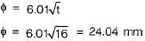
The gross diameter of hole (D)
.= 16 + 1.5 = 17.5 mm
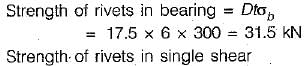
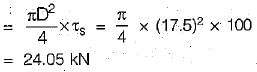
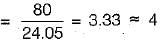
∴ Rivet value = 24.05 kN
Hence, number of rivets required
In bearing, σb = 300 MPa
The gross diameter of hole (D)
.= 16 + 1.5 = 17.5 mm
∴ Rivet value = 24.05 kN
Hence, number of rivets required
According to IS Specifications, the maximum pitch of rivets in compression is
(where t is thickness of thinnest outside plate or angle)
- a)lesser of 200 mm and 12 t
- b)lesser of 200 mm and 16 t
- c)lesser of 300 mm and 32 t
- d)lesser of 300 mm and 24 t
Correct answer is option 'A'. Can you explain this answer?
According to IS Specifications, the maximum pitch of rivets in compression is
(where t is thickness of thinnest outside plate or angle)
a)
lesser of 200 mm and 12 t
b)
lesser of 200 mm and 16 t
c)
lesser of 300 mm and 32 t
d)
lesser of 300 mm and 24 t
|
|
Hiral Sharma answered |
Maximum pitch of rivets in compression = 12t or 200 mm whichever is less
When load line coincides with the C.G. of rivet group, then the rivets are subjected to- a)Shear only
- b)Tension only
- c)Bending only
- d)Both shear and bending
Correct answer is option 'A'. Can you explain this answer?
When load line coincides with the C.G. of rivet group, then the rivets are subjected to
a)
Shear only
b)
Tension only
c)
Bending only
d)
Both shear and bending
|
|
Alok Iyer answered |
Explanation:
Load line coinciding with the C.G. of rivet group:
When the load line coincides with the center of gravity (C.G.) of the rivet group, it means that the load applied is passing through the center of gravity of the rivet group.
Rivets subjected to shear only:
- In this case, the load is directly acting on the C.G. of the rivet group, resulting in shear forces being applied to the rivets.
- Shear forces are forces that act parallel to the plane of the material, causing internal sliding or deformation of the material along the plane.
Therefore, when the load line coincides with the C.G. of the rivet group, the rivets are subjected to shear forces only. This is because the load is directly causing shear stresses within the rivet group, without inducing any tensile or bending stresses.
The difference between gross diameter and nominal diameter for the rivets up to 25 mm diameter is- a)1.0 mm
- b)1.5 mm
- c)2.0 mm
- d)2.5 mm
Correct answer is option 'B'. Can you explain this answer?
The difference between gross diameter and nominal diameter for the rivets up to 25 mm diameter is
a)
1.0 mm
b)
1.5 mm
c)
2.0 mm
d)
2.5 mm
|
|
Bhargavi Sengupta answered |
Gross diameter
= Nominal diameter + 1.5 mm, φ≤ 25 mm
Gross diameter
= Nominal diameter + 2 mm, φ > 25 mm φ = Nominal diameter
= Nominal diameter + 1.5 mm, φ≤ 25 mm
Gross diameter
= Nominal diameter + 2 mm, φ > 25 mm φ = Nominal diameter
Tacking rivets in tension members, are provided at a pitch in line not exceeding- a)25 cm
- b)50 cm
- c)60 cm
- d)100 cm
Correct answer is option 'D'. Can you explain this answer?
Tacking rivets in tension members, are provided at a pitch in line not exceeding
a)
25 cm
b)
50 cm
c)
60 cm
d)
100 cm

|
Raksha Nair answered |
Tacking rivets in tension members refers to the process of placing rivets at regular intervals along the length of a structural member to improve its resistance to tension forces. The pitch, or spacing, of these rivets is an important consideration as it affects the overall strength and stability of the member.
The correct answer to this question is option 'D', which states that the pitch should not exceed 100 cm. Let's understand why this is the correct answer.
- Importance of Rivet Pitch: The pitch of rivets in tension members is crucial because it determines the spacing between rivets, which in turn affects the distribution of forces and stresses within the member. If the pitch is too large, the member may experience excessive deformation or failure under tension loads. On the other hand, if the pitch is too small, it may result in unnecessary material and labor costs.
- Rivet Efficiency: Rivets are typically used to connect two or more steel plates together, creating a joint that can transfer loads between the plates. The efficiency of the rivet joint depends on the strength and stiffness of the rivets as well as the spacing between them. By providing a suitable pitch, the rivets can effectively distribute the tension load across the entire member, minimizing stress concentrations.
- Maximum Pitch Limit: The given options suggest various pitch values ranging from 25 cm to 100 cm. Among these options, the maximum pitch limit of 100 cm is considered appropriate for tacking rivets in tension members. This means that the spacing between individual rivets should not exceed 100 cm.
- Design Considerations: The specific value of the maximum pitch limit may vary depending on factors such as the material properties, member dimensions, and design requirements. However, for typical structural steel members, a pitch of 100 cm is commonly used. This spacing ensures that the rivets are adequately distributed along the length of the member, providing sufficient strength and stability.
In conclusion, when tacking rivets in tension members, it is important to provide a suitable pitch to ensure the structural integrity of the member. The maximum pitch limit should not exceed 100 cm, as this spacing allows for effective load distribution and minimizes the risk of failure under tension loads.
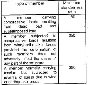
A tension member, if subjected to possible reversal of stress due to wind or earthquake the slenderness ratio of the member should not exceed- a)180
- b)300
- c)250
- d)350
Correct answer is option 'D'. Can you explain this answer?
A tension member, if subjected to possible reversal of stress due to wind or earthquake the slenderness ratio of the member should not exceed
a)
180
b)
300
c)
250
d)
350

|
Sandeep Sen answered |
Slenderness Ratio for Tension Members
A tension member in a structure is a component that is designed to resist axial tensile forces. Examples of tension members include cables, rods, and tie-rods. When designing a tension member, one of the important considerations is its slenderness ratio.
Definition of Slenderness Ratio
Slenderness ratio is defined as the ratio of the effective length of a member to its least radius of gyration. It is a measure of the member's ability to resist buckling under axial compression. For a tension member, the slenderness ratio is still an important factor to consider, especially if there is a possibility of reversal of stress due to wind or earthquake.
Limitation of Slenderness Ratio for Tension Members
The maximum slenderness ratio for a tension member is limited to prevent buckling under axial compression. However, when a tension member is subjected to possible reversal of stress due to wind or earthquake, the slenderness ratio should not exceed a certain limit. According to the Indian Standard Code of Practice for Structural Steel, the maximum slenderness ratio for tension members subjected to possible reversal of stress is 350.
Conclusion
In conclusion, when designing a tension member in a structure, it is important to consider its slenderness ratio. For tension members that may be subjected to reversal of stress due to wind or earthquake, the maximum slenderness ratio should not exceed 350, according to the Indian Standard Code of Practice for Structural Steel.
What is the number of plastic hinges formed if an indeterminate beam with redundancy R is to become determinate?- a)R - 1
- b)R
- c)R + 1
- d)R + 2
Correct answer is option 'B'. Can you explain this answer?
What is the number of plastic hinges formed if an indeterminate beam with redundancy R is to become determinate?
a)
R - 1
b)
R
c)
R + 1
d)
R + 2
|
|
Lakshmi Datta answered |
The number of plastic hinges required to make an indeterminate beam determinate is R where R is the degree of redundancy. However, for the complete collapse of the beam (R + 1) plastic hinges will be required.
The maximum permissible span of asbestos cement sheets is- a)650 mm
- b)810 mm
- c)1250 mm
- d)1680 mm
Correct answer is option 'D'. Can you explain this answer?
The maximum permissible span of asbestos cement sheets is
a)
650 mm
b)
810 mm
c)
1250 mm
d)
1680 mm
|
|
Arnab Saini answered |
Asbestos Cement Sheets
Asbestos cement sheets are commonly used as roofing and cladding material in industrial and agricultural buildings. These sheets are made by mixing asbestos fibers and cement together, which gives them strength, durability, and resistance to fire, weather, and insects.
Maximum Permissible Span
The maximum permissible span of asbestos cement sheets is the distance between two supports that the sheet can span without sagging or breaking. This span depends on various factors like the thickness and quality of the sheet, the load it will bear, the wind and snow load in the area, and the temperature and humidity conditions.
The maximum permissible span of asbestos cement sheets is calculated based on the deflection limit of L/180, where L is the span of the sheet. This means that the sheet should not deflect more than 1/180th of its length, which ensures that it remains stable and does not crack or break.
Answer
The maximum permissible span of asbestos cement sheets is 1680 mm or 1.68 meters. This means that any distance between two supports greater than 1.68 meters will cause the sheet to sag or break, which can be dangerous and expensive to repair. Therefore, it is important to choose the right thickness and quality of the sheet and install it properly with adequate supports and fasteners to ensure its safety and longevity.
IS 800 : 2007 is based on- a)Elastic design method
- b)Ultimate load method
- c)Working stress method
- d)Limit state method
Correct answer is option 'D'. Can you explain this answer?
IS 800 : 2007 is based on
a)
Elastic design method
b)
Ultimate load method
c)
Working stress method
d)
Limit state method
|
|
Subham Unni answered |
New code of steel structures, IS : 800, has been formatted by considering limit state design method while earlier one was based on working stress method.
A single angle is connected by one leg only. If the area of outstanding leg is x, net area of connecting leg is y, and k is reduction factor whose value is less than 1, then the net effective area of angle in tension will be:- a)x + y
- b)x + ky
- c)y + kx
- d)k(x + y)
Correct answer is option 'C'. Can you explain this answer?
A single angle is connected by one leg only. If the area of outstanding leg is x, net area of connecting leg is y, and k is reduction factor whose value is less than 1, then the net effective area of angle in tension will be:
a)
x + y
b)
x + ky
c)
y + kx
d)
k(x + y)
|
|
Tanvi Shah answered |
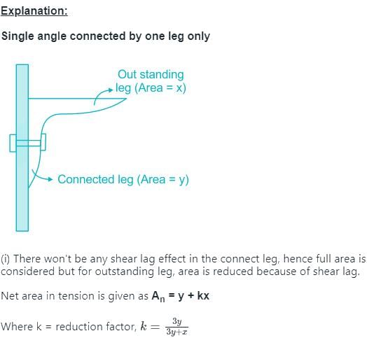
Correct answer is C.
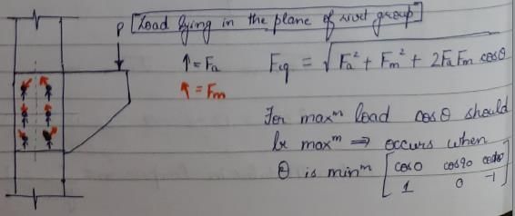
When the axis of load lies in the plane of rivet group, then the most heavily loaded rivet will be the one which.where, Fa is the load shared by each rivet due to axial load and Fm is the shearing load due to moment in any rivet- a)is at the CG of the rivet group
- b)is at the minimum distance from CG of the rivet group
- c)gives the maximum angle between the two forces Fa and Fm
- d)gives the minimum angle between the two forces Fa and Fm
Correct answer is option 'D'. Can you explain this answer?
When the axis of load lies in the plane of rivet group, then the most heavily loaded rivet will be the one which.
where, Fa is the load shared by each rivet due to axial load and Fm is the shearing load due to moment in any rivet
a)
is at the CG of the rivet group
b)
is at the minimum distance from CG of the rivet group
c)
gives the maximum angle between the two forces Fa and Fm
d)
gives the minimum angle between the two forces Fa and Fm
|
|
Pallabi Kulkarni answered |
If the same number of rivets has been used in the joints then which of the following pattern will yield highest efficiency- a)Chain
- b)Staggered
- c)Diamond
- d)All of the above yield same efficiency
Correct answer is option 'C'. Can you explain this answer?
If the same number of rivets has been used in the joints then which of the following pattern will yield highest efficiency
a)
Chain
b)
Staggered
c)
Diamond
d)
All of the above yield same efficiency
|
|
Jaideep Malik answered |
The width of the main plate required is less in case diamond riveting. The critical section is diamond riveting passes through one or two rivet holes. The width of the plate required to accommodate diamond pattern is less than that for chain pattern by d(n - 1).
n = Number of rivets in chain riveting at critical section
d = Gross diameter of rivets
n = Number of rivets in chain riveting at critical section
d = Gross diameter of rivets
The effect of axial force and shear force on the plastic moment capacity of a section are - a)to decrease and to increase the plastic moment respectively
- b)to increase and to decrease the plastic moment respectively
- c)to increase the plastic moment capacity in both cases
- d)to decrease the plastic moment capacity in both cases
Correct answer is option 'D'. Can you explain this answer?
The effect of axial force and shear force on the plastic moment capacity of a section are
a)
to decrease and to increase the plastic moment respectively
b)
to increase and to decrease the plastic moment respectively
c)
to increase the plastic moment capacity in both cases
d)
to decrease the plastic moment capacity in both cases
|
|
Gitanjali Chauhan answered |
Effect of Axial Force and Shear Force on Plastic Moment Capacity
Axial force and shear force are two important factors that affect the plastic moment capacity of a section. Let us see how these forces affect the plastic moment capacity.
Effect of Axial Force on Plastic Moment Capacity
Axial force is the force that is applied along the longitudinal axis of the member. When an axial force is applied to a member, it induces additional stresses in the member which can reduce the plastic moment capacity of the section. The effect of axial force on the plastic moment capacity of a section is as follows:
- When the axial force is compressive, it reduces the plastic moment capacity of the section. This is because the compressive force increases the stress in the compression side of the section, which can lead to premature yielding and reduce the plastic moment capacity.
- When the axial force is tensile, it does not affect the plastic moment capacity of the section.
Effect of Shear Force on Plastic Moment Capacity
Shear force is the force that is applied perpendicular to the longitudinal axis of the member. When a shear force is applied to a member, it induces additional stresses in the member which can increase or decrease the plastic moment capacity of the section. The effect of shear force on the plastic moment capacity of a section is as follows:
- When the shear force is applied in the same direction as the plastic moment, it increases the plastic moment capacity of the section. This is because the shear force induces a shear stress in the section which adds to the bending stress and increases the plastic moment capacity.
- When the shear force is applied in the opposite direction as the plastic moment, it reduces the plastic moment capacity of the section. This is because the shear force induces a shear stress in the section which subtracts from the bending stress and reduces the plastic moment capacity.
Conclusion
In conclusion, axial force and shear force are two important factors that affect the plastic moment capacity of a section. Axial force reduces the plastic moment capacity of the section when it is compressive, while shear force increases the plastic moment capacity when it is applied in the same direction as the plastic moment and reduces it when it is applied in the opposite direction. Therefore, both axial force and shear force reduce the plastic moment capacity of a section.
Which one of the following stresses is independent of yield stress as a permissible stress for steel members?- a)Axial tensile stress
- b)Maximum shear stress
- c)Bearing stress
- d)Stress in slab base
Correct answer is option 'D'. Can you explain this answer?
Which one of the following stresses is independent of yield stress as a permissible stress for steel members?
a)
Axial tensile stress
b)
Maximum shear stress
c)
Bearing stress
d)
Stress in slab base
|
|
Neha Mukherjee answered |
Permissible values
Axial tensile stress = 0.6fy
Bearing stress = 0.75fy
Maximum shear stress = 0.45fy
Stress in slab base = 185 MPa for all type of steels.
Axial tensile stress = 0.6fy
Bearing stress = 0.75fy
Maximum shear stress = 0.45fy
Stress in slab base = 185 MPa for all type of steels.
Minimum spacing of vertical stiffeners is limited to
where d is the distance between flange angles.- a)D/4
- b)D/3
- c)D/2
- d)2D/3
Correct answer is option 'B'. Can you explain this answer?
Minimum spacing of vertical stiffeners is limited to
where d is the distance between flange angles.
where d is the distance between flange angles.
a)
D/4
b)
D/3
c)
D/2
d)
2D/3
|
|
Anmol Roy answered |
Vertical stiffeners are provided at the spacing of 0.33 of to 1.5 d where d is the distance between the flanges ignoring fillets and if horizontal stiffeners are also provided d is the maximum clear depth of the web. Spacing can be reduced near the supports where the shear force is large compared to the centre of the girder.
For a compression member having the same effective length about any cross-sectional axis, the most preferred section from the point of view of strength is- a)A box
- b)An I-section
- c)A circular tube
- d)A single angle
Correct answer is option 'A'. Can you explain this answer?
For a compression member having the same effective length about any cross-sectional axis, the most preferred section from the point of view of strength is
a)
A box
b)
An I-section
c)
A circular tube
d)
A single angle
|
|
Gitanjali Menon answered |
Slenderness ratio, 
Lesser the value of λ (greater radius of gyration r), the column can take more load. Maximum radius of gyration is obtained when material is farthest from centroid. Therefore box section is best.
Lesser the value of λ (greater radius of gyration r), the column can take more load. Maximum radius of gyration is obtained when material is farthest from centroid. Therefore box section is best.
In case of single angles in tension connected by one leg only, the net effective area as per IS : 800 is
Where a is net sectional area of connected leg and b is area of the outstanding leg.- a)gross area-area of holes
- b)

- c)

- d)

Correct answer is option 'B'. Can you explain this answer?
In case of single angles in tension connected by one leg only, the net effective area as per IS : 800 is
Where a is net sectional area of connected leg and b is area of the outstanding leg.
Where a is net sectional area of connected leg and b is area of the outstanding leg.
a)
gross area-area of holes
b)
c)
d)
|
|
Madhurima Banerjee answered |

Failure of tension member is considered when either of following statement is true
1. Excessive elongation in member.
2. Rupture of critical section.
3. Buckling of member.
4. Shear block failure of end connection.- a)1, 2 and 3
- b)2, 3 and 4
- c)1, 3 and 4
- d)1, 2 and 4
Correct answer is option 'D'. Can you explain this answer?
Failure of tension member is considered when either of following statement is true
1. Excessive elongation in member.
2. Rupture of critical section.
3. Buckling of member.
4. Shear block failure of end connection.
1. Excessive elongation in member.
2. Rupture of critical section.
3. Buckling of member.
4. Shear block failure of end connection.
a)
1, 2 and 3
b)
2, 3 and 4
c)
1, 3 and 4
d)
1, 2 and 4
|
|
Sakshi Basak answered |
The three criterion for failure has been considered in new code. Buckling takes place in compression members and not in tension members.
20 mm diameter rivets are used to connect 10 mm thick piates. The permlssitcle stresses for rivets in shear and bearing are 80 MPa and 250 MPa respectively. The difference of rivet value in single shear and double shear is - a)27.6 kN
- b)24.7 kN
- c)32.5 kN
- d)34.2 kN
Correct answer is option 'B'. Can you explain this answer?
20 mm diameter rivets are used to connect 10 mm thick piates. The permlssitcle stresses for rivets in shear and bearing are 80 MPa and 250 MPa respectively. The difference of rivet value in single shear and double shear is
a)
27.6 kN
b)
24.7 kN
c)
32.5 kN
d)
34.2 kN
|
|
Rajat Sen answered |
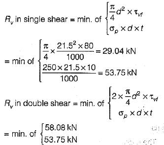
Difference = 53.75 - 29.04 = 24.7 kN
If the thickness of plate to be connected by a rivet is 16 mm, then suitable size of rivet as per Unwin’s formula will be- a)16 mm
- b)20 mm
- c)24 mm
- d)27 mm
Correct answer is option 'C'. Can you explain this answer?
If the thickness of plate to be connected by a rivet is 16 mm, then suitable size of rivet as per Unwin’s formula will be
a)
16 mm
b)
20 mm
c)
24 mm
d)
27 mm
|
|
Sankar Dasgupta answered |
According to Unwin’s formula nominal diameter of rivet is given by,
A simply supported beam of uniform cross-section has span L and is loaded by a point load P at its mid-span. What is the length of the elastoplastic zone of the plastic hinge?- a)L/3
- b)2L/3
- c)L/2
- d)3L/4
Correct answer is option 'A'. Can you explain this answer?
A simply supported beam of uniform cross-section has span L and is loaded by a point load P at its mid-span. What is the length of the elastoplastic zone of the plastic hinge?
a)
L/3
b)
2L/3
c)
L/2
d)
3L/4
|
|
Abhay Banerjee answered |
Question Analysis:
A simply supported beam of uniform cross-section has span L and is loaded by a point load P at its mid-span. We need to find the length of the elastoplastic zone of the plastic hinge.
Given:
Span of the beam = L
Point Load = P at mid-span
To find:
Length of the elastoplastic zone of the plastic hinge
Solution:
The plastic hinge is the region of the beam that has experienced plastic deformation. The length of the elastoplastic zone of the plastic hinge is the distance from the point of the load application to the end of the plastic hinge.
Let us consider the beam as shown below:
The mid-span of the beam is the point of application of the load P. Let the length of the plastic hinge be 'x'. The beam will experience plastic deformation in the region between A and B.
We can calculate the length of the plastic hinge using the following steps:
Step 1: Calculate the maximum moment in the beam
The maximum moment in the beam occurs at mid-span and is given by:
Mmax = PL/4
Step 2: Calculate the plastic moment capacity of the beam
The plastic moment capacity of the beam is given by:
Mp = Zfy/1.5
where Z is the plastic section modulus, fy is the yield strength of the material.
Step 3: Calculate the length of the plastic hinge
The length of the plastic hinge is given by:
x = Mp/Mmax
Substituting the values of Mp and Mmax, we get:
x = (Zfy/1.5)/(PL/4)
x = 2Zfy/(3PL)
Since the beam has uniform cross-section, the plastic section modulus Z is proportional to the cube of the depth of the beam. Therefore, we can write:
Z = kd^3
where k is a constant and d is the depth of the beam.
Substituting the value of Z in the equation for x, we get:
x = 2kd^3fy/(3PL)
Since the beam is simply supported, the maximum moment occurs at mid-span. Therefore, the depth of the beam at mid-span is given by:
d = (PL^3)/(48EI)
where E is the modulus of elasticity of the material.
Substituting the value of d in the equation for x, we get:
x = kfyL^2/(18EI)
x = L/3
Therefore, the length of the elastoplastic zone of the plastic hinge is L/3.
Answer: Option A (L/3)
Consider the following statements:
A grillage base is checked for
1. bending
2. shear
3. compression
4. web crippling Which of these statements are correct?- a)1 and 4
- b)1 and 3
- c)2, 3 and 4
- d)1,2 and 4
Correct answer is option 'D'. Can you explain this answer?
Consider the following statements:
A grillage base is checked for
1. bending
2. shear
3. compression
4. web crippling
A grillage base is checked for
1. bending
2. shear
3. compression
4. web crippling
Which of these statements are correct?
a)
1 and 4
b)
1 and 3
c)
2, 3 and 4
d)
1,2 and 4
|
|
Arshiya Roy answered |
The grillage base essentially consists of steel beams encased in concrete. They are provided when,
(i) The load on the column is very heavy.
(ii) The bearing capacity of the soil on which the concrete block is to be placed may be poor.
They are designed for bending, shear and web crippling.
(i) The load on the column is very heavy.
(ii) The bearing capacity of the soil on which the concrete block is to be placed may be poor.
They are designed for bending, shear and web crippling.
Which one of the following is correct?
An intermediate vertical stiffener connected to the web is designed to withstand a shearing force of not less than
where t is web thickness in mm and h is the outstand of stiffener in mm.- a)100t/h
- b)150t2/h
- c)125h/t2
- d)125t2/h
Correct answer is option 'D'. Can you explain this answer?
Which one of the following is correct?
An intermediate vertical stiffener connected to the web is designed to withstand a shearing force of not less than
where t is web thickness in mm and h is the outstand of stiffener in mm.
An intermediate vertical stiffener connected to the web is designed to withstand a shearing force of not less than
where t is web thickness in mm and h is the outstand of stiffener in mm.
a)
100t/h
b)
150t2/h
c)
125h/t2
d)
125t2/h
|
|
Nishanth Banerjee answered |
As per clause 6.7.4.6 of IS: 800-1984, intermediate horizontal stiffeners not subjected to external loads shall be connected to web by rivets or welds, so as to withstand a shearing force, between each component of the stiffener and the web of not less than,
125t2/h kN/m
125t2/h kN/m
Consider the following statements:
Lug angles are used to
1. increase the lengths of the end connections of angle section.
2. decrease the lengths of the end connections of angle section.
3. increase the lengths of the end connections of channel section.
4. decrease the lengths of the end connections of channel section.Which of these statements are correct?- a)1 and 2
- b)2 and 4
- c)1,3 and 4
- d)1, 2 and 3
Correct answer is option 'B'. Can you explain this answer?
Consider the following statements:
Lug angles are used to
1. increase the lengths of the end connections of angle section.
2. decrease the lengths of the end connections of angle section.
3. increase the lengths of the end connections of channel section.
4. decrease the lengths of the end connections of channel section.
Lug angles are used to
1. increase the lengths of the end connections of angle section.
2. decrease the lengths of the end connections of angle section.
3. increase the lengths of the end connections of channel section.
4. decrease the lengths of the end connections of channel section.
Which of these statements are correct?
a)
1 and 2
b)
2 and 4
c)
1,3 and 4
d)
1, 2 and 3
|
|
Shilpa Pillai answered |
Lug angles are sometimes used to reduce the length of the connections. However their main purpose is to accommodate more number of rivets so that size of the gusset plate may be reduced.
Tacking rivets in compression plates not exposed to the weather, have a pitch not exceeding 300 mm or- a)16 times the thickness of outside plate
- b)24 times the thickness of outside plate
- c)32 times the thickness of outside plate
- d)36 times the thickness of outside plate
Correct answer is option 'C'. Can you explain this answer?
Tacking rivets in compression plates not exposed to the weather, have a pitch not exceeding 300 mm or
a)
16 times the thickness of outside plate
b)
24 times the thickness of outside plate
c)
32 times the thickness of outside plate
d)
36 times the thickness of outside plate
|
|
Raghav Mukherjee answered |
Tacking Rivets in Compression Plates
When tacking rivets in compression plates that are not exposed to the weather, there are certain guidelines to follow to ensure structural integrity. One of the guidelines is the pitch of the rivets.
Pitch of Rivets
The pitch of the rivets refers to the distance between each rivet. This distance is important because it affects the strength and stability of the structure. The pitch of the rivets should not exceed 300 mm or 32 times the thickness of the outside plate.
Formula
The formula for determining the maximum pitch of rivets in compression plates is as follows:
Pitch ≤ 300 mm or 32 × t
Where:
t = thickness of the outside plate
Explanation of Options
a) 16 times the thickness of outside plate - This option is not correct because the pitch of the rivets should not be less than 300 mm or 32 times the thickness of the outside plate.
b) 24 times the thickness of outside plate - This option is not correct because the pitch of the rivets should not be less than 300 mm or 32 times the thickness of the outside plate.
c) 32 times the thickness of outside plate - This option is correct because the maximum pitch of rivets in compression plates should not exceed 300 mm or 32 times the thickness of the outside plate.
d) 36 times the thickness of outside plate - This option is not correct because the pitch of the rivets should not exceed 300 mm or 32 times the thickness of the outside plate.
Conclusion
The maximum pitch of rivets in compression plates that are not exposed to the weather should not exceed 300 mm or 32 times the thickness of the outside plate. This is important to ensure structural integrity and stability.
A plate used for connecting two or more structural members intersecting each other is termed as- a)Template
- b)Baseplate
- c)Gusset plate
- d)Shoe plate
Correct answer is option 'C'. Can you explain this answer?
A plate used for connecting two or more structural members intersecting each other is termed as
a)
Template
b)
Baseplate
c)
Gusset plate
d)
Shoe plate
|
|
Samridhi Choudhary answered |
Base plates are provided to distribute the load of a column on greater area.
In a simply supported beam of span l, each end is restrained against torsion, compression flange being unrestrained. According to IS : 800, the effective length of the compression flange will be equal to- a)l
- b)0.85l
- c)0.75l
- d)0.70l
Correct answer is option 'A'. Can you explain this answer?
In a simply supported beam of span l, each end is restrained against torsion, compression flange being unrestrained. According to IS : 800, the effective length of the compression flange will be equal to
a)
l
b)
0.85l
c)
0.75l
d)
0.70l
|
|
Rajeev Menon answered |
a) l. According to IS:800 (Indian Standard: Code of Practice for General Construction in Steel), the effective length of the compression flange of a simply supported beam of span l, with each end restrained against torsion and the compression flange unrestrained, is equal to l. The effective length of the compression flange is used to calculate the design moment of the beam and the size of the compression flange required to resist the applied loads. The effective length is based on the assumption that the compression flange is able to develop its full strength and that the beam is able to resist the applied loads without buckling. The effective length may be adjusted based on the specific conditions of the beam and the applied loads.
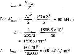
A cantilever steel beam of 3 m span carries a uniformly distributed load of 20 kN/m inclusive of self-weight. The beam comprises of ISLB200@198 N/m, flange = 100 mm x 7.3 mm; web thickness = 5.4 mm; Ixx= 1696.6 cm4; Iyy = 115.4 cm4. What is the maximum bending stress in the beam ?- a)132.62 N/mm2
- b)530.47 N/mm2
- c)1949.74 N/mm2
- d)3899.48 N/mm2
Correct answer is option 'B'. Can you explain this answer?
A cantilever steel beam of 3 m span carries a uniformly distributed load of 20 kN/m inclusive of self-weight. The beam comprises of ISLB200@198 N/m, flange = 100 mm x 7.3 mm; web thickness = 5.4 mm; Ixx= 1696.6 cm4; Iyy = 115.4 cm4. What is the maximum bending stress in the beam ?
a)
132.62 N/mm2
b)
530.47 N/mm2
c)
1949.74 N/mm2
d)
3899.48 N/mm2
|
|
Prashanth Mehra answered |
The maximum bending stress is given by,
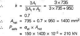
The capacity of a single ISA 100 x 100 x 10 mm as tension member connected by one leg only using 6 rivets of 20 mm diameter isThe allowable stress is 150 N/mm2- a)333 kN
- b)253 kN
- c)238 kN
- d)210 kN
Correct answer is option 'D'. Can you explain this answer?
The capacity of a single ISA 100 x 100 x 10 mm as tension member connected by one leg only using 6 rivets of 20 mm diameter is
The allowable stress is 150 N/mm2
a)
333 kN
b)
253 kN
c)
238 kN
d)
210 kN
|
|
Rounak Mehta answered |
The net area of the tension member is given by,
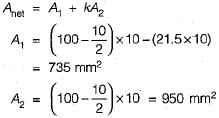
The angle section is connected by one leg only.
The angle section is connected by one leg only.
The mechanism method and the statical methods give- a)lower and upper bounds respectively on the strength of structure
- b)upper and lower bounds respectively on the strength of structure
- c)lower bound on the strength of structure
- d)upper bound on the strength of structure
Correct answer is option 'B'. Can you explain this answer?
The mechanism method and the statical methods give
a)
lower and upper bounds respectively on the strength of structure
b)
upper and lower bounds respectively on the strength of structure
c)
lower bound on the strength of structure
d)
upper bound on the strength of structure
|
|
Ameya Sen answered |
The static method represents the lower limit to the true ultimate load and has a maximum factor of safety.
Purlins are provided, in industrial buildings, over roof trusses to carry dead loads, live loads and wind loads. As per IS code, what are they assumed to be?- a)Simply supported
- b)Cantilever
- c)Continuous
- d)Fixed
Correct answer is option 'C'. Can you explain this answer?
Purlins are provided, in industrial buildings, over roof trusses to carry dead loads, live loads and wind loads. As per IS code, what are they assumed to be?
a)
Simply supported
b)
Cantilever
c)
Continuous
d)
Fixed
|
|
Aashna Chakraborty answered |
Purlins are assumed to be continuous beams.
Chapter doubts & questions for Design of Steel Structures - Topicwise Question Bank for Civil Engineering 2025 is part of Civil Engineering (CE) exam preparation. The chapters have been prepared according to the Civil Engineering (CE) exam syllabus. The Chapter doubts & questions, notes, tests & MCQs are made for Civil Engineering (CE) 2025 Exam. Find important definitions, questions, notes, meanings, examples, exercises, MCQs and online tests here.
Chapter doubts & questions of Design of Steel Structures - Topicwise Question Bank for Civil Engineering in English & Hindi are available as part of Civil Engineering (CE) exam.
Download more important topics, notes, lectures and mock test series for Civil Engineering (CE) Exam by signing up for free.
|
© EduRev
|
Education Revolution
|


|


Signup to see your scores
go up within 7 days!
Access 1000+ FREE Docs, Videos and Tests
Takes less than 10 seconds to signup