


All questions of Paper-II (ESE Electrical) for Electrical Engineering (EE) Exam
Which fault is more frequently occurring in power system?- a)Line to line fault
- b)Double line to ground fault
- c)Single line to ground fault
- d)Symmetrical 3 phase fault
Correct answer is option 'C'. Can you explain this answer?
Which fault is more frequently occurring in power system?
a)
Line to line fault
b)
Double line to ground fault
c)
Single line to ground fault
d)
Symmetrical 3 phase fault
|
|
Anjana Singh answered |
The different type of faults in power systems are:
- Single line to ground fault (LG)
- Line to line fault (LL)
- Double line to ground fault (LLG)
- Three-phase faults (LLL or LLLG)
Frequency of occurrence:
Among the given faults, LG or line to ground fault is most common and occurs frequently.
The order of frequency of occurrence is given below.
LG > LL > LLG > LLL
Severity of faults:
Among the given faults, LLLG or 3 phase faults are most severe. LG or line to ground fault is least severe.
Line to line fault is more severe than line to ground fault while double line to ground fault is one level severe than LL.
The order of Severity of faults is given below.
LLL > LLG > LL > LG

The output of the C code mentioned below would be:#include <stdio.h>int main(){int a = 0, b = 0;l1: while (a < 2){a++;while (b < 3){printf(“find\n”);goto l1;}}}- a)loop loop find loop
- b)Infinite error
- c)find loop
- d)Compile time loop
Correct answer is option 'C'. Can you explain this answer?
The output of the C code mentioned below would be:
#include <stdio.h>
int main()
{
int a = 0, b = 0;
l1: while (a < 2)
{
a++;
while (b < 3)
{
printf(“find\n”);
goto l1;
}
}
}
a)
loop loop find loop
b)
Infinite error
c)
find loop
d)
Compile time loop

|
Cstoppers Instructors answered |
The given C code includes nested while loops and uses a label 'l1' with the 'goto' statement. Let's analyze the code:
- The variable 'a' is initialized to 0, and the outer while loop is entered.
- Inside the outer while loop, 'a' is incremented to 1.
- The inner while loop is entered, and the variable 'b' is initialized to 0.
- Inside the inner while loop, "find" is printed using the printf statement.
- The 'goto' statement is encountered, which transfers the control back to the label 'l1'.
- The inner while loop is re-entered, and 'b' is not reset to 0 since it retains its previous value of 3.
- As 'b' is still equal to 3, the inner while loop condition fails, and the program moves to the next iteration of the outer while loop.
- The outer while loop condition checks if 'a' is less than 2, which is true since 'a' is now 1.
- The process repeats: the inner while loop is entered, "find" is printed, and the control goes back to the label 'l1'.
- This continues until 'a' reaches a value of 2. At that point, the outer while loop condition fails, and the program terminates.
Therefore, the output of the given C code will be:
find
loop
find
loop
The "find" statement is printed repeatedly as the program continues to execute the inner while loop. After each "find" statement, the program jumps back to the label 'l1' using the 'goto' statement, which leads to the repetition of the "find" loop.
Hence, the correct answer is: (c) find loop.
What will be the output of the following code snippet?#include <stdio.h>
int main() {
int a = 3, b = 5;
int t = a;
a = b;
b = t;
printf("%d %d", a, b);
return 0;
}- a)3 5
- b)3 3
- c)5 5
- d)5 3
Correct answer is option 'D'. Can you explain this answer?
What will be the output of the following code snippet?
#include <stdio.h>
int main() {
int a = 3, b = 5;
int t = a;
a = b;
b = t;
printf("%d %d", a, b);
return 0;
}
int main() {
int a = 3, b = 5;
int t = a;
a = b;
b = t;
printf("%d %d", a, b);
return 0;
}
a)
3 5
b)
3 3
c)
5 5
d)
5 3
|
|
Cstoppers Instructors answered |
The output of the given code snippet will be option (d) 5 3.
In the code, the values of variables a and b are initially set to 3 and 5, respectively. The code then performs a simple swapping of values using a temporary variable t.
The swapping is done by assigning the value of a to t, then assigning the value of b to a, and finally assigning the value of t (which originally held the value of a) to b. This effectively swaps the values of a and b.
After the swapping, the printf statement is executed, which outputs the values of a and b separated by a space. At this point, the value of a is 5, and the value of b is 3.
Therefore, the correct answer is (d) 5 3.
How is the 3rd element in an array accessed based on pointer notation?- a)*a + 3
- b)*(a + 3)
- c)*(*a + 3)
- d)&(a + 3)
Correct answer is option 'B'. Can you explain this answer?
How is the 3rd element in an array accessed based on pointer notation?
a)
*a + 3
b)
*(a + 3)
c)
*(*a + 3)
d)
&(a + 3)
|
|
Anjana Singh answered |
To access the 3rd element in an array using pointer notation, you can use the addition operator + to move the pointer to the desired element.
Here's the explanation:
- Option 1. *a + 3: This expression would dereference the pointer a and add 3 to its value. However, it does not properly access the 3rd element in the array.
- Option 2. *(a + 3): This expression correctly adds 3 to the pointer a, advancing it to the 3rd element in the array, and then dereferences the resulting pointer. This notation properly accesses the 3rd element in the array.
- Option 3. *(*a + 3): This expression would attempt to dereference the pointer a, add 3 to its value, and then dereference the resulting value. It does not correctly access the 3rd element in the array.
- Option 4. &(a + 3): This expression would attempt to take the address of the pointer a after adding 3 to its value. It does not correctly access the 3rd element in the array.
Therefore, the correct answer is: *(a + 3)
What will be the output of the following code snippet?#include <stdio.h>
void solve() {
printf("%d ", 9 / 2);
printf("%f", 9.0 / 2);
}
int main() {
solve();
return 0;
}- a)4 4.5000
- b)4 4.000
- c)4.5000 4.5000
- d)
4 4
Correct answer is option 'A'. Can you explain this answer?
What will be the output of the following code snippet?
#include <stdio.h>
void solve() {
printf("%d ", 9 / 2);
printf("%f", 9.0 / 2);
}
int main() {
solve();
return 0;
}
void solve() {
printf("%d ", 9 / 2);
printf("%f", 9.0 / 2);
}
int main() {
solve();
return 0;
}
a)
4 4.5000
b)
4 4.000
c)
4.5000 4.5000
d)
4 4

|
Pioneer Academy answered |
The code snippet you provided includes a function 'solve()' that performs two print statements:
- 'printf("%d ", 9 / 2);' - This calculates the integer division of 9 by 2. In integer division, any fractional part is truncated, and only the quotient is considered. Therefore, the result of 9 divided by 2 is 4.
- 'printf("%f", 9.0 / 2);' - This calculates the division of 9.0 (a floating-point number) by 2. Since one of the operands is a floating-point number, the division is performed as a floating-point division. The result of 9.0 divided by 2 is 4.5000.
Hence, the output of the code snippet will be "4 4.5000".
What will be the output of the following code snippet?#include <stdio.h>
void solve() {
int ch = 2;
switch(ch) {
case 1: printf("1 ");
case 2: printf("2 ");
case 3: printf("3 ");
default: printf("None");
}
}
int main() {
solve();
return 0;
}- a)1 2 3 None
- b)2
- c)2 3 None
- d)None
Correct answer is option 'C'. Can you explain this answer?
What will be the output of the following code snippet?
#include <stdio.h>
void solve() {
int ch = 2;
switch(ch) {
case 1: printf("1 ");
case 2: printf("2 ");
case 3: printf("3 ");
default: printf("None");
}
}
int main() {
solve();
return 0;
}
void solve() {
int ch = 2;
switch(ch) {
case 1: printf("1 ");
case 2: printf("2 ");
case 3: printf("3 ");
default: printf("None");
}
}
int main() {
solve();
return 0;
}
a)
1 2 3 None
b)
2
c)
2 3 None
d)
None
|
|
Pioneer Academy answered |
In the given code snippet, the variable 'ch' is initialized with the value '2'. The code uses a switch statement to determine the output based on the value of 'ch'.
The switch statement starts by evaluating the value of 'ch'. It then compares the value of 'ch' with the constant values in the case labels. When it finds a match, it starts executing the code from that case label until it reaches a 'break' statement or the end of the switch block.
Let's go through the switch cases:
- 'case 1': The value of 'ch' is '2', so this case is skipped.
- 'case 2': The value of 'ch' matches the constant '2', so the code under this case is executed. It prints "2 ".
- 'case 3': There is no 'break' statement after the 'case 2', so the control falls through to this case. The value of ch is 2, not 3, so this case is also executed. It prints "3 ".
- 'default': Since there is no 'break' statement after the 'case 3', the control falls through to the 'default' case. The 'default' case doesn't have any specific condition, so it acts as a catch-all case. It prints "None".
Therefore, the output of the code snippet will be "2 3 None".
What is #include <stdio.h>?- a)Preprocessor directive
- b)Inclusion directive
- c)File inclusion directive
- d)None of the mentioned
Correct answer is option 'A'. Can you explain this answer?
What is #include <stdio.h>?
a)
Preprocessor directive
b)
Inclusion directive
c)
File inclusion directive
d)
None of the mentioned
|
|
Madhurima Das answered |
Explanation:
Preprocessor Directive:
- The statement #include
- Preprocessor directives are commands to the compiler to perform certain tasks before the actual compilation process starts.
- In this case, #include
Inclusion of stdio.h:
- Including stdio.h provides access to functions like printf() and scanf() which are used for input and output operations in C programming.
- The stdio.h header file contains declarations for functions, macros, and constants used in input/output operations.
Usage:
- When the preprocessor encounters #include
- This allows the program to use the functions and declarations provided by the stdio.h header file.
Conclusion:
- Therefore, #include
All keywords in C are in ____________- a)LowerCase letters
- b)UpperCase letters
- c)CamelCase letters
- d)None of the mentioned
Correct answer is option 'A'. Can you explain this answer?
All keywords in C are in ____________
a)
LowerCase letters
b)
UpperCase letters
c)
CamelCase letters
d)
None of the mentioned
|
|
Nilesh Joshi answered |
Answer:
In the C programming language, keywords are reserved words that have predefined meanings and cannot be used as variable names or identifiers. These keywords are part of the language syntax and are used to define the structure and behavior of the program.
Keywords in C:
- All keywords in C are written in lowercase letters. This is a distinguishing feature of the C programming language. Using uppercase letters or any other format for keywords will result in a syntax error.
Reason for using lowercase letters:
- Using lowercase letters for keywords helps in maintaining the consistency and readability of the code. It makes it easier for programmers to distinguish between keywords and user-defined identifiers.
- By using lowercase letters, C programming language follows a convention that is widely accepted and understood by programmers worldwide. This convention helps in writing code that is more standardized and portable across different platforms and compilers.
Examples of C Keywords:
Here are some examples of keywords in C:
- if, else, while, for, do, switch, case, break, continue, return, int, char, float, double, void etc.
Conclusion:
In C programming, all keywords are written in lowercase letters. It is important to follow this convention to avoid syntax errors and ensure code consistency and readability.
Determine the output of the C code mentioned below:#include <stdio.h>int main(){float q = ‘a’;printf(“%f”, q);return 0;}- a)run time error
- b)a
- c)97.000000
- d)a.0000000
Correct answer is option 'C'. Can you explain this answer?
Determine the output of the C code mentioned below:
#include <stdio.h>
int main()
{
float q = ‘a’;
printf(“%f”, q);
return 0;
}
a)
run time error
b)
a
c)
97.000000
d)
a.0000000
|
|
Cstoppers Instructors answered |
In the code, the variable q is declared as a float and assigned the value 'a'. However, 'a' is a character literal, not a floating-point value. In C, characters are represented by their ASCII values.
The ASCII value of the character 'a' is 97. When a character is implicitly converted to a float during the printf statement, its ASCII value will be interpreted as the corresponding floating-point value.
Therefore, when the code is executed, it will print the value of q using the %f format specifier in the printf statement. The output will be 97.000000, representing the ASCII value of the character 'a' as a floating-point number.
Hence, the correct answer is (c) 97.000000.
What will be the output of the following code snippet?#include <stdio.h>
void solve() {
int x = 1, y = 2;
printf(x > y ? "Greater" : x == y ? "Equal" : "Lesser");
}
int main() {
solve();
return 0;
}- a)Greater
- b)Lesser
- c)Equal
- d)None of the above.
Correct answer is option 'B'. Can you explain this answer?
What will be the output of the following code snippet?
#include <stdio.h>
void solve() {
int x = 1, y = 2;
printf(x > y ? "Greater" : x == y ? "Equal" : "Lesser");
}
int main() {
solve();
return 0;
}
void solve() {
int x = 1, y = 2;
printf(x > y ? "Greater" : x == y ? "Equal" : "Lesser");
}
int main() {
solve();
return 0;
}
a)
Greater
b)
Lesser
c)
Equal
d)
None of the above.

|
Naroj Boda answered |
In the code snippet, the printf statement uses the ternary operator '? :' to conditionally determine the output based on the comparison between x and y.
Let's break down the ternary operator usage:
x > y ? "Greater" : x == y ? "Equal" : "Lesser"
x > y ? "Greater" : x == y ? "Equal" : "Lesser"
- The condition 'x > y' is evaluated. Since 'x' is 1 and 'y' is 2, the condition is false.
- The first part of the ternary operator is skipped ('x > y ? "Greater") because the condition is false.
- The second part of the ternary operator 'x == y ? "Equal" : "Lesser"' is evaluated. Here, the condition 'x == y' is checked. Since x is not equal to y, the condition is false.
- The second part of the ternary operator is skipped (x == y ? "Equal") because the condition is false.
- The final part of the ternary operator "Lesser" is executed since it is the default value when both conditions are false. It will be printed as the output.
Therefore, the output of the code snippet will be "Lesser".
What is the output of the following code snippet?#include <stdio.h>
int main() {
int a[] = {1, 2, 3, 4};
int sum = 0;
for(int i = 0; i < 4; i++) {
sum += a[i];
}
printf("%d", sum);
return 0;
}- a)1
- b)4
- c)20
- d)10
Correct answer is option 'D'. Can you explain this answer?
What is the output of the following code snippet?
#include <stdio.h>
int main() {
int a[] = {1, 2, 3, 4};
int sum = 0;
for(int i = 0; i < 4; i++) {
sum += a[i];
}
printf("%d", sum);
return 0;
}
int main() {
int a[] = {1, 2, 3, 4};
int sum = 0;
for(int i = 0; i < 4; i++) {
sum += a[i];
}
printf("%d", sum);
return 0;
}
a)
1
b)
4
c)
20
d)
10
|
|
Cstoppers Instructors answered |
The given code snippet initializes an integer array a with values {1, 2, 3, 4}. It then declares an integer variable sum and initializes it to 0.
The code then enters a for loop that iterates from i = 0 to i < 4. Within each iteration, the value at index i of the array a is added to the sum variable using the += operator.
After the for loop completes, the printf function is used to print the value of sum, which is 10.
Therefore, the output of the code snippet is 10, making the correct answer D) 10.
What will be the output of the following code snippet?#include <stdio.h>
void solve() {
int x = 2;
printf("%d", (x << 1) + (x >> 1));
}
int main() {
solve();
return 0;
}- a)5
- b)4
- c)2
- d)1
Correct answer is option 'A'. Can you explain this answer?
What will be the output of the following code snippet?
#include <stdio.h>
void solve() {
int x = 2;
printf("%d", (x << 1) + (x >> 1));
}
int main() {
solve();
return 0;
}
void solve() {
int x = 2;
printf("%d", (x << 1) + (x >> 1));
}
int main() {
solve();
return 0;
}
a)
5
b)
4
c)
2
d)
1
|
|
Cstoppers Instructors answered |
Let's break down the code snippet step by step:
- In the solve() function, an integer variable x is initialized with the value 2 (int x = 2;).
- The expression (x << 1) is a left shift operation, which effectively multiplies x by 2. Since 2 in binary is 10, the left shift by 1 position results in 100, which is 4 in decimal.
- The expression (x >> 1) is a right shift operation, which effectively divides x by 2. Since 2 in binary is 10, the right shift by 1 position results in 1, which is 1 in decimal.
- The final expression (x << 1) + (x >> 1) evaluates to 4 + 1, which is 5.
Thus, when the code is executed, the output will be "5".
What will be the output of the following code snippet?#include <stdio.h>
void solve() {
bool ok = false;
printf(ok ? "YES" : "NO");
}
int main() {
solve();
return 0;
}- a)Yes
- b)No
- c)Compilation Error
- d)None of the above
Correct answer is option 'C'. Can you explain this answer?
What will be the output of the following code snippet?
#include <stdio.h>
void solve() {
bool ok = false;
printf(ok ? "YES" : "NO");
}
int main() {
solve();
return 0;
}
void solve() {
bool ok = false;
printf(ok ? "YES" : "NO");
}
int main() {
solve();
return 0;
}
a)
Yes
b)
No
c)
Compilation Error
d)
None of the above
|
|
Cstoppers Instructors answered |
The code snippet will result in undefined behavior because the variable ok is uninitialized. In C, variables that are not explicitly initialized can have unpredictable values.
The printf statement uses the ternary operator (ok ? "YES" : "NO") to determine the string to be printed based on the value of ok. However, since ok is uninitialized, its value is indeterminate.
Therefore, the output of the printf statement cannot be determined reliably. It could print "YES" or "NO" or any other unexpected result depending on the uninitialized value of ok.
As a result, the correct answer is C. None of the above.
What will be the output of the following code snippet?#include <stdio.h>
void solve() {
int a = 3;
int res = a++ + ++a + a++ + ++a;
printf("%d", res);
}
int main() {
solve();
return 0;
}- a)12
- b)24
- c)20
- d)18
Correct answer is option 'C'. Can you explain this answer?
What will be the output of the following code snippet?
#include <stdio.h>
void solve() {
int a = 3;
int res = a++ + ++a + a++ + ++a;
printf("%d", res);
}
int main() {
solve();
return 0;
}
void solve() {
int a = 3;
int res = a++ + ++a + a++ + ++a;
printf("%d", res);
}
int main() {
solve();
return 0;
}
a)
12
b)
24
c)
20
d)
18
|
|
Pioneer Academy answered |
In the given code snippet, the solve() function is called from the main() function. Inside the solve() function:
- int a = 3; initializes the variable a with the value 3.
- int res = a++ + ++a + a++ + ++a; performs a series of arithmetic operations and assigns the result to the variable res.
- a++ is a post-increment operation, which means the value of a is used and then incremented by 1. So, initially, a++ evaluates to 3, and a becomes 4.
- ++a is a pre-increment operation, which means the value of a is incremented by 1 and then used. So, after the previous operation, ++a evaluates to 5, and a becomes 5.
- a++ is another post-increment operation. At this point, a is 5, and the expression evaluates to 5. Then, a becomes 6.
- ++a is another pre-increment operation. After the previous operation, ++a evaluates to 7, and a becomes 7.
- Therefore, the overall expression becomes 3 + 5 + 5 + 7, which results in 20.
- printf("%d", res); prints the value of res, which is 20.
Thus, the correct output is C: 20.
An AM signal is represented by x(t) = (20 + 4sin(500πt)) cos(2πt x 105)V.The modulation index is- a)20
- b)4
- c)0.2
- d)10
Correct answer is option 'C'. Can you explain this answer?
An AM signal is represented by x(t) = (20 + 4sin(500πt)) cos(2πt x 105)V.
The modulation index is
a)
20
b)
4
c)
0.2
d)
10
|
|
Jyoti Basak answered |
T) + 3cos(1500 t))cos(2π 10^6 t)
where x(t) is the AM signal, t is the time in seconds, sin() and cos() are trigonometric functions, and the numbers within the functions represent the frequencies in Hz.
The carrier frequency of the signal is 10^6 Hz (1 MHz), the modulation frequency is 500 Hz, and the modulation index is determined by the amplitude of the modulating signals (4 and 3 in this case).
To demodulate this AM signal, you would need to perform envelope detection by extracting the envelope of the modulating signal from the carrier signal. This can be done using a diode detector or a simple RC circuit.
Once the envelope is extracted, you can then low-pass filter the signal to remove any high-frequency noise and recover the original modulating signal. This will give you the original message signal that was modulated onto the carrier.
Overall, the process of demodulating an AM signal involves extracting the modulating signal from the carrier wave to recover the original message signal.
__________ tells a compiler that the data would be defined somewhere and it would be connected to the linker.- a)variable
- b)yvals
- c)errno
- d)extern
Correct answer is option 'D'. Can you explain this answer?
__________ tells a compiler that the data would be defined somewhere and it would be connected to the linker.
a)
variable
b)
yvals
c)
errno
d)
extern
|
|
Cstoppers Instructors answered |
- The extern keyword in C/C++ tells the compiler that the data (variables or functions) would be defined somewhere else in the program, and it should be connected to the linker during the linking phase. This is typically used when you want to use a variable or function that is defined in a different source file or a library.
- By using extern, you are informing the compiler that the actual definition of the variable or function is located elsewhere, and it should not be treated as a new definition, but rather a reference to the existing one. The linking phase will then resolve these references and connect them with the appropriate definitions from other source files or libraries.
What will be the output of the following C code?#include<stdio.h>int main(){int p = 1, q = 2, r = 3, s = 4, x;e = r + s = q * p;printf(“%d, %d\n”, x, s);}- a)Syntax error
- b)5, 2
- c)7, 2
- d)7, 4
Correct answer is option 'A'. Can you explain this answer?
What will be the output of the following C code?
#include<stdio.h>
int main()
{
int p = 1, q = 2, r = 3, s = 4, x;
e = r + s = q * p;
printf(“%d, %d\n”, x, s);
}
a)
Syntax error
b)
5, 2
c)
7, 2
d)
7, 4
|
|
Cstoppers Instructors answered |
The code provided has a syntax error. The line e = r + s = q * p; is invalid in C programming. It is not possible to assign values to multiple variables in a single line like this.
The correct way to assign values to multiple variables would be:
int p = 1, q = 2, r = 3, s = 4, x;
x = r + s;
s = q * p;
printf("%d, %d\n", x, s);
However, even with this correction, the output of the code would be 7, 2, not 7, 4. This is because x is uninitialized, and its value is unpredictable. The value of x would depend on the initial state of the memory where x is stored.
What will be the output of the following code snippet?#include <stdio.h>
void solve() {
int first = 10, second = 20;
int third = first + second;
{
int third = second - first;
printf("%d ", third);
}
printf("%d", third);
}
int main() {
solve();
return 0;
}- a)10 30
- b)30 10
- c)10 20
- d)20 10
Correct answer is option 'A'. Can you explain this answer?
What will be the output of the following code snippet?
#include <stdio.h>
void solve() {
int first = 10, second = 20;
int third = first + second;
{
int third = second - first;
printf("%d ", third);
}
printf("%d", third);
}
int main() {
solve();
return 0;
}
void solve() {
int first = 10, second = 20;
int third = first + second;
{
int third = second - first;
printf("%d ", third);
}
printf("%d", third);
}
int main() {
solve();
return 0;
}
a)
10 30
b)
30 10
c)
10 20
d)
20 10
|
|
Cstoppers Instructors answered |
- Inside the solve() function, two variables first and second are declared and assigned the values of 10 and 20, respectively. Then, a new variable third is declared and assigned the value of first + second, which is 30.
- Next, a new block is created using curly braces {}, and inside this block, another variable third is declared and assigned the value of second - first, which is 10. Then, the value of this inner third variable is printed using printf("%d ", third);, resulting in the output of 10.
- After that, the program continues execution outside the inner block, and the value of the outer third variable is printed using printf("%d", third);, resulting in the output of 30.
- Therefore, the correct output is 1: 10 30.
Which of these properties of #define is false?- a)These always obey the scope rules
- b)We can make use of a pointer to #define
- c)The #define can be externally available
- d)All of the above
Correct answer is option 'D'. Can you explain this answer?
Which of these properties of #define is false?
a)
These always obey the scope rules
b)
We can make use of a pointer to #define
c)
The #define can be externally available
d)
All of the above
|
|
Anjana Singh answered |
- The statement "All of the above" means that all the properties mentioned are true. However, in this case, the question is asking for a false property of #define.
- (a) "These always obey the scope rules" is true. #define directives in C typically have global scope, meaning they are accessible throughout the entire program.
- (b) "We can make use of a pointer to #define" is true. #define directives are used for macro definitions, which are not variables and cannot have pointers. Pointers are used to store memory addresses, and since #define is a compile-time substitution, it does not involve memory addresses.
- (c) "The #define can be externally available" is true. #define directives can be included in header files, making them accessible externally when the header file is included in other source files.
- Therefore, the false property is not listed among the options provided.
A full wave rectifier supplies a load of 1KΩ. The AC voltage applied to diodes is 220V (rms). If diode resistance is neglected, what is the ripple voltage?- a)0.562V
- b)0.785V
- c)0.954V
- d)0.344V
Correct answer is option 'C'. Can you explain this answer?
A full wave rectifier supplies a load of 1KΩ. The AC voltage applied to diodes is 220V (rms). If diode resistance is neglected, what is the ripple voltage?
a)
0.562V
b)
0.785V
c)
0.954V
d)
0.344V

|
Mihir Kulkarni answered |
To find the ripple voltage in a full wave rectifier, we need to consider the voltage drop across the diode during conduction. In a full wave rectifier, the diodes conduct during alternate half-cycles of the input AC voltage.
The peak voltage of the input AC voltage can be calculated using the formula:
Vp = Vrms * √2
Given that the RMS voltage is 220V, we can calculate the peak voltage as:
Vp = 220 * √2 ≈ 311.13V
During the positive half-cycle of the input voltage, the diode conducts and allows the positive half-cycle to pass through. The voltage across the load resistor is equal to the input voltage minus the voltage drop across the diode. The voltage drop across the diode is typically around 0.7V.
Therefore, the voltage across the load resistor during the positive half-cycle is:
Vp_load = Vp - Vdiode
Vp_load = 311.13V - 0.7V ≈ 310.43V
During the negative half-cycle of the input voltage, the diode is reverse-biased and does not conduct. Hence, the voltage across the load resistor is 0V.
Now, let's calculate the average voltage across the load resistor:
Vavg = (Vp_load + 0V) / 2
Vavg = 310.43V / 2 ≈ 155.21V
The ripple voltage is the difference between the peak voltage across the load resistor and the average voltage across the load resistor. Therefore, the ripple voltage can be calculated as:
Vripple = Vp_load - Vavg
Vripple = 310.43V - 155.21V ≈ 155.22V
Finally, converting the ripple voltage from peak-to-peak to peak, we divide it by 2:
Vripple_peak = Vripple / 2
Vripple_peak = 155.22V / 2 ≈ 77.61V
However, the question asks for the ripple voltage in RMS. To convert the peak ripple voltage to RMS, we divide it by the square root of 2:
Vripple_rms = Vripple_peak / √2
Vripple_rms = 77.61V / √2 ≈ 54.54V
Therefore, the ripple voltage in this scenario is approximately 54.54V.

The Transfer Function of lead and lag compensators have _____ and ______ phase angles respectively which the system ______ and ______ respectively.- a)-ve, -ve, slower, faster
- b)+ve, +ve, slower, faster
- c)+ve, -ve, faster, slower
- d)-ve, +ve, faster, slower
Correct answer is option 'C'. Can you explain this answer?
The Transfer Function of lead and lag compensators have _____ and ______ phase angles respectively which the system ______ and ______ respectively.
a)
-ve, -ve, slower, faster
b)
+ve, +ve, slower, faster
c)
+ve, -ve, faster, slower
d)
-ve, +ve, faster, slower
|
|
Zoya Sharma answered |
Concept:
We know:
Hc(s) = s+as+b;
when α = zero/pole = α/b is greater than 1 i.e., α > 1 then it is lag compensator.
else when α < 1, then it is lead compensator.
Calculation:
For lead compensator: Hc(s) = s+a/s+b
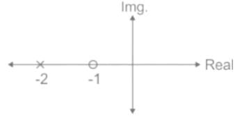
ϕ = tan−1(ω/1) − tan−1(ω/2)
i.e., phase angle will be positive for ω > 0
similarly, for lag compensator: Hc(s) = s+2/s+1
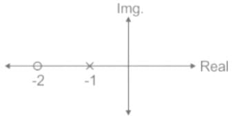
ϕ = tan−1(ω/2) −tan−1(ω)
i.e. phase angle is negative for ω > 0.
Now,
For lead compensator, gain crossover frequency (ωgc) increase which causes an increase in B.W. and hence the speed of the system improves.
For lag compensator; Gain crossover frequency (ωpc) decreases which causes decreases in B.W. and hence speed of the system decreases.
We know:
Hc(s) = s+as+b;
when α = zero/pole = α/b is greater than 1 i.e., α > 1 then it is lag compensator.
else when α < 1, then it is lead compensator.
Calculation:
For lead compensator: Hc(s) = s+a/s+b
ϕ = tan−1(ω/1) − tan−1(ω/2)
i.e., phase angle will be positive for ω > 0
similarly, for lag compensator: Hc(s) = s+2/s+1
ϕ = tan−1(ω/2) −tan−1(ω)
i.e. phase angle is negative for ω > 0.
Now,
For lead compensator, gain crossover frequency (ωgc) increase which causes an increase in B.W. and hence the speed of the system improves.
For lag compensator; Gain crossover frequency (ωpc) decreases which causes decreases in B.W. and hence speed of the system decreases.
A step-up chopper is used to deliver load voltage of 500 V from a 220 V d.c. source. If the blocking period of the thyristor is 80 μs, the required pulse width is- a)101.8 μs
- b)50.8 μs
- c)152.4 μs
- d)92.4 μs
Correct answer is option 'A'. Can you explain this answer?
A step-up chopper is used to deliver load voltage of 500 V from a 220 V d.c. source. If the blocking period of the thyristor is 80 μs, the required pulse width is
a)
101.8 μs
b)
50.8 μs
c)
152.4 μs
d)
92.4 μs
|
|
Poulomi Ahuja answered |
The blocking period of the thyristor refers to the time when the thyristor is turned off and no current flows through it. In a step-up chopper, the thyristor is used to control the voltage delivered to the load.
To determine the blocking period, we need to know the switching frequency of the thyristor. Let's assume the switching frequency is given as 100 Hz.
The blocking period can be calculated using the formula:
Blocking Period = 1 / Switching Frequency
Blocking Period = 1 / 100 Hz = 0.01 seconds
Therefore, the blocking period of the thyristor is 0.01 seconds (or 10 milliseconds).
The last and the first stages in a superheterodyne receiver are respectively- a)IF amplifier and AF amplifier
- b)RF amplifier and AF amplifier
- c)Mixer and R.F. amplifier
- d)A.F. amplifier and R.F. amplifier
Correct answer is option 'D'. Can you explain this answer?
The last and the first stages in a superheterodyne receiver are respectively
a)
IF amplifier and AF amplifier
b)
RF amplifier and AF amplifier
c)
Mixer and R.F. amplifier
d)
A.F. amplifier and R.F. amplifier
|
|
Anjana Singh answered |
The superheterodyne receiver works by converting the received radio frequency signal to a fixed intermediate frequency (IF) for further processing. The process involves mixing the incoming RF signal with a locally generated oscillator signal in a mixer, resulting in the production of the IF signal.
After the mixing process, the IF signal goes through several stages of amplification, filtering, and detection. The A.F. amplifier is the last stage in the receiver, responsible for amplifying the demodulated audio signal to a suitable level for driving a speaker or other audio output devices.
On the other hand, the R.F. amplifier is the first stage in the receiver, situated before the mixing process. Its purpose is to amplify the weak RF signal received by the antenna to a sufficient level before it enters the mixer.
Therefore, the correct answer is D: A.F. amplifier and R.F. amplifier, as it correctly identifies the last and first stages in a superheterodyne receiver.
The line current flowing in the lines toward a balanced load connected in delta are Ia = 100∠0°, Ib = 141.4∠225°, Ic = 100∠90°. Find the symmetrical component of the line current.- a)Ia0 = 0.07∠115°, Ia1 = 121∠150°, Ia2 = 209.88∠5°
- b)Ia0 = 7∠125°, Ia1 = 211∠125°, Ia2 = 229.88∠150°
- c)Ia0 = 0.007∠45°, Ia1 = 111∠15°, Ia2 = 29.88∠105°
- d)Ia0 = 0.7∠145°, Ia1 = 131∠105°, Ia2 = 290.88∠10°
Correct answer is option 'C'. Can you explain this answer?
The line current flowing in the lines toward a balanced load connected in delta are Ia = 100∠0°, Ib = 141.4∠225°, Ic = 100∠90°. Find the symmetrical component of the line current.
a)
Ia0 = 0.07∠115°, Ia1 = 121∠150°, Ia2 = 209.88∠5°
b)
Ia0 = 7∠125°, Ia1 = 211∠125°, Ia2 = 229.88∠150°
c)
Ia0 = 0.007∠45°, Ia1 = 111∠15°, Ia2 = 29.88∠105°
d)
Ia0 = 0.7∠145°, Ia1 = 131∠105°, Ia2 = 290.88∠10°
|
|
Yash Patel answered |
The relation between the line currents in terms of the symmetrical components of currents is given below.
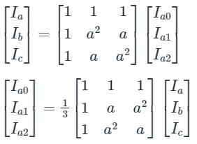
Ia0 = Zero Sequence Component of Current
Ia1 = Positive Sequence Component of Current
Ia2 = Negative Sequence Component of Current
a = 1∠120°, which represents the rotation of 120° in clockwise direction.
a2 = 1∠-120° or 1∠240° in anticlockwise direction or in clockwise direction, respectively.
Ia0 = Zero Sequence Component of Current
Ia1 = Positive Sequence Component of Current
Ia2 = Negative Sequence Component of Current
a = 1∠120°, which represents the rotation of 120° in clockwise direction.
a2 = 1∠-120° or 1∠240° in anticlockwise direction or in clockwise direction, respectively.
Calculation:
Ia = 100∠0°, Ib = 141.4∠225°, Ic = 100∠90°
Zero sequence component of current,
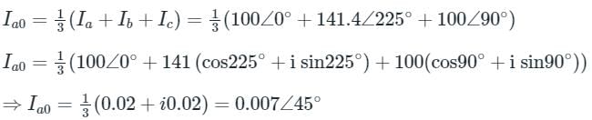
Positive sequence component of current,
Ia = 100∠0°, Ib = 141.4∠225°, Ic = 100∠90°
Zero sequence component of current,
Positive sequence component of current,

⇒ Ia1 = 111∠15°
Negative sequence component of current,
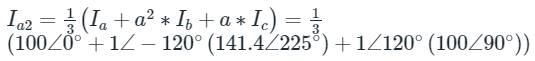
Ia2 = 29.88 ∠ 105°
Loading effect in a voltmeter can be avoided by- a)using high voltage range
- b)using an accurate and precise instrument
- c)using a high sensitive voltmeter
- d)using a low sensitive voltmeter
Correct answer is option 'C'. Can you explain this answer?
Loading effect in a voltmeter can be avoided by
a)
using high voltage range
b)
using an accurate and precise instrument
c)
using a high sensitive voltmeter
d)
using a low sensitive voltmeter
|
|
Ishani Iyer answered |
Introduction:
Loading effect refers to the alteration of the measured quantity due to the presence of the measuring instrument in the circuit. In the case of a voltmeter, the loading effect occurs when the internal resistance of the voltmeter circuit affects the voltage being measured. To avoid or minimize this loading effect, certain measures can be taken.
Explanation:
The correct answer to avoid the loading effect in a voltmeter is option 'C', i.e., using a high sensitive voltmeter. Here's an explanation of why this is the correct choice:
1. Understanding the Loading Effect:
When a voltmeter is connected in parallel to a circuit, it acts as a load and draws some current from the circuit. This current flows through the internal resistance of the voltmeter, causing a voltage drop. As a result, the voltage being measured by the voltmeter is slightly lower than the actual voltage in the circuit.
2. Importance of Sensitivity:
The sensitivity of a voltmeter is a measure of its ability to detect and display small changes in voltage. A high sensitive voltmeter can measure small voltages accurately without significantly affecting the circuit being measured. On the other hand, a low sensitive voltmeter may draw more current from the circuit, resulting in a larger loading effect.
3. Effect of Sensitivity on Internal Resistance:
A high sensitive voltmeter typically has a very high input impedance or internal resistance. The input impedance of a voltmeter is the resistance that it presents to the circuit being measured. A higher input impedance means that the voltmeter draws less current from the circuit, minimizing the loading effect.
4. Alternate Options:
The other options provided in the question, such as using a high voltage range or an accurate and precise instrument, do not directly address the loading effect issue. While using a high voltage range may prevent the voltmeter from saturating, it does not necessarily minimize the loading effect. Similarly, an accurate and precise instrument ensures accurate measurements but does not directly address the loading effect.
Conclusion:
To avoid or minimize the loading effect in a voltmeter, it is important to use a high sensitive voltmeter with a high input impedance. This ensures that the voltmeter draws minimal current from the circuit being measured, resulting in more accurate voltage measurements.
What is the temperature at which a change from the anti-ferromagnetic phase to paramagnetic phase occurs?- a)Weiss
- b)Curie
- c)Neel
- d)Debye
Correct answer is option 'B'. Can you explain this answer?
What is the temperature at which a change from the anti-ferromagnetic phase to paramagnetic phase occurs?
a)
Weiss
b)
Curie
c)
Neel
d)
Debye
|
|
Ravi Singh answered |
Neel temperature is defined as that temperature at which materials lose their magnetic ordering due to large thermal energy. In other words, a transition from the anti-ferromagnetic state to paramagnetic phase occurs. This is otherwise also known as magnetic ordering temperature and is named after Louis Neel.
Calculate the emf when a coil of 100 turns is subjected to a flux rate of 0.3 tesla/sec.- a)3
- b)30
- c)-30
- d)-300
Correct answer is option 'C'. Can you explain this answer?
Calculate the emf when a coil of 100 turns is subjected to a flux rate of 0.3 tesla/sec.
a)
3
b)
30
c)
-30
d)
-300
|
|
Pooja Patel answered |
The induced emf is given by Vemf = -dλ/dt = -Ndψ/dt. Thus emf will be -100 x 0.3 = -30 units.
The realization of FIR filter by frequency sampling realization can be viewed as cascade of how many filters?- a)Two
- b)Three
- c)Four
- d)None of the mentioned
Correct answer is option 'A'. Can you explain this answer?
The realization of FIR filter by frequency sampling realization can be viewed as cascade of how many filters?
a)
Two
b)
Three
c)
Four
d)
None of the mentioned
|
|
Nilesh Joshi answered |
Introduction:
The frequency sampling method is a technique used for the realization of Finite Impulse Response (FIR) filters. It involves sampling the desired frequency response of the filter and then finding the corresponding impulse response using the inverse discrete Fourier transform (IDFT). The resulting impulse response is then used to implement the FIR filter.
Frequency Sampling Method:
The frequency sampling method involves the following steps:
1. Determine the desired frequency response of the FIR filter.
2. Sample the desired frequency response at equally spaced frequencies.
3. Perform the IDFT on the sampled frequency response to obtain the corresponding impulse response.
4. Implement the FIR filter using the obtained impulse response.
Cascade of Filters:
When applying the frequency sampling method, the realization of the FIR filter can be viewed as a cascade of two filters. This can be understood by considering the steps involved in the frequency sampling method.
First Filter:
The first filter in the cascade is responsible for generating the sampled frequency response. It takes the desired frequency response as input and produces the sampled frequency response. This filter essentially performs the sampling operation by assigning the values of the desired frequency response at equally spaced frequencies.
Second Filter:
The second filter in the cascade is responsible for converting the sampled frequency response into the impulse response. It takes the sampled frequency response as input and performs the IDFT to obtain the corresponding impulse response.
Overall Cascade:
The output of the first filter (sampled frequency response) serves as the input to the second filter (IDFT operation). The output of the second filter (impulse response) represents the final realization of the FIR filter. Therefore, the realization of the FIR filter by frequency sampling can be viewed as a cascade of two filters.
Conclusion:
In conclusion, the realization of a FIR filter by frequency sampling can be viewed as a cascade of two filters. The first filter generates the sampled frequency response, and the second filter converts the sampled frequency response into the impulse response. This cascade of filters allows for the implementation of the desired FIR filter using the frequency sampling method.
With the potential difference between the source and the drain kept small (VDS is small), the MOSFET behaves as a resistance whose value varies __________ with the overdrive voltage- a)Linearly
- b)Inversely
- c)Exponentially
- d)Logarithmically
Correct answer is option 'B'. Can you explain this answer?
With the potential difference between the source and the drain kept small (VDS is small), the MOSFET behaves as a resistance whose value varies __________ with the overdrive voltage
a)
Linearly
b)
Inversely
c)
Exponentially
d)
Logarithmically
|
|
Pankaj Mehta answered |
The behavior of a MOSFET (Metal-Oxide-Semiconductor Field-Effect Transistor) in the saturation region, where the potential difference between the source and the drain (VDS) is small, can be described in terms of its resistance.
When the MOSFET is operating in the saturation region, the channel between the source and the drain is fully open, allowing current to flow freely. In this region, the MOSFET can be modeled as a resistance, known as the channel resistance or on-resistance (RON). The value of RON varies with the overdrive voltage (Vov), which is the difference between the gate voltage and the threshold voltage.
Explanation:
- The resistance value of the MOSFET varies inversely with the overdrive voltage. This means that as the overdrive voltage increases, the resistance of the MOSFET decreases, and vice versa.
- The overdrive voltage is a measure of how far the gate voltage exceeds the threshold voltage. When the overdrive voltage is large, the MOSFET is fully turned on, and the resistance is small. As the overdrive voltage decreases, the MOSFET starts to turn off, and the resistance increases.
- This behavior can be explained by the operation of the MOSFET. When the gate voltage is higher than the threshold voltage, a channel is formed between the source and the drain, allowing current to flow. The width of this channel depends on the overdrive voltage.
- As the overdrive voltage increases, the channel width increases, resulting in a lower resistance. Conversely, as the overdrive voltage decreases, the channel width decreases, leading to a higher resistance.
- Therefore, the resistance of the MOSFET varies inversely with the overdrive voltage.
Telephone companies make use of the Wheatstone bridge for _________.- a)measuring the telephone resistance
- b)computing the line strength
- c)maintaining Dialtone
- d)locating the cable faults
Correct answer is option 'D'. Can you explain this answer?
Telephone companies make use of the Wheatstone bridge for _________.
a)
measuring the telephone resistance
b)
computing the line strength
c)
maintaining Dialtone
d)
locating the cable faults
|
|
Zoya Sharma answered |
Cable faults in telephones can be located by telephone companies using a Wheatstone bridge. Telephonic resistances are determined using suitable techniques. Dialtone is maintained through optical fiber technology.
A recording of the output of the emf induced for star and delta are recorded.Then shape of the emf induced in Y-connected 3-phase transformer is non sinusoidal in nature due to- a)3rd harmonic component of currents is absent
- b)3rd harmonic component of currents is present
- c)negative sequence component of current is present
- d)none of the mentioned
Correct answer is option 'A'. Can you explain this answer?
A recording of the output of the emf induced for star and delta are recorded.Then shape of the emf induced in Y-connected 3-phase transformer is non sinusoidal in nature due to
a)
3rd harmonic component of currents is absent
b)
3rd harmonic component of currents is present
c)
negative sequence component of current is present
d)
none of the mentioned
|
|
Nandita Kulkarni answered |
Explanation:
In a Y-connected 3-phase transformer, the emf induced in each phase is non-sinusoidal in nature due to the absence of the 3rd harmonic component of currents.
Reason:
The shape of the emf induced in a Y-connected 3-phase transformer is determined by the nature of the currents flowing through the windings. In a balanced three-phase system, the currents in the three phases are sinusoidal and have a fundamental frequency. However, they also contain harmonic components at multiples of the fundamental frequency.
Star Connection:
In a star-connected system, the three windings are connected together at a common neutral point, forming a Y-shaped configuration. The current flowing through each winding is divided into two paths - one path through the winding itself and the other path through the common neutral point.
Delta Connection:
In a delta-connected system, the three windings are connected in a closed-loop, forming a triangular or delta-shaped configuration. The current flowing through each winding is the actual current flowing through that winding.
Induced EMF:
The emf induced in each winding of a transformer is directly proportional to the rate of change of flux linkage. In a Y-connected transformer, the flux linkage in each winding is determined by the current flowing through that winding.
Non-Sinusoidal Nature:
In a Y-connected transformer, the absence of the 3rd harmonic component of currents results in a non-sinusoidal shape of the induced emf. The 3rd harmonic component of currents is absent because the 3rd harmonic currents flowing through the windings cancel out at the common neutral point in a Y-connected system.
Conclusion:
Therefore, the shape of the emf induced in a Y-connected 3-phase transformer is non-sinusoidal in nature due to the absence of the 3rd harmonic component of currents.
A 400 V, 10 KVA transformer at 50 Hz, is operated at the frequency of 40 Hz, then the humming- a)increases
- b)decreases
- c)remains same
- d)increases to very high
Correct answer is option 'A'. Can you explain this answer?
A 400 V, 10 KVA transformer at 50 Hz, is operated at the frequency of 40 Hz, then the humming
a)
increases
b)
decreases
c)
remains same
d)
increases to very high
|
|
Ravi Singh answered |
The humming or audible noise produced by a transformer is mainly caused by the magnetostriction effect. Magnetostriction is the phenomenon where a material undergoes mechanical deformation in response to changes in the magnetic field.
In a transformer, the core experiences cyclic magnetization due to the alternating current. This causes the core to expand and contract, generating vibrations that result in audible noise or humming.
When the frequency of operation is decreased from 50 Hz to 40 Hz, the rate at which the magnetic field changes also decreases. This slower rate of change leads to a longer duration for each expansion and contraction cycle of the core. As a result, the vibrations and audible noise produced by the magnetostriction effect are more noticeable at the lower frequency.
Therefore, when a 400 V, 10 KVA transformer operating at 50 Hz is operated at a frequency of 40 Hz, the humming is expected to increase.
A thyristor (SCR) is a- a)P-N-P device
- b)N-P-N device
- c)P-N-P-N device
- d)P-N device
Correct answer is option 'C'. Can you explain this answer?
A thyristor (SCR) is a
a)
P-N-P device
b)
N-P-N device
c)
P-N-P-N device
d)
P-N device
|
|
Anjana Singh answered |
An SCR (silicon controlled rectifier) is a four layer p-n-p-n type device.
In a 100 bus power system, there are 10 generators. In a particular iteration of Newton Raphson load flow technique (in polar coordinates), two of the PV buses are converted to PQ type. In this iteration,- a)the number of unknown voltage angles increases by two and the number of unknown voltage magnitudes increases by two.
- b)the number of unknown voltage angles remains unchanged and the number of unknown voltage magnitudes increases by two.
- c)the number of unknown voltage angles increases by two and the number of unknown voltage magnitudes decreases by two.
- d)the number of unknown voltage angles remains unchanged and the number of unknown voltage magnitudes decreases by two.
Correct answer is option 'B'. Can you explain this answer?
In a 100 bus power system, there are 10 generators. In a particular iteration of Newton Raphson load flow technique (in polar coordinates), two of the PV buses are converted to PQ type. In this iteration,
a)
the number of unknown voltage angles increases by two and the number of unknown voltage magnitudes increases by two.
b)
the number of unknown voltage angles remains unchanged and the number of unknown voltage magnitudes increases by two.
c)
the number of unknown voltage angles increases by two and the number of unknown voltage magnitudes decreases by two.
d)
the number of unknown voltage angles remains unchanged and the number of unknown voltage magnitudes decreases by two.

|
Isha Bajaj answered |
Explanation:
In a Newton Raphson load flow technique, the power system is represented as a set of equations in polar coordinates. The unknowns in these equations are the voltage magnitudes and voltage angles at each bus.
Given:
- Total buses in the system = 100
- Number of generators = 10
- PV buses converted to PQ type = 2
Analysis:
In a power system, each generator is represented as a PV (constant voltage, constant power) bus. In a PV bus, the voltage magnitude and real power output are known, while the voltage angle and reactive power are unknowns.
Step 1: Calculation of unknowns
- Total number of unknown voltage angles = Total buses - Number of known voltage angles
- Total number of unknown voltage magnitudes = Total buses - Number of known voltage magnitudes
In the given system:
- Initial unknown voltage angles = 100 - 10 = 90
- Initial unknown voltage magnitudes = 100 - 10 = 90
Step 2: Conversion of PV buses to PQ type
When two PV buses are converted to PQ type, the known voltage magnitudes become unknowns, while the voltage angles remain unknown.
- Number of known voltage magnitudes = Number of generators - Number of PV buses converted to PQ type = 10 - 2 = 8
Step 3: Calculation of unknowns after conversion
- After conversion, the number of unknown voltage angles remains unchanged as the voltage angles at all buses are still unknowns.
- The number of unknown voltage magnitudes increases by two because the PV buses that were previously known now become unknowns.
Final calculation of unknowns:
- Final number of unknown voltage angles = Initial unknown voltage angles = 90
- Final number of unknown voltage magnitudes = Initial unknown voltage magnitudes + Number of unknown voltage magnitudes after conversion = 90 + 2 = 92
Conclusion:
From the above analysis, it is clear that in the given iteration of the Newton Raphson load flow technique, the number of unknown voltage angles remains unchanged, and the number of unknown voltage magnitudes increases by two. Therefore, the correct answer is option 'B'.
ALU (Arithmetic Logic Unit) of an 8085 microprocessor consists of :- a) Accumulator, temporary register, arithmetic and logic circuits.
- b)Accumulator, arithmetic, logic circuits and five flags.
- c)Accumulator, arithmetic and logic circuits.
- d)Accumulator, temporary resister, arithmetic, logic circuits & five flags
Correct answer is option 'D'. Can you explain this answer?
ALU (Arithmetic Logic Unit) of an 8085 microprocessor consists of :
a)
Accumulator, temporary register, arithmetic and logic circuits.
b)
Accumulator, arithmetic, logic circuits and five flags.
c)
Accumulator, arithmetic and logic circuits.
d)
Accumulator, temporary resister, arithmetic, logic circuits & five flags
|
|
Anjana Singh answered |
The ALU (Arithmetic Logic Unit) of an 8085 microprocessor consists of an accumulator, temporary register, arithmetic and logic circuits, and five flags.
The ALU is a fundamental component of a microprocessor that performs arithmetic operations (such as addition, subtraction, multiplication, and division) and logical operations (such as AND, OR, XOR) on binary data. The ALU processes data stored in registers and produces results based on the given instructions.
Let's analyze each option to understand why option D is the correct answer:
Option A: This option states that the ALU consists of an accumulator, temporary register, arithmetic, and logic circuits. While it includes some of the essential components of an ALU, it does not mention the presence of flags. Flags are special registers that store the results of certain operations or indicate specific conditions, such as carry, zero, sign, and overflow flags.
Option B: This option states that the ALU consists of an accumulator, arithmetic, logic circuits, and five flags. It includes all the necessary components of an ALU, including the flags that store information about the results of operations and specific conditions.
Option C: This option states that the ALU consists of an accumulator, arithmetic, and logic circuits. It does not mention the presence of temporary registers or flags, which are vital components of an ALU.
Option D: This option states that the ALU consists of an accumulator, temporary register, arithmetic, logic circuits, and five flags. It includes all the essential components of an 8085 microprocessor's ALU, which are necessary for performing arithmetic and logical operations and storing flags to indicate various conditions.
Considering the above analysis, we can conclude that option D, which states that the ALU consists of an accumulator, temporary register, arithmetic, logic circuits, and five flags, is the correct answer.
Therefore, the correct answer is D: Accumulator, temporary register, arithmetic, logic circuits, and five flags.
The phenomena of ‘limit cycles’ and ‘jump resonance’ are observed in- a)linear systems
- b)distributed systems
- c)non-linear systems
- d)discrete time systems
Correct answer is option 'C'. Can you explain this answer?
The phenomena of ‘limit cycles’ and ‘jump resonance’ are observed in
a)
linear systems
b)
distributed systems
c)
non-linear systems
d)
discrete time systems
|
|
Anirban Chawla answered |
The phenomena of phenomena refers to the observable events or occurrences that happen in the world. These phenomena can range from natural occurrences like weather patterns or animal behavior, to human-made events such as cultural practices or technological advancements.
Phenomena can be studied and analyzed through various scientific disciplines and methodologies. Scientists and researchers strive to understand the underlying causes and mechanisms behind these phenomena, as well as their effects and implications.
Some examples of phenomena include:
- Natural disasters: Hurricanes, earthquakes, and volcanic eruptions are natural phenomena that can have significant impacts on the environment and human populations.
- Biological processes: Phenomena like photosynthesis, cell division, and animal migration are fundamental to life on Earth and are studied in fields such as biology and ecology.
- Social trends: Cultural phenomena like fashion trends, music genres, and social media movements reflect the collective behavior and preferences of a society.
- Technological advancements: The development of new technologies, such as smartphones, artificial intelligence, and renewable energy sources, are phenomena that shape and transform our daily lives.
Understanding and studying phenomena is crucial for advancing scientific knowledge, improving our understanding of the world, and finding solutions to various challenges and problems.
How can the meter circuit be isolated from the power circuit?- a)by grounding
- b)through electrical isolation
- c)by physical separation
- d)through mechanical isolation
Correct answer is option 'B'. Can you explain this answer?
How can the meter circuit be isolated from the power circuit?
a)
by grounding
b)
through electrical isolation
c)
by physical separation
d)
through mechanical isolation
|
|
Yash Patel answered |
Leads of the secondary winding transformer are brought to the switch board thus separating them from high voltage windings. In this way, the meter circuit is isolated from the high voltage power circuit.
The wattage of motor for driving domestic sewing machine will be around- a)100 to 150 W
- b)40 to 75 W
- c)10 to 30 W
- d)5 to 10 W
Correct answer is option 'A'. Can you explain this answer?
The wattage of motor for driving domestic sewing machine will be around
a)
100 to 150 W
b)
40 to 75 W
c)
10 to 30 W
d)
5 to 10 W
|
|
Yash Patel answered |
- The wattage of a motor for driving a domestic sewing machine typically falls within the range of 100 to 150 watts. Domestic sewing machines are designed for light to medium-duty sewing tasks, and their motors are usually small and low-power to meet the requirements of sewing fabrics and light materials.
- The wattage range of 100 to 150 watts provides enough power to drive the sewing machine's mechanism, allowing it to stitch various types of fabrics effectively without consuming excessive energy.
- Therefore, the correct answer is A: 100 to 150 W.
If the current through a moving iron instrument is increased by 20%, what is the percentage increase in the deflection torque?- a)40
- b)25
- c)32
- d)44
Correct answer is option 'D'. Can you explain this answer?
If the current through a moving iron instrument is increased by 20%, what is the percentage increase in the deflection torque?
a)
40
b)
25
c)
32
d)
44
|
|
Ritika Mukherjee answered |
Given:
- The current through a moving iron instrument is increased by 20%.
To find:
- The percentage increase in the deflection torque.
Solution:
The deflection torque in a moving iron instrument is given by the equation:
T = kΦIn
where T is the deflection torque, k is a constant, Φ is the magnetic flux, and I is the current.
We can rewrite this equation as:
T = k'Φ'I'
where k' is a new constant, Φ' is the new magnetic flux, and I' is the new current.
Step 1:
Let's assume the initial current is I and the final current is I'. We are given that the current is increased by 20%, which can be expressed as:
I' = I + 0.2I
= 1.2I
Step 2:
Now, let's assume the initial deflection torque is T and the final deflection torque is T'. We need to find the percentage increase in the deflection torque, which can be expressed as:
Percentage increase in T = ((T' - T) / T) * 100
Step 3:
Substituting the values of T and T' from the equations above, we get:
Percentage increase in T = ((k'Φ'I' - kΦI) / kΦI) * 100
Step 4:
Since k, Φ, and k'Φ' are constant, we can simplify the equation to:
Percentage increase in T = ((I' - I) / I) * 100
Step 5:
Substituting the value of I' from Step 1, we have:
Percentage increase in T = ((1.2I - I) / I) * 100
= (0.2I / I) * 100
= 20%
Conclusion:
Therefore, the percentage increase in the deflection torque is 20%. However, none of the given options match this answer. Hence, the question might have been misquoted or there may be some other error.
Which of the following motors is non-self starting?- a)D.C. series motor
- b)synchronous motor
- c)Squirrel cage induction motor
- d)Wound round induction motor
Correct answer is option 'B'. Can you explain this answer?
Which of the following motors is non-self starting?
a)
D.C. series motor
b)
synchronous motor
c)
Squirrel cage induction motor
d)
Wound round induction motor
|
|
Bijoy Nair answered |
Non-Self Starting Motors
Introduction:
In the field of electrical engineering, different types of motors are used for various applications. One important classification of motors is based on their self-starting capability. A self-starting motor is one that can start on its own without any external assistance. On the other hand, a non-self starting motor requires external assistance to start and achieve a running condition. Among the given options, the synchronous motor is a non-self starting motor.
Synchronous Motor:
A synchronous motor is a type of AC motor that operates at a synchronous speed, which is directly proportional to the frequency of the power supply and inversely proportional to the number of poles in the motor. The synchronous motor requires external assistance to start and synchronize with the power supply before it can operate on its own.
Working Principle:
- The synchronous motor has two main components: a stator and a rotor.
- The stator consists of field windings that produce a rotating magnetic field when connected to an AC power supply.
- The rotor is a cylindrical structure with salient poles, and it carries direct current (DC) to create a magnetic field.
- When the stator magnetic field interacts with the rotor magnetic field, torque is produced, causing the motor to rotate.
Non-Self Starting Nature:
The synchronous motor is non-self starting due to the following reasons:
- When the synchronous motor is initially connected to the power supply, the stator magnetic field starts rotating. However, the rotor poles are not aligned with the stator poles.
- As a result, there is no torque generated, and the motor cannot start on its own.
- To make the motor start, external means such as a starting motor or a prime mover (e.g., another motor) are required to bring the rotor close to the synchronous speed.
- Once the rotor speed matches the synchronous speed, synchronization occurs, and the motor can continue to operate independently.
Conclusion:
Among the given options, the synchronous motor is the non-self starting motor. It requires external assistance to start and synchronize with the power supply. Once synchronized, it can operate independently.
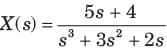
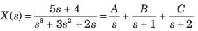
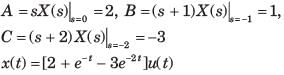
How many number of butterflies are required per output point in FFT algorithm?- a)N
- b)N+1
- c)2N
- d)N-1
Correct answer is option 'D'. Can you explain this answer?
How many number of butterflies are required per output point in FFT algorithm?
a)
N
b)
N+1
c)
2N
d)
N-1
|
|
Zoya Sharma answered |
We find that, in general, there are N/2 in the first stage of FFT, N/4 in the second stage, N-8 in the third state, and so on, until the last stage where there is only one. Consequently, the number of butterflies per output point is N-1.
A properly shunted centre-zero galvanometer is connected in the rotor circuit of a 6-pole, 50 Hz would-rotor induction motor. If the galvanometer makes 90 complete oscillations in one minute, the speed of rotor would be- a)1000 rpm
- b)740 rpm
- c)880 rpm
- d)970 rpm
Correct answer is option 'D'. Can you explain this answer?
A properly shunted centre-zero galvanometer is connected in the rotor circuit of a 6-pole, 50 Hz would-rotor induction motor. If the galvanometer makes 90 complete oscillations in one minute, the speed of rotor would be
a)
1000 rpm
b)
740 rpm
c)
880 rpm
d)
970 rpm
|
|
Vaishnavi Singh answered |
Given Data:
- Number of poles (P) = 6
- Frequency (f) = 50 Hz
- Number of oscillations in one minute = 90
Calculations:
1. Calculate synchronous speed (Ns) using the formula:
Ns = (120 * f) / P
Ns = (120 * 50) / 6
Ns = 1000 rpm
2. Calculate actual speed of rotor using the formula:
Actual speed = (Number of oscillations * Ns) / 60
Actual speed = (90 * 1000) / 60
Actual speed = 1500 rpm
3. Since the galvanometer makes 90 complete oscillations in one minute, it indicates the speed of the rotor would be half the actual speed:
Rotor speed = 1500 / 2
Rotor speed = 750 rpm
Conclusion:
Therefore, the speed of the rotor would be 750 rpm, which is closest to option 'D' (970 rpm).
Which of the following motors has two separate windings on the motor ?- a)Repulsion motor
- b)Repulsion induction motor
- c)Repulsion start induction run motor
- d)None of the above
Correct answer is option 'B'. Can you explain this answer?
Which of the following motors has two separate windings on the motor ?
a)
Repulsion motor
b)
Repulsion induction motor
c)
Repulsion start induction run motor
d)
None of the above
|
|
Divya Nair answered |
Repulsion Induction Motor
Repulsion induction motors have two separate windings on the motor, making them the correct option from the given choices.
Explanation:
Construction:
- A repulsion induction motor consists of two windings, one is the main winding, and the other is the auxiliary winding.
- The main winding is a repulsion winding, and the auxiliary winding is an induction winding.
- Both windings are placed in the stator of the motor.
Operation:
- When the motor is started, both windings are energized.
- The repulsion winding creates a magnetic field that causes the rotor to rotate.
- As the rotor gains speed, the motor automatically switches from repulsion to induction mode.
- The motor then operates as an induction motor with the help of the auxiliary winding.
Advantages:
- Repulsion induction motors provide high starting torque.
- They have a simple and robust construction.
- These motors are suitable for applications where high starting torque is required.
Applications:
- Repulsion induction motors are commonly used in applications such as air compressors, conveyors, and pumps.
In conclusion, the repulsion induction motor is the type of motor that has two separate windings - a repulsion winding and an induction winding. It offers high starting torque and is suitable for various industrial applications.
Omega Electronics sells a microwave receiver
(A) having an operating spot noise figure of 10 dB when driven by a source with effective noise temperature 130 K Digilink
(B) sells a receiver with a standard spot noise figure of 6 dB. Microtronics
(C) sells a receiver with standard spot noise figure of 8 dB when driven by a source with effective noise temperature 190 K. The best receiver to purchase is- a)A
- b)B
- c)C
- d)All are equal
Correct answer is option 'B'. Can you explain this answer?
Omega Electronics sells a microwave receiver
(A) having an operating spot noise figure of 10 dB when driven by a source with effective noise temperature 130 K Digilink
(B) sells a receiver with a standard spot noise figure of 6 dB. Microtronics
(C) sells a receiver with standard spot noise figure of 8 dB when driven by a source with effective noise temperature 190 K. The best receiver to purchase is
a)
A
b)
B
c)
C
d)
All are equal
|
|
Anjana Singh answered |

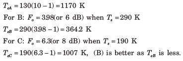
The capital cost on a HVDC converter is- a)less than ac substation
- b)same as ac substation
- c)either less or more than ac substation
- d)more than that of ac substation
Correct answer is option 'D'. Can you explain this answer?
The capital cost on a HVDC converter is
a)
less than ac substation
b)
same as ac substation
c)
either less or more than ac substation
d)
more than that of ac substation
|
|
Ravi Singh answered |
- The capital cost of a High Voltage Direct Current (HVDC) converter station is typically higher than that of an Alternating Current (AC) substation.
- HVDC converter stations require specialized equipment and technology to convert power from AC to DC (at the sending end) and then from DC back to AC (at the receiving end). This includes components such as converters, transformers, filters, and control systems, which are generally more complex and costly compared to the equipment used in AC substations.
- Furthermore, HVDC systems often require additional infrastructure, such as overhead lines or submarine cables, to transmit power over long distances or across bodies of water. These additional transmission costs further contribute to the higher capital cost of HVDC converter stations compared to AC substations.
- Therefore, the correct answer is: D: More than that of an AC substation.
If the resonant frequency in a series RLC circuit is 50kHz along with a bandwidth of 5kHz, find the quality factor.- a)5
- b)50
- c)10
- d)500
Correct answer is option 'C'. Can you explain this answer?
If the resonant frequency in a series RLC circuit is 50kHz along with a bandwidth of 5kHz, find the quality factor.
a)
5
b)
50
c)
10
d)
500
|
|
Anjana Singh answered |
The quality factor (Q) of a series RLC circuit can be calculated using the formula:
Q = Resonant frequency / Bandwidth
In the given scenario, the resonant frequency is 50 kHz, and the bandwidth is 5 kHz.
Q = 50 kHz / 5 kHz Q = 10
Therefore, the correct answer is C: 10. The quality factor of the series RLC circuit is 10.
Dissolved resins in alcohol produce ______ varnishes.- a)Oleoresinous
- b)Phenolic
- c)Spirit
- d)Alkyd
Correct answer is option 'C'. Can you explain this answer?
Dissolved resins in alcohol produce ______ varnishes.
a)
Oleoresinous
b)
Phenolic
c)
Spirit
d)
Alkyd
|
|
Suyash Joshi answered |
Explanation:
Spirit varnishes:
- Dissolved resins in alcohol produce spirit varnishes.
- Spirit varnishes are made by dissolving resins in alcohol, usually ethanol or methanol.
- These varnishes dry quickly due to the evaporation of alcohol, leaving behind a protective resin coating.
- Spirit varnishes are commonly used for wood finishing and in artistic applications.
Types of varnishes:
- Oleoresinous varnishes: These varnishes are made by dissolving resins in a mixture of oil and turpentine or mineral spirits.
- Phenolic varnishes: These varnishes are made by reacting phenol with an aldehyde in the presence of a catalyst.
- Alkyd varnishes: These varnishes are made by reacting a polyol with a dicarboxylic acid or anhydride.
Properties of spirit varnishes:
- Spirit varnishes have good clarity and color retention.
- They dry quickly and are easy to apply.
- They provide a hard and durable finish.
- Spirit varnishes are suitable for interior woodwork, musical instruments, and other delicate surfaces.
In conclusion, dissolved resins in alcohol produce spirit varnishes, which are known for their quick drying time and protective resin coating. These varnishes are commonly used in wood finishing and artistic applications.
Chapter doubts & questions for Paper-II (ESE Electrical) - Engineering Services Examination (ESE) Mock Test Series 2025 2025 is part of Electrical Engineering (EE) exam preparation. The chapters have been prepared according to the Electrical Engineering (EE) exam syllabus. The Chapter doubts & questions, notes, tests & MCQs are made for Electrical Engineering (EE) 2025 Exam. Find important definitions, questions, notes, meanings, examples, exercises, MCQs and online tests here.
Chapter doubts & questions of Paper-II (ESE Electrical) - Engineering Services Examination (ESE) Mock Test Series 2025 in English & Hindi are available as part of Electrical Engineering (EE) exam.
Download more important topics, notes, lectures and mock test series for Electrical Engineering (EE) Exam by signing up for free.

Signup to see your scores go up within 7 days!
Study with 1000+ FREE Docs, Videos & Tests
10M+ students study on EduRev
|
© EduRev
|
Education Revolution
|


|


Signup to see your scores
go up within 7 days!
Access 1000+ FREE Docs, Videos and Tests
Takes less than 10 seconds to signup