


All Exams >
UPSC >
Electrical Engineering Optional Notes for UPSC >
All Questions
All questions of Circuit components for UPSC CSE Exam
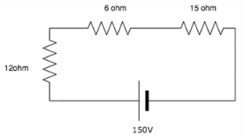
Find the voltage across the 6 ohm resistor.
- a)150V
- b)181,6V
- c) 27.24V
- d)54.48V
Correct answer is option 'C'. Can you explain this answer?
Find the voltage across the 6 ohm resistor.
a)
150V
b)
181,6V
c)
27.24V
d)
54.48V

|
Cstoppers Instructors answered |
Total current = 150/(6+12+15) = 4.55A.
V across 6 ohm = Total current x resistance
= 4.55 * 6 = 27.24V.

Calculate the total current in the circuit. a)20A
a)20A
b)11.42A
c)12Ad)15ACorrect answer is option 'B'. Can you explain this answer?
|
|
Gargi Basak answered |
The 1 ohm and 2-ohm resistor are in series which is in parallel to the 3-ohm resistor.
The equivalent of these resistances is in series with the 4 ohms and 5-ohm resistor.
Total R= 10.5 ohm. I=V/R= 120/10.5= 11.42A.
The equivalent of these resistances is in series with the 4 ohms and 5-ohm resistor.
Total R= 10.5 ohm. I=V/R= 120/10.5= 11.42A.
Find the current in the circuit. a)1Ab)2Ac)3Ad)4ACorrect answer is option 'B'. Can you explain this answer?
|
|
Nandita Bajaj answered |
I = V/R.
Total resistance = 20+40 = 60ohm.
I = 120V.
I = 120/60 = 2A.
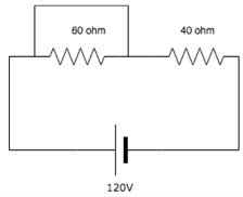
Voltage across the 60ohm resistor is______
- a)72V
- b)0V
- c) 48V
- d) 120V
Correct answer is option 'B'. Can you explain this answer?
Voltage across the 60ohm resistor is______
a)
72V
b)
0V
c)
48V
d)
120V
|
|
Bhavana Reddy answered |
The 60ohm resistance is shorted since current always choses the low resistance path. Voltage across short circuit is equal to zero, hence voltage across the resistor is 0.
Calculate the equivalent resistance between A and B.

- a) 60 ohm
- b) 15 ohm
- c)12 ohm
- d)48 ohm
Correct answer is option 'C'. Can you explain this answer?
Calculate the equivalent resistance between A and B.
a)
60 ohm
b)
15 ohm
c)
12 ohm
d)
48 ohm
|
|
Akanksha Chopra answered |
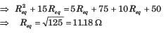
The 5 ohm and 15 ohm resistances are connected in series and 10 ohm and 20 ohm resistors are also connected in series. Therefore,20 ohm and 30 ohm are parallel with each other.
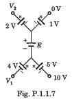
In the circuit of the fig P1.1.7, the value of the voltage source E is
- a)-16 V
- b)4 V
- c)-6 V
- d)16 V
Correct answer is option 'A'. Can you explain this answer?
In the circuit of the fig P1.1.7, the value of the voltage source E is
a)
-16 V
b)
4 V
c)
-6 V
d)
16 V

|
Gate Funda answered |
Going from 10 V to 0 V
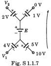
10 + 5 + E + 1 + 0 = 0 or E =-16 V
10 + 5 + E + 1 + 0 = 0 or E =-16 V
Can you explain the answer of this question below:What is the value of x if the current in the circuit is 5A?
 A:15 ohmB:65 ohmC:55 ohmD:45 ohmThe answer is a.
|
|
Ishani Iyer answered |
Total voltage=sum of voltages across each resistor. =>150=10*5+5*5+5*x. Solving the equation, we get x=15 ohm.
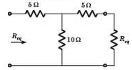
The total resistance between A and B are?
- a)20 ohm
- b)5 ohm
- c)80 ohm
- d)0 ohm
Correct answer is option 'B'. Can you explain this answer?
The total resistance between A and B are?
a)
20 ohm
b)
5 ohm
c)
80 ohm
d)
0 ohm
|
|
Ameya Gupta answered |
The resistors are connected in parallel, hence the equivalent resistance= 1/(1/20=1/20+1/20+1/20)=5ohm.
Calculate the equivalent resistance between A and B.
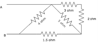
- a) 2 ohm
- b)4 ohm
- c)6 ohm
- d)8 ohm
Correct answer is option 'A'. Can you explain this answer?
Calculate the equivalent resistance between A and B.
a)
2 ohm
b)
4 ohm
c)
6 ohm
d)
8 ohm
|
|
Sharmila Kulkarni answered |
R=((2+3)||5)+1.5)||4.The 2 and the 3 ohm resistor are in series. The equiva-lent of these two resistors is in parallel with the 5 ohm resistor. The equivalent of these three resistances is in series with the 1.5 ohm resistor. Finally, the equivalent of these re-sistances is in parallel with the 4 ohm resistor.
If two bulbs are connected in parallel and one bulb blows out, what happens to the other bulb?- a)The other bulb blows out as well
- b)The other bulb continues to glow with the same brightness
- c)The other bulb glows with increased brightness
- d)The other bulb stops glowing
Correct answer is option 'B'. Can you explain this answer?
If two bulbs are connected in parallel and one bulb blows out, what happens to the other bulb?
a)
The other bulb blows out as well
b)
The other bulb continues to glow with the same brightness
c)
The other bulb glows with increased brightness
d)
The other bulb stops glowing
|
|
Sanchita Sharma answered |
In a parallel circuit, if one bulb blows out, it acts as an open circuit. Current does not flow in that branch but it continues to flow in the other branch hence the bulb continues to glow.
The voltage across the short is?
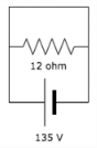
- a)135V
- b)Infinity
- c) Zero
- d)11.25V
Correct answer is option 'C'. Can you explain this answer?
The voltage across the short is?
a)
135V
b)
Infinity
c)
Zero
d)
11.25V
|
|
Sanvi Kapoor answered |
The voltage across a short is always equal to zero whether it is connected in seroes or parallel.
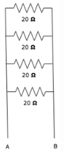
Calculate the current across the 20 ohm resistor.
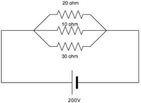
- a)10A
- b) 20A
- c) 36.67A
- d) 6.67A
Correct answer is option 'A'. Can you explain this answer?
Calculate the current across the 20 ohm resistor.
a)
10A
b)
20A
c)
36.67A
d)
6.67A
|
|
Sharmila Bajaj answered |
Explanation: I=V/R. Since in parallel circuit, voltage is same across all resistors. Hence across the 20 ohm resistor, V=200V so I=200/20=10A.
Batteries are generally connected in______- a)Series
- b)Parallel
- c)Either series or parallel
- d)Neither series nor parallel
Correct answer is option 'A'. Can you explain this answer?
Batteries are generally connected in______
a)
Series
b)
Parallel
c)
Either series or parallel
d)
Neither series nor parallel
|
|
Sakshi Roy answered |
Batteries are generally connected in series so that we can obtain the desired voltage since voltages add up once they are connected in series.
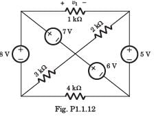
v1 = ?
- a)-11 V
- b)5 V
- c)8 V
- d)18 V
Correct answer is option 'C'. Can you explain this answer?
v1 = ?
a)
-11 V
b)
5 V
c)
8 V
d)
18 V
|
|
Ashwin Kapoor answered |
If we go from +side of 1 kΩ through 7 V, 6 V and 5V, we get v1 = 0 + 7 + 6 - 5 = 8 V
In a series circuit, which of the parameters remain constant across all circuit elements such as resistor, capacitor and inductor etcetera?- a)Voltage
- b)Current
- c)Both voltage and current
- d)Neither voltage nor current
Correct answer is option 'B'. Can you explain this answer?
In a series circuit, which of the parameters remain constant across all circuit elements such as resistor, capacitor and inductor etcetera?
a)
Voltage
b)
Current
c)
Both voltage and current
d)
Neither voltage nor current

|
Swara Dasgupta answered |
In a series circuit, the current across all elements remain the same and the total voltage of the circuit is the sum of the voltages across all the elements.
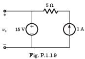
For the circuit shown in fig P.1.1.9 the value of voltage vo is
- a)10 V
- b)15 V
- c)20 V
- d)None of the above
Correct answer is option 'B'. Can you explain this answer?
For the circuit shown in fig P.1.1.9 the value of voltage vo is
a)
10 V
b)
15 V
c)
20 V
d)
None of the above
|
|
Aashna Dey answered |
Voltage is constant because of 15 V source.
What happens to the current in the series circuit if the resistance is doubled?- a)It becomes half its original value
- b)It becomes double its original value
- c)It becomes zero
- d)It becomes infinity
Correct answer is option 'A'. Can you explain this answer?
What happens to the current in the series circuit if the resistance is doubled?
a)
It becomes half its original value
b)
It becomes double its original value
c)
It becomes zero
d)
It becomes infinity
|
|
Rajesh Verma answered |
I=V/R. Hence if R=2R V=I/2R, and I=I/2.
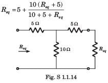
Calculate the resistance between A and B.

- a)3.56 ohm
- b)7 ohm
- c)14.26 ohm
- d)29.69 ohm
Correct answer is option 'A'. Can you explain this answer?
Calculate the resistance between A and B.
a)
3.56 ohm
b)
7 ohm
c)
14.26 ohm
d)
29.69 ohm
|
|
Lavanya Menon answered |
- The 1 ohm, 2 ohm and 3 ohm resistors are connected in parallel. Its equivalent resistance is in series with the 4 ohm resistor and the parallel connection of the 5 ohm and 6 ohm resistor.
- The equivalent resistance of this combination is 80/11 ohm. This is in parallel with 7 ohm to give equivalent resistance between A and B is 3.56 ohm.
If there are two bulbs connected in series and one blows out, what happens to the other bulb?- a)The other bulb continues to glow with the same brightness
- b)The other bulb stops glowing
- c)The other bulb glows with increased brightness
- d)The other bulb also burns out
Correct answer is option 'B'. Can you explain this answer?
If there are two bulbs connected in series and one blows out, what happens to the other bulb?
a)
The other bulb continues to glow with the same brightness
b)
The other bulb stops glowing
c)
The other bulb glows with increased brightness
d)
The other bulb also burns out
|
|
Shivam Das answered |
Explanation:
When two bulbs are connected in series, they share the same current. This means that the current flowing through each bulb is the same.
When one of the bulbs blows out, the circuit is broken and the current can no longer flow through both bulbs. Instead, the current will flow through the path of least resistance, which in this case is the blown-out bulb.
Therefore, the other bulb will stop glowing because there is no longer any current flowing through it.
In summary, when one bulb in a series circuit blows out, the other bulb will stop glowing.
A solid copper sphere, 10 cm in diameter is deprived of 1020 electrons by a charging scheme. The charge on the sphere is
- a)160.2 C
- b)-160.2 C
- c)-16.02 C
- d)16.02 C
Correct answer is option 'C'. Can you explain this answer?
A solid copper sphere, 10 cm in diameter is deprived of 1020 electrons by a charging scheme. The charge on the sphere is
a)
160.2 C
b)
-160.2 C
c)
-16.02 C
d)
16.02 C
|
|
Amar Sengupta answered |
Let's calculate the charge on the sphere
Understanding the problem:
- A copper sphere loses 10^20 electrons.
- We need to find the total charge on the sphere.
Solution:
- Charge of one electron (e) = -1.6 x 10^-19 C
- Number of electrons removed (n) = 10^20
Total charge (Q) = n * e
Q = 1020 * (-1.6 x 10^-19 C) Q = -1.632 x 10^-16 C
Approximately, Q = -16.02 x 10^-17 C
Therefore, the charge on the sphere is -16.02 C.
So, the correct answer is:
4. -16.02 C
Note that the charge is negative because electrons are removed, leaving a net positive charge on the sphere.
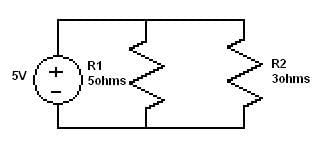
What is the current through R1 and R2 in the following diagram?
- a)I1 =1.875 I2 = 3.125.
- b)
 ,
,  .
.
- c)
 ,
, 
- d)
 ,
,  .
.
Correct answer is option 'A'. Can you explain this answer?
What is the current through R1 and R2 in the following diagram?
a)
I1 =1.875 I2 = 3.125.
b)
, .c)
, d)
, .|
|
Saumya Sen answered |
- All are In parallel so voltage is same
- I1 = ( R2/R1+R2 )V = ( 3/8 )x5A = 1.875
- I2 = ( R1/R1+R2 )V = ( 5/8 )x5A = 3.125
In a parallel circuit, with a number of resistors, the voltage across each resistor is ________- a)The same for all resistors
- b)Is divided equally among all resistors
- c)Is divided proportionally across all resistors
- d)Is zero for all resistors
Correct answer is option 'A'. Can you explain this answer?
In a parallel circuit, with a number of resistors, the voltage across each resistor is ________
a)
The same for all resistors
b)
Is divided equally among all resistors
c)
Is divided proportionally across all resistors
d)
Is zero for all resistors
|
|
Jyoti Basak answered |
In parallel circuits, the current across the circuits vary whereas the voltage remains the same.
What is the voltage measured across a series short?- a)Infinite
- b)Zero
- c)The value of the source voltage
- d)Null
Correct answer is option 'B'. Can you explain this answer?
What is the voltage measured across a series short?
a)
Infinite
b)
Zero
c)
The value of the source voltage
d)
Null
|
|
Om Saini answered |
A short is just a wire. The potential difference between two points of a wire is zero hence the voltage measured is equal to zero.

Voltage across a series resistor circuit is proportional to?- a)The amount of time the circuit was on for
- b)The value of the resistance itself
- c)The value of the other resistances in the circuit
- d)The power in the circuit
Correct answer is option 'B'. Can you explain this answer?
Voltage across a series resistor circuit is proportional to?
a)
The amount of time the circuit was on for
b)
The value of the resistance itself
c)
The value of the other resistances in the circuit
d)
The power in the circuit

|
Shivam Sharma answered |
V=IR hence voltage across a series resistor circuit is proportional to the value of the resistance.
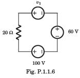
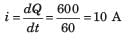
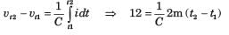
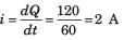
In the circuit of fig P1.1.6 a charge of 600 C is delivered to the 100 V source in a 1 minute. The value of v1 must be
- a)240 V
- b)120 V
- c)60 V
- d)30 V
Correct answer is option 'A'. Can you explain this answer?
In the circuit of fig P1.1.6 a charge of 600 C is delivered to the 100 V source in a 1 minute. The value of v1 must be
a)
240 V
b)
120 V
c)
60 V
d)
30 V
|
|
Cstoppers Instructors answered |
In order for 600 C charge to be delivered to the 100 V source, the current must be anticlockwise.
Applying KVL we get

Applying KVL we get
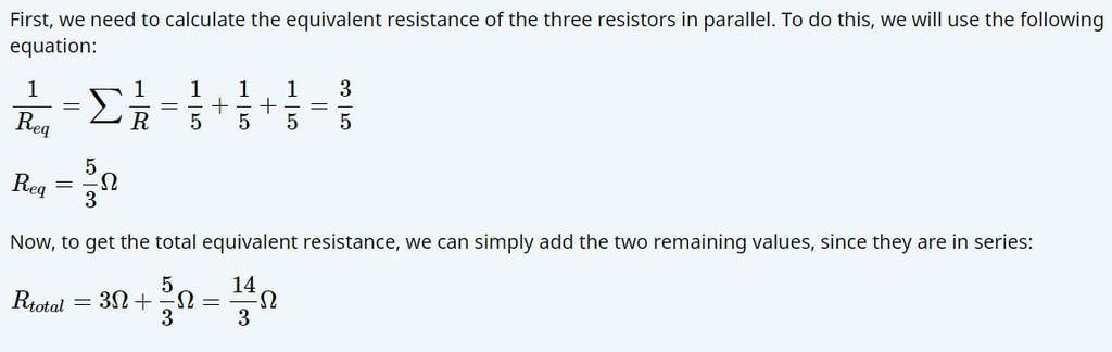
A circuit has a resistor with a resistance of 3Ω followed by three parallel branches, each holding a resistor with a resistance of 5Ω. What is the total equivalent resistance of the circuit?- a)15/3 Ω
- b)14/3 Ω
- c)15/7 Ω
- d)19/3 Ω
Correct answer is option 'B'. Can you explain this answer?
A circuit has a resistor with a resistance of 3Ω followed by three parallel branches, each holding a resistor with a resistance of 5Ω. What is the total equivalent resistance of the circuit?
a)
15/3 Ω
b)
14/3 Ω
c)
15/7 Ω
d)
19/3 Ω
|
|
Lavanya Menon answered |
Many resistors connected in series will?- a)Divide the voltage proportionally among all the resistors
- b)Divide the current proportionally
- c)Increase the source voltage in proportion to the values of the resistors
- d)Reduce the power to zero
Correct answer is option 'A'. Can you explain this answer?
Many resistors connected in series will?
a)
Divide the voltage proportionally among all the resistors
b)
Divide the current proportionally
c)
Increase the source voltage in proportion to the values of the resistors
d)
Reduce the power to zero
|
|
Mansi Datta answered |
In a series circuit, the current remains the same across all resistors hence the voltage divides proportionally among all resistors.
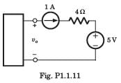
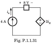
The voltage vo in fig. P1.1.11 is always equal to
- a)1 V
- b)5 V
- c)9 V
- d)None of the above
Correct answer is option 'D'. Can you explain this answer?
The voltage vo in fig. P1.1.11 is always equal to
a)
1 V
b)
5 V
c)
9 V
d)
None of the above
|
|
Sanvi Kapoor answered |
It is not possible to determine the voltage across 1 A source.
To neglect a voltage source, the terminal across the source are-- a)Open circuited
- b)Short circuited
- c)Replace by inductor
- d)Replace by some resistance
Correct answer is option 'B'. Can you explain this answer?
To neglect a voltage source, the terminal across the source are-
a)
Open circuited
b)
Short circuited
c)
Replace by inductor
d)
Replace by some resistance
|
|
Rahul Banerjee answered |
To neglect a voltage source, the terminals across the source should be short-circuited. Let's understand why this is the correct answer.
Short Circuit
A short circuit occurs when the terminals of a voltage source are connected directly without any resistance or impedance in between. This results in a very low resistance path for the current to flow, effectively bypassing the voltage source. In a short circuit, the voltage across the terminals is almost zero, which means the voltage source is neglected or ignored.
Open Circuit
An open circuit occurs when the terminals of a voltage source are not connected, creating an infinite resistance path. In an open circuit, no current flows, and the voltage across the terminals remains unchanged. Therefore, an open circuit cannot neglect a voltage source.
Replacement by Inductor
Replacing a voltage source with an inductor is not an appropriate method to neglect the source. An inductor resists changes in current flow, but it cannot completely bypass or ignore the voltage source. The inductor will still have an effect on the circuit, and the voltage across its terminals cannot be zero.
Replacement by Resistance
Similarly, replacing a voltage source with a resistance also cannot neglect the source. The resistance will still allow current to flow through it and will not completely bypass the voltage source. The voltage across the resistance will still be present, and the source cannot be neglected.
Conclusion
To neglect a voltage source, the terminals across the source should be short-circuited. This ensures that the voltage across the terminals is almost zero, effectively bypassing the source. Short-circuiting the terminals provides the best method to neglect a voltage source in a circuit.
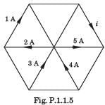
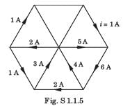
The currents entering in the three branches of a parallel circuit are 3A, 4A and 5A. What is the current leaving it?- a)0A
- b)Insufficient data provided
- c)The largest one among the three values
- d)12A
Correct answer is option 'D'. Can you explain this answer?
The currents entering in the three branches of a parallel circuit are 3A, 4A and 5A. What is the current leaving it?
a)
0A
b)
Insufficient data provided
c)
The largest one among the three values
d)
12A
|
|
Prisha Sengupta answered |
The total current leaving a node is the same as the current that enters it. Total I=I1+I2+I3=3+4+5=12A.
In which of the following elements, the voltage does not depend on either the value of the current flowing through the source or its direction?- a)Capacitor
- b)Resistor
- c)Independent Current source
- d)Independent Voltage source
Correct answer is option 'D'. Can you explain this answer?
In which of the following elements, the voltage does not depend on either the value of the current flowing through the source or its direction?
a)
Capacitor
b)
Resistor
c)
Independent Current source
d)
Independent Voltage source

|
EduRev GATE answered |
- An independent voltage source delivers a constant voltage regardless of the current flowing through it or the direction of the current.
- This characteristic means its voltage remains unchanged by external circuit elements or conditions.
- In contrast, a resistor and capacitor have voltages dependent on current and other factors like resistance or capacitance.
- An independent current source maintains a constant current, not voltage.
- Hence, the voltage of an independent voltage source (Option D) is unaffected by current variations.
Which one of the following must be ensured when two batteries are connected in parallel?- a)They should have the same make
- b)They should have the same emf
- c)They should have the same internal resistance
- d)They should have the same ampere-hour capacity
Correct answer is option 'B'. Can you explain this answer?
Which one of the following must be ensured when two batteries are connected in parallel?
a)
They should have the same make
b)
They should have the same emf
c)
They should have the same internal resistance
d)
They should have the same ampere-hour capacity
|
|
Zoya Sharma answered |
When batteries are connected in parallel it must be ensured that they have the same emf to avoid short circuits and to avoid any circulating current between batteries..
The Norton theorem reduces a circuit to which of the following circuits? - a)A current source only
- b)A current source with an impedance in parallel
- c)A current source with an impedance in series
- d)A voltage source only
Correct answer is option 'B'. Can you explain this answer?
The Norton theorem reduces a circuit to which of the following circuits?
a)
A current source only
b)
A current source with an impedance in parallel
c)
A current source with an impedance in series
d)
A voltage source only
|
|
Sakshi Roy answered |
Introduction:
The Norton theorem is a technique used in electrical engineering to simplify complex circuits by reducing them to an equivalent circuit. It is named after Edward Lawry Norton, who developed this theorem in 1926. The Norton theorem is useful for analyzing and solving circuit problems by representing a complex circuit as a simpler one.
The Norton Theorem:
The Norton theorem states that any linear circuit containing independent sources and resistors can be replaced by an equivalent circuit consisting of a current source in parallel with an impedance. The Norton equivalent circuit is useful for simplifying complex circuits and analyzing their behavior.
Equivalent Circuit:
The Norton equivalent circuit consists of a current source in parallel with an impedance. The current source represents the current flowing through the original circuit, while the impedance represents the total resistance seen by the current source.
Option Analysis:
Let's analyze the given options to determine which one correctly describes the Norton equivalent circuit.
a) A current source only:
This option is incorrect because the Norton equivalent circuit consists of a current source in parallel with an impedance. It is not a current source only.
b) A current source with an impedance in parallel:
This option is correct. The Norton equivalent circuit consists of a current source in parallel with an impedance. This combination accurately represents the behavior of the original circuit.
c) A current source with an impedance in series:
This option is incorrect. The Norton equivalent circuit does not consist of an impedance in series with the current source. It is in parallel.
d) A voltage source only:
This option is incorrect. The Norton equivalent circuit does not consist of a voltage source only. It is a current source in parallel with an impedance.
Conclusion:
The Norton theorem reduces a circuit to a current source with an impedance in parallel. This equivalent circuit accurately represents the behavior of the original circuit and simplifies its analysis. The Norton theorem is a powerful tool in electrical engineering and is widely used to solve complex circuit problems.
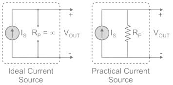
A practical current source consists of- a)An ideal current source in series with an impedance
- b)An ideal current source in parallel with an impedance
- c)An ideal current source with no impedance in series or in parallel
- d)An ideal current source with high impedance in series
Correct answer is option 'B'. Can you explain this answer?
A practical current source consists of
a)
An ideal current source in series with an impedance
b)
An ideal current source in parallel with an impedance
c)
An ideal current source with no impedance in series or in parallel
d)
An ideal current source with high impedance in series
|
|
EduRev GATE answered |
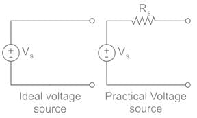
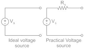
Ideal Voltage Source: An ideal voltage source has zero internal resistance.
Practical Voltage Source: A practical voltage source consists of an ideal voltage source (VS) in series with internal resistance (RS).
An ideal voltage source and a practical voltage source can be represented as shown in the figure.
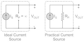
Ideal Current Source: An ideal voltage source has infinite resistance. Infinite resistance is equivalent to zero conductance. So, an ideal current source has zero conductance.
Ideal Current Source: An ideal voltage source has infinite resistance. Infinite resistance is equivalent to zero conductance. So, an ideal current source has zero conductance.
Practical Current Source: A practical current source is equivalent to an ideal current source in parallel with a high resistance or low conductance.
Ideal and practical current sources are represented as shown the below figure.
In which constant voltage system following operations are performed: - Measure the system current
- Compare it with a reference current
- Computes and amplifies the error signal
- a)Constant extinction angle δ control
- b)Constant voltage control
- c)Constant lignition angle β control
- d)Constant current control
Correct answer is option 'D'. Can you explain this answer?
In which constant voltage system following operations are performed:
- Measure the system current
- Compare it with a reference current
- Computes and amplifies the error signal
a)
Constant extinction angle δ control
b)
Constant voltage control
c)
Constant lignition angle β control
d)
Constant current control
|
|
Pallavi Nair answered |
B)Constant current control
If an ideal voltage source and ideal current source are connected in series, the combination- a)Has the same properties as a current source alone
- b)Has the same properties as a voltage source alone
- c)Has the some properties as the source which has a higher value
- d)Results in the branch being redundant
Correct answer is option 'A'. Can you explain this answer?
If an ideal voltage source and ideal current source are connected in series, the combination
a)
Has the same properties as a current source alone
b)
Has the same properties as a voltage source alone
c)
Has the some properties as the source which has a higher value
d)
Results in the branch being redundant
|
|
Ashwin Kapoor answered |
Explanation:
When an ideal voltage source and an ideal current source are connected in series, the combination has the same properties as a current source alone. This can be explained as follows:
1. Ideal voltage source:
An ideal voltage source is a two-terminal device that maintains a constant voltage across its terminals regardless of the current flowing through it. It is characterized by zero internal resistance and an infinite current capacity. In other words, it can supply any amount of current at a constant voltage.
2. Ideal current source:
An ideal current source is a two-terminal device that maintains a constant current through its terminals regardless of the voltage across it. It is characterized by zero internal resistance and an infinite voltage capacity. In other words, it can supply any voltage required to maintain the constant current.
3. Series connection:
When the ideal voltage source and the ideal current source are connected in series, the voltage across both devices is the same since they are connected in the same direction. However, the current flowing through both devices is different since they have different characteristics.
4. Combination properties:
The combination of an ideal voltage source and an ideal current source is equivalent to a current source alone since the current source maintains a constant current regardless of the voltage across it. The voltage across the combination is irrelevant since the current source will maintain the same current regardless of the voltage applied.
Conclusion:
Hence, the correct option is A, which states that the combination has the same properties as a current source alone.
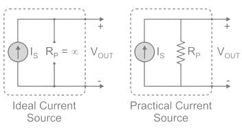
The ideal current source will have- a)high internal resistance
- b)zero internal resistance
- c)an infinite internal resistance
- d)low internal resistance
Correct answer is option 'C'. Can you explain this answer?
The ideal current source will have
a)
high internal resistance
b)
zero internal resistance
c)
an infinite internal resistance
d)
low internal resistance
|
|
Ritika Mukherjee answered |
The ideal current source is a theoretical concept in electrical engineering that can provide an unchanging, constant current to a circuit, regardless of the load. It is an important concept in circuit analysis and design, and it is often used to simplify complex circuits and calculations.
Internal resistance of an ideal current source
The internal resistance of an ideal current source is a key characteristic that determines its behavior and performance. The internal resistance of a current source is the resistance that is present within the source itself, which affects the current that can be delivered to the load.
Option (c) an infinite internal resistance is the correct answer for the following reasons:
- An ideal current source with zero internal resistance would be able to deliver an infinite amount of current, which is not physically possible.
- An ideal current source with high internal resistance would not be able to deliver enough current to the load, as the voltage drop across the internal resistance would reduce the output current.
- An ideal current source with low internal resistance would be able to deliver a high current, but it would be limited by the voltage supply and the load resistance.
Therefore, an ideal current source with an infinite internal resistance would be able to deliver a constant current to the load, regardless of the load resistance or voltage supply. This is because the internal resistance would not affect the output current, and it would remain constant.
Conclusion
In conclusion, an ideal current source with an infinite internal resistance is the most desirable characteristic for an ideal current source, as it provides a constant current to the load without being affected by the load resistance or voltage supply. However, it is important to note that an ideal current source is a theoretical concept and cannot be achieved in practice.
A non-ideal current source of 25 mA is supplying a resistive load of 5 kΩ. If the actual current flowing through the load is 20 mA, then the internal resistance of the source is:- a)1 kΩ
- b)10 kΩ
- c)5 kΩ
- d)20 kΩ
Correct answer is option 'D'. Can you explain this answer?
A non-ideal current source of 25 mA is supplying a resistive load of 5 kΩ. If the actual current flowing through the load is 20 mA, then the internal resistance of the source is:
a)
1 kΩ
b)
10 kΩ
c)
5 kΩ
d)
20 kΩ
|
|
Ravi Singh answered |
Concept:
Ideal Current Source: An ideal current source has infinite resistance. Infinite resistance is equivalent to zero conductance. So, an ideal current source has zero conductance.
Practical Current Source: A practical current source is equivalent to an ideal current source in parallel with high resistance or low conductance.
Ideal and practical current sources are represented as shown in the below figure.
Practical Current Source: A practical current source is equivalent to an ideal current source in parallel with high resistance or low conductance.
Ideal and practical current sources are represented as shown in the below figure.
Calculation:
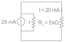
Resistive load RL = 5 × 10³ Ω
Current through load IL= 20 × 10-3 A
Internal resistance = r
Voltage across load, VL = RL × IL
= 5 × 103 × 20 × 10-3
= 100 V
The net current through internal resistance
r = 25 mA - 20 mA = 5 mA
Voltage across internal resistance = current × r
100 = 5 × 10⁻³ × r
r = 20 kΩ
Current through load IL= 20 × 10-3 A
Internal resistance = r
Voltage across load, VL = RL × IL
= 5 × 103 × 20 × 10-3
= 100 V
The net current through internal resistance
r = 25 mA - 20 mA = 5 mA
Voltage across internal resistance = current × r
100 = 5 × 10⁻³ × r
r = 20 kΩ
An ideal current source has- a)infinite source resistance
- b)zero source resistance
- c)large value of source resistance
- d)finite value of source resistance
Correct answer is option 'A'. Can you explain this answer?
An ideal current source has
a)
infinite source resistance
b)
zero source resistance
c)
large value of source resistance
d)
finite value of source resistance

|
Telecom Tuners answered |
Ideal current source: An ideal current source has infinite resistance. Infinite resistance is equivalent to zero conductance. So, an ideal current source has zero conductance.
Practical current source: A practical current source is equivalent to an ideal current source in parallel with high resistance or low conductance.
Ideal and practical current sources are represented as shown in the below figure:
Important Points
Important Points
Ideal voltage source: An ideal voltage source have zero internal resistance.
Practical voltage source: A practical voltage source consists of an ideal voltage source (VS) in series with internal resistance (RS) as follows.
An ideal voltage source and a practical voltage source can be represented as shown in the figure.
If n identical resistance, each of resistance R, are connected in parallel, the equivalent resistance is:- a)n2R
- b)R/n
- c)nR
- d)R/n2
Correct answer is option 'B'. Can you explain this answer?
If n identical resistance, each of resistance R, are connected in parallel, the equivalent resistance is:
a)
n2R
b)
R/n
c)
nR
d)
R/n2

|
Shivani Choudhury answered |
Understanding Parallel Resistance
When multiple identical resistors are connected in parallel, the total or equivalent resistance can be calculated using a specific formula. Let's break down the concept of parallel resistors to understand how the equivalent resistance is derived.
Equivalent Resistance Formula
For 'n' identical resistors, each with resistance R connected in parallel, the formula for equivalent resistance (Re) is:
1/Re = 1/R1 + 1/R2 + ... + 1/Rn
Since all resistors are identical:
1/Re = n/R
Steps to Calculate Equivalent Resistance
- Step 1: Identify the individual resistance (R) of each resistor.
- Step 2: Count the number of resistors (n).
- Step 3: Apply the formula:
1/Re = n/R
- Step 4: Rearranging gives:
Re = R/n
Conclusion
Thus, the equivalent resistance of 'n' identical resistors connected in parallel is R/n. This answer corresponds to option 'B', confirming that as more resistors are added in parallel, the overall resistance decreases, making it easier for current to flow through the circuit.
Key Takeaway
- For n identical resistors in parallel:
- Equivalent Resistance, Re = R/n
This principle is fundamental in electrical engineering and is widely used in circuit design to manage resistance and current flow effectively.
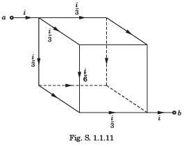
Twelve 6Ω resistor are used as edge to form a cube. The resistance between two diagonally opposite corner of the cube is- a)5/6 Ω
- b)6/5 Ω
- c)5 Ω
- d)6Ω
Correct answer is option 'C'. Can you explain this answer?
Twelve 6Ω resistor are used as edge to form a cube. The resistance between two diagonally opposite corner of the cube is
a)
5/6 Ω
b)
6/5 Ω
c)
5 Ω
d)
6Ω
|
|
Pallabi Pillai answered |
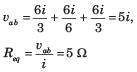
The current i will be distributed in the cube branches symmetrically
In a _________ circuit, the total resistance is greater than the largest resistance in the circuit.- a)Series
- b)Parallel
- c)Either series or parallel
- d)Neither series nor parallel
Correct answer is option 'A'. Can you explain this answer?
In a _________ circuit, the total resistance is greater than the largest resistance in the circuit.
a)
Series
b)
Parallel
c)
Either series or parallel
d)
Neither series nor parallel
|
|
Kritika Gupta answered |
In series circuits the total resistance is the sum of all the resistance in the circuit, hence the total is greater than the largest resistance.
Chapter doubts & questions for Circuit components - Electrical Engineering Optional Notes for UPSC 2025 is part of UPSC CSE exam preparation. The chapters have been prepared according to the UPSC CSE exam syllabus. The Chapter doubts & questions, notes, tests & MCQs are made for UPSC CSE 2025 Exam. Find important definitions, questions, notes, meanings, examples, exercises, MCQs and online tests here.
Chapter doubts & questions of Circuit components - Electrical Engineering Optional Notes for UPSC in English & Hindi are available as part of UPSC CSE exam.
Download more important topics, notes, lectures and mock test series for UPSC CSE Exam by signing up for free.
Electrical Engineering Optional Notes for UPSC
576 videos|646 docs|366 tests
|
|
© EduRev
|
Education Revolution
|


|


Signup on EduRev and stay on top of your study goals
10M+ students crushing their study goals daily