


All Exams >
Mechanical Engineering >
Mechanical Engineering SSC JE (Technical) >
All Questions
All questions of Design of Machine Elements for Mechanical Engineering Exam
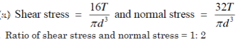

If a shaft made from ductile material is subjected to combined bending and twisting moment, calculations based on which one of the following failure theories will give the most conservative value?
a)Maximum shear stress theoryb)Maximum principal stress theoryc)Maximum strain energy theoryd)Maximum distortion energy theoryCorrect answer is option 'A'. Can you explain this answer?

|
Rahul Chatterjee answered |
If shaft made with the ductile material then they only follow Rankine Theory because it gives a satisfactory result for the shaft. As all knows guys Rankine theory also known as Maximum principal stress theory.
If the size of a standard specimen for a fatigue testing machine is increased, the endurance limit for the material will- a)have same value as that of standard specimen
- b)increases
- c)decreases
- d)none of these
Correct answer is option 'C'. Can you explain this answer?
If the size of a standard specimen for a fatigue testing machine is increased, the endurance limit for the material will
a)
have same value as that of standard specimen
b)
increases
c)
decreases
d)
none of these

|
Sagarika Patel answered |
In the diameter or size of the components is more the surface area will have greater number of surface defect. Hence endurance strength of component reduced with increase in size.
The design calculations for members subject to fluctuating loads with the same factor of safety yield the most conservative estimates when using
a)Gerber relationb)Goodman relationc)Soderberg relationd)None of the aboveCorrect answer is option 'C'. Can you explain this answer?
|
|
Aditya Deshmukh answered |
I.Soderberg criteria are used for ductile material and fluctuating loads.
II.Goodman criteria are used for brittle material and fluctuating loads.
When a nut is tightened by placing a washer below it the bolt will be subjected to- a)tensile stress
- b)compression stress
- c)shear stress
- d)none of these
Correct answer is option 'A'. Can you explain this answer?
When a nut is tightened by placing a washer below it the bolt will be subjected to
a)
tensile stress
b)
compression stress
c)
shear stress
d)
none of these
|
|
Zoya Sharma answered |
The answer is A: tensile stress.
When a nut is tightened by placing a washer below it, the bolt will be subjected to tensile stress. This means that the bolt will experience a stretching force along its length. Here is a detailed explanation:
1. Tensile stress:
- Tensile stress occurs when a force is applied to an object, causing it to stretch or elongate.
- In this case, when the nut is tightened, the washer applies a compressive force on the bolt, which in turn causes the bolt to stretch.
- The bolt is subjected to tensile stress because it experiences a force that tries to pull it apart along its length.
2. Compression stress:
- Compression stress occurs when a force is applied to an object, causing it to compress or shorten.
- In this scenario, the washer applies a compressive force on the bolt, but it does not cause the bolt to shorten or compress. Instead, it causes the bolt to stretch.
3. Shear stress:
- Shear stress occurs when a force is applied parallel to the surface of an object, causing it to deform or slide.
- In this case, the washer does not exert a force parallel to the surface of the bolt, so there is no shear stress involved.
4. None of these:
- The correct answer is not "none of these" because the bolt is indeed subjected to a type of stress, which is tensile stress.
In conclusion, when a nut is tightened by placing a washer below it, the bolt will be subjected to tensile stress as it experiences a force that tries to pull it apart along its length.
Removal of metal participles from the raceway of a rolling contact bearing is a kind of failure of bearing known as- a)pitting
- b)wearing
- c)spalling
- d)scuffing
Correct answer is option 'A'. Can you explain this answer?
Removal of metal participles from the raceway of a rolling contact bearing is a kind of failure of bearing known as
a)
pitting
b)
wearing
c)
spalling
d)
scuffing

|
Baishali Bajaj answered |
Pitting is a surface fatigue failure that occurs when load on the bearing exceeds the surface endurance strength. This is frequently found in ball bearing
Who postulated the maximum distortion energy theory?- a)Tresca
- b)Rankine
- c)St. Venant
- d)Mises-Henky
Correct answer is option 'D'. Can you explain this answer?
Who postulated the maximum distortion energy theory?
a)
Tresca
b)
Rankine
c)
St. Venant
d)
Mises-Henky
|
|
Avinash Mehta answered |
Mises – Henky Maximum shear strain energy theory → IES-15
In a journal bearings, the radius of the friction circle increases with the increase in- a)radius of the journal
- b)load
- c)speed of the journal
- d)viscosity of the lubricant
Correct answer is option 'A'. Can you explain this answer?
In a journal bearings, the radius of the friction circle increases with the increase in
a)
radius of the journal
b)
load
c)
speed of the journal
d)
viscosity of the lubricant
|
|
Anshul Sharma answered |
Radius of friction circle = μ×r
Where
μ= co efficient of friction
r = Radius of journal
For bolts of uniform strength, the shank diameter is made equal to- a)major diameter of threads
- b)pitch diameter of threads
- c)minor diameter of threads
- d)nominal diameter of threads
Correct answer is option 'A'. Can you explain this answer?
For bolts of uniform strength, the shank diameter is made equal to
a)
major diameter of threads
b)
pitch diameter of threads
c)
minor diameter of threads
d)
nominal diameter of threads
|
|
Sagarika Patel answered |
The correct answer is c.
Bolt of uniform strength are made by
Bolt of uniform strength are made by
1. Reducing the diameter of shank of bolt corresponding to that of minor diameter
2. Making a hole and making the area of shank equal to root area.
A transmission shaft subjected to bending loads must be designed on the basis of- a)maximum normal stress theory
- b)maximum shear stress theory
- c)maximum normal stress and maximum shear stress theories
- d)fatigue strength
Correct answer is option 'A'. Can you explain this answer?
A transmission shaft subjected to bending loads must be designed on the basis of
a)
maximum normal stress theory
b)
maximum shear stress theory
c)
maximum normal stress and maximum shear stress theories
d)
fatigue strength
|
|
Anjali Sengupta answered |
Correct Answer :- a
Explanation : Bending force is normal force, so that design based on maximum normal stress theory.
Which of the following property is affected by heat treatment?- a)Hardness
- b)Strength
- c)Ductility
- d)All of the mentioned
Correct answer is option 'D'. Can you explain this answer?
Which of the following property is affected by heat treatment?
a)
Hardness
b)
Strength
c)
Ductility
d)
All of the mentioned
|
|
Sanvi Kapoor answered |
Heat treatment involves changes in the micro structure and hence all the internal properties are effected.
In the assembly design of shaft, pulley and ke, the weakest member is- a)Pulley
- b)Key
- c)Shaft
- d)None
Correct answer is option 'B'. Can you explain this answer?
In the assembly design of shaft, pulley and ke, the weakest member is
a)
Pulley
b)
Key
c)
Shaft
d)
None

|
Dipika Nambiar answered |
In the assembly design of shaft, pulley, and key, the weakest member is the key (option B).
- Introduction:
In the assembly design of a shaft, pulley, and key, it is important to consider the strength and reliability of each component. The weakest member refers to the component that is most likely to fail or be damaged under the applied loads and operating conditions.
- Explanation:
1. Pulley: A pulley is a wheel with a grooved rim designed to transmit power and change the direction of a belt or cable. Pulleys are typically made of materials such as cast iron, steel, or aluminum. While pulleys can experience wear and tear over time, they are generally robust and able to withstand significant loads.
2. Shaft: The shaft is a long, cylindrical mechanical component that rotates and transmits power from one part of a machine to another. Shafts are commonly made of materials such as steel, stainless steel, or alloy steel. They are designed to withstand bending, torsional, and axial loads. Shafts are typically larger and stronger than pulleys and are less likely to fail under normal operating conditions.
3. Key: The key is a small, rectangular component that fits into a keyway on the shaft and pulley. It is used to transmit torque between the shaft and the pulley, preventing slippage under load. Keys are usually made of materials such as steel or stainless steel. However, compared to the shaft and pulley, the key is relatively small and susceptible to shear and bending stresses.
- Reasons for the key being the weakest member:
1. Size and geometry: The key is smaller and has a simpler geometry compared to the shaft and pulley. This means it has a lower cross-sectional area and reduced strength.
2. Load distribution: The key is responsible for transmitting torque between the shaft and pulley. It experiences concentrated stresses at the point of contact, leading to potential stress concentration and failure.
3. Weakest link: In an assembly, the strength of the entire system is determined by its weakest component. Since the key has lower strength compared to the shaft and pulley, it becomes the weakest link in the assembly.
- Conclusion:
In the assembly design of a shaft, pulley, and key, the key is the weakest member. This is due to its smaller size, simpler geometry, concentrated stresses, and lower strength compared to the shaft and pulley. Proper design considerations, material selection, and stress analysis are essential to ensure the reliability and longevity of the assembly.
For longitudinal joint in boiler, the type of joint used is- a)lap joint with one ring one slopping the other
- b)butt joint with single cover plate
- c)butt joint with double cover plate
- d)any one of the above
Correct answer is option 'C'. Can you explain this answer?
For longitudinal joint in boiler, the type of joint used is
a)
lap joint with one ring one slopping the other
b)
butt joint with single cover plate
c)
butt joint with double cover plate
d)
any one of the above
|
|
Sagarika Patel answered |
The longitudinal joint in a boiler shell is usually but with two cover plates. This joint is more efficient than lap joint. it is also stiffer and helps to maintain circularity of the shells.
In a single row deep groove ball bearing, cages are needed to- a)separate the two races
- b)separate the balls from inner race
- c)separate the outer race from the ball
- d)ensure that the balls do not cluster at one point and maintain proper relative angular portion
Correct answer is option 'D'. Can you explain this answer?
In a single row deep groove ball bearing, cages are needed to
a)
separate the two races
b)
separate the balls from inner race
c)
separate the outer race from the ball
d)
ensure that the balls do not cluster at one point and maintain proper relative angular portion

|
Abhay Kapoor answered |
Explanation:
A single row deep groove ball bearing consists of an inner race, an outer race, and a set of balls. Cages are used in these bearings to separate the balls from each other and maintain proper relative angular position. The following are the reasons why cages are needed in a single row deep groove ball bearing:
Prevent Ball Clustering:
If the balls are not separated properly, they may cluster at one point, resulting in increased friction and wear. The cages ensure that the balls are evenly spaced and do not cluster at one point.
Maintain Angular Position:
The cages ensure that the balls maintain proper relative angular position. This is important for the bearing to support axial and radial loads.
Prevent Contact:
The cages prevent the balls from contacting each other, which can cause damage to the bearing.
Separate Inner and Outer Races:
The cages also separate the inner and outer races, preventing metal-to-metal contact and reducing friction and wear.
Conclusion:
Cages are an important component of a single row deep groove ball bearing. They prevent ball clustering, maintain proper relative angular position, prevent contact between balls, and separate the inner and outer races.
The hemispherical end of a pressure vessel is fastened to the cylindrical portion of the pressure vessel with the help of gasket, bolts and lock nuts. The bolts are subjected to- a)tensile stress
- b)compressive stress
- c)shear stress
- d)bearing stress
Correct answer is option 'A'. Can you explain this answer?
The hemispherical end of a pressure vessel is fastened to the cylindrical portion of the pressure vessel with the help of gasket, bolts and lock nuts. The bolts are subjected to
a)
tensile stress
b)
compressive stress
c)
shear stress
d)
bearing stress

|
Ss V answered |
Remamber bolts are always subjected to tensile when it ll having a nut..nut Compressed the bolt than the bolt comes in tensile force only.
When a shaft transmits power through gears, the shaft experiences
- a)torsional stresses alone
- b)bending stresses alone
- c)varying bending and constant torsional stresses
- d)constant bending and varying torsional stresses
Correct answer is option 'D'. Can you explain this answer?
When a shaft transmits power through gears, the shaft experiences
a)
torsional stresses alone
b)
bending stresses alone
c)
varying bending and constant torsional stresses
d)
constant bending and varying torsional stresses
|
|
Mansi Rane answered |
Correct Answer :- D
Explanation : Bending stress due to fixing is constant but torsional stresses are varying since speed of shaft varies with the gear speed which is variable
Which one of the following loadings is considered for design of axles ?
- a) Bending moment only
- b) Twisting moment only
- c) Combined bending moment and torsion
- d) Combined action of bending moment, twisting moment and axial thrust
Correct answer is option 'A'. Can you explain this answer?
Which one of the following loadings is considered for design of axles ?
a)
Bending moment onlyb)
Twisting moment onlyc)
Combined bending moment and torsiond)
Combined action of bending moment, twisting moment and axial thrust|
|
Sanya Agarwal answered |
-A straight axle is a single rigid shaft connecting a wheel on the left side of the vehicle to a wheel on the right side. The axis of rotation fixed by the axle is common to both wheels. Such a design can keep the wheel positions steady under heavy stress, and can therefore support heavy loads.
-Bending moment is considered for design of axles.
Stress concentration in a machine component of ductile materials not so harmful as it is in brittle material because- a)In Ductile material local yielding may distribute stress concentration
- b)Ductile material have large Young's modulus
- c)Poisson's ratio is larger in ductile materials
- d)Modulus of rigidity is larger in ductile material
Correct answer is option 'A'. Can you explain this answer?
Stress concentration in a machine component of ductile materials not so harmful as it is in brittle material because
a)
In Ductile material local yielding may distribute stress concentration
b)
Ductile material have large Young's modulus
c)
Poisson's ratio is larger in ductile materials
d)
Modulus of rigidity is larger in ductile material

|
Shivam Sharma answered |
Stress concentration is more serious in brittle material because stress concentration in brittle material results in immediate failure while ductile materials neutralize effect of stress concentration to some extent by deforming plastically.
The maximum distortion energy theory of failure is suitable to predict the failure of which one of the following types of materials ?- a)Brittle materials
- b)Ductile materials
- c)Plastics
- d)Composite materials
Correct answer is option 'B'. Can you explain this answer?
The maximum distortion energy theory of failure is suitable to predict the failure of which one of the following types of materials ?
a)
Brittle materials
b)
Ductile materials
c)
Plastics
d)
Composite materials
|
|
Amrita Chauhan answered |
Maximum Distortion Energy Theory of Failure
The maximum distortion energy theory of failure is also known as the von Mises criterion. It is a theory used to predict the failure of materials under complex stress conditions. In this theory, the failure of a material occurs when the distortion energy exceeds the yield strength of the material.
Suitability of the Theory
The maximum distortion energy theory of failure is suitable for predicting the failure of ductile materials. Ductile materials are those materials that can undergo large plastic deformations before they fail. Examples of ductile materials include metals and alloys.
Explanation
When a ductile material is subjected to a complex stress state, the stress distribution can be decomposed into two components: hydrostatic stress and deviatoric stress. Hydrostatic stress is the pressure component of the stress and does not cause any deformation. Deviatoric stress is the shear component of the stress and causes deformation.
The maximum distortion energy theory of failure focuses on the deviatoric stress component. When the deviatoric stress component exceeds the yield strength of the material, plastic deformation occurs. The maximum distortion energy theory predicts failure when the distortion energy, which is a combination of the deviatoric stresses, exceeds the yield strength of the material.
In ductile materials, the maximum distortion energy theory of failure is more appropriate than other failure theories, such as the maximum principal stress theory and the maximum shear stress theory. This is because ductile materials can undergo large plastic deformations before they fail, which means that the stress distribution will change during deformation.
Conclusion
In summary, the maximum distortion energy theory of failure is suitable for predicting the failure of ductile materials. This theory is based on the deviatoric stress component and predicts failure when the distortion energy exceeds the yield strength of the material.
Disruptive strength is the maximum strength of a metal, when- a)subjected to 3 principal tensile stresses at right angles to one another and of equal magnitude
- b)loaded in tension
- c)loaded in compression
- d)loaded in shear
Correct answer is option 'A'. Can you explain this answer?
Disruptive strength is the maximum strength of a metal, when
a)
subjected to 3 principal tensile stresses at right angles to one another and of equal magnitude
b)
loaded in tension
c)
loaded in compression
d)
loaded in shear
|
|
Avantika Sen answered |
Disruptive strength in metals is the maximum strength a metal can withstand when subjected to three principal tensile stresses at right angles to each other and of equal magnitude. Let us understand the concept in detail.
Principal Stresses:
Principal stresses are the maximum and minimum normal stresses experienced by an element in a three-dimensional stress system. Every stress system has three principal stresses, which are perpendicular to each other.
Disruptive Strength:
The disruptive strength is the maximum strength or maximum normal stress a metal can withstand before it ruptures or fails. It is also known as the tensile strength of the material.
Three Principal Tensile Stresses at Right Angles:
When a metal is subjected to three principal tensile stresses that are at right angles to each other and of equal magnitude, it experiences the maximum normal stress, which is the disruptive strength of the material.
Loaded in Tension:
Tension is a type of stress that occurs when a material is pulled or stretched. When a metal is loaded in tension, it experiences normal stress, which is the force acting perpendicular to the surface area.
Loaded in Compression:
Compression is a type of stress that occurs when a material is pushed or squeezed. When a metal is loaded in compression, it experiences normal stress, which is the force acting perpendicular to the surface area.
Loaded in Shear:
Shear is a type of stress that occurs when a material is subjected to forces parallel to its surface. When a metal is loaded in shear, it experiences shear stress, which is the force acting parallel to the surface area.
Conclusion:
In summary, disruptive strength is the maximum strength a metal can withstand when subjected to three principal tensile stresses at right angles to each other and of equal magnitude. This concept is significant in mechanical engineering as it helps in designing machines and structures that can withstand maximum stress without rupturing or failing.
The bearing characteristic number in a hydrodynamic bearing depends on- a)it is closer to real life situation
- b)it leads to a safer design
- c)it leads to cost effective design
- d)no other assumption is possible
Correct answer is option 'C'. Can you explain this answer?
The bearing characteristic number in a hydrodynamic bearing depends on
a)
it is closer to real life situation
b)
it leads to a safer design
c)
it leads to cost effective design
d)
no other assumption is possible
|
|
Jyoti Choudhury answered |
Explanation:
A hydrodynamic bearing is a type of bearing that relies on a fluid film to support the rotating shaft. The bearing characteristic number, also known as the Sommerfeld number, is a dimensionless parameter that determines the performance of the hydrodynamic bearing. It is defined as the ratio of the viscous forces to the inertial forces in the fluid film.
The bearing characteristic number depends on several factors, including the dimensions of the bearing and the operating conditions. It is calculated using the following formula:
Bearing Characteristic Number = (Viscosity of the fluid) * (Shaft speed) * (Bearing length) / (Load on the bearing) * (Fluid film thickness)
Now, let's discuss why the correct answer is option C, which states that the bearing characteristic number in a hydrodynamic bearing depends on cost-effective design.
1. Cost-effective design:
- The bearing characteristic number plays a crucial role in determining the design parameters of the hydrodynamic bearing.
- By optimizing the bearing characteristic number, engineers can design a bearing that is cost-effective.
- A higher bearing characteristic number leads to a thinner fluid film, which reduces the amount of fluid required and hence, lowers the cost of the bearing.
- On the other hand, a lower bearing characteristic number requires a thicker fluid film, increasing the cost of the bearing.
2. Real-life situation:
- While it is true that the bearing characteristic number should be closer to real-life situations, this is not the most important factor in determining the bearing design.
- The bearing characteristic number is primarily used to determine the load-carrying capacity and stability of the hydrodynamic bearing.
- It ensures that the bearing can withstand the applied loads and operate reliably under normal operating conditions.
- While it is important to consider real-life situations, the primary focus is on the performance and safety of the bearing.
3. Safer design:
- While a higher bearing characteristic number may indicate a safer design in terms of load-carrying capacity, it does not necessarily guarantee overall safety.
- Other factors such as material selection, lubrication, and proper maintenance also contribute to the safety of the bearing.
- The bearing characteristic number is just one of many parameters that need to be considered in the design process.
4. No other assumption is possible:
- This statement is incorrect because the bearing characteristic number depends on various assumptions such as the fluid film being fully developed, laminar flow, and constant properties of the fluid.
- These assumptions are necessary to simplify the calculations and provide a reasonable estimate of the bearing performance.
In conclusion, the correct answer is option C because the bearing characteristic number in a hydrodynamic bearing plays a significant role in determining the cost-effective design. By optimizing this parameter, engineers can design a bearing that provides reliable performance while minimizing the cost of production.
A rotating shaft carrying a unidirectional transverse load is subjected to :- a)Variable bending stress
- b)Variable shear stress
- c)Constant bending stress
- d)Constant shear stress
Correct answer is option 'A'. Can you explain this answer?
A rotating shaft carrying a unidirectional transverse load is subjected to :
a)
Variable bending stress
b)
Variable shear stress
c)
Constant bending stress
d)
Constant shear stress
|
|
Atharva Majumdar answered |
Rotating Shaft Carrying a Unidirectional Transverse Load
Introduction:
When a rotating shaft carries a unidirectional transverse load, it experiences various stresses due to the bending and shearing actions. These stresses are not constant but vary along the length of the shaft.
Variable Bending Stress:
The bending stress in a rotating shaft with a unidirectional transverse load varies along its length. It is maximum at the point where the load is applied and gradually decreases towards the ends. This is because the bending moment is directly proportional to the distance from the load application point. Therefore, the bending stress is highest at the point of application and decreases as we move away from it.
Reason for Variable Bending Stress:
The bending stress is caused by the moment that is induced in the shaft due to the applied load. As the load is unidirectional, the moment varies along the length of the shaft. This results in variable bending stress distribution.
Constant Shear Stress:
Unlike bending stress, the shear stress in a rotating shaft carrying a unidirectional transverse load remains constant along its length. This is because shear stress is directly proportional to the applied load and inversely proportional to the shaft's cross-sectional area. Since both the load and the cross-sectional area remain constant along the length of the shaft, the shear stress also remains constant.
Uniform Shear Stress Distribution:
The shear stress is responsible for resisting the shearing action caused by the applied load. As the load is unidirectional, the shearing action remains constant along the length of the shaft. Therefore, the shear stress distribution is uniform throughout the shaft.
Conclusion:
In summary, when a rotating shaft carries a unidirectional transverse load, it experiences variable bending stress and constant shear stress. The bending stress varies along the length of the shaft, being highest at the point of load application and decreasing towards the ends. On the other hand, the shear stress remains constant along the shaft due to the uniform shearing action caused by the load.
For a cotter, the ratio of thickness to width is- a)1 : 4
- b)1 : 3
- c)2 : 3
- d)1 : 2
Correct answer is option 'A'. Can you explain this answer?
For a cotter, the ratio of thickness to width is
a)
1 : 4
b)
1 : 3
c)
2 : 3
d)
1 : 2
|
|
Lavanya Menon answered |
For a cotter, the ratio of thickness to width is. 1 : 4.
The bearing characteristic number in a hydrodynamic bearing depends upon- a)length, width and load
- b)Length, width and speed
- c)Viscosity, speed and load
- d)Viscosity, speed and bearing pressure
Correct answer is option 'D'. Can you explain this answer?
The bearing characteristic number in a hydrodynamic bearing depends upon
a)
length, width and load
b)
Length, width and speed
c)
Viscosity, speed and load
d)
Viscosity, speed and bearing pressure
|
|
Pritam Das answered |
Bearing Characteristic Number in Hydrodynamic Bearing
Bearing characteristic number is an important parameter used to determine the performance of a hydrodynamic bearing. It is defined as the ratio of the load-carrying capacity of the bearing to the viscous resistance developed in the bearing. The higher the value of the bearing characteristic number, the better the performance of the bearing.
Factors Affecting Bearing Characteristic Number
There are three main factors that affect the bearing characteristic number in a hydrodynamic bearing. They are:
1. Viscosity: The viscosity of the lubricant used in the bearing plays a crucial role in determining the bearing characteristic number. The higher the viscosity of the lubricant, the higher the bearing characteristic number.
2. Speed: The speed of the rotating shaft also affects the bearing characteristic number. The higher the speed, the lower the bearing characteristic number.
3. Bearing Pressure: The bearing pressure is the pressure exerted by the lubricant on the bearing surface. The higher the bearing pressure, the higher the bearing characteristic number.
Formula for Bearing Characteristic Number
The formula for calculating the bearing characteristic number is as follows:
C = W/ (π×L×V×P)
where,
C = Bearing characteristic number
W = Load-carrying capacity of the bearing
L = Length of the bearing
V = Viscosity of the lubricant
P = Bearing pressure
Conclusion
In conclusion, the bearing characteristic number in a hydrodynamic bearing depends on the viscosity of the lubricant, speed of the rotating shaft, and the bearing pressure. It is an important parameter that determines the performance of the bearing and can be calculated using the formula mentioned above.
The rivet head used for boiler plate riveting is usually- a)snap head
- b)pan head
- c)counter sink head
- d)conical head
Correct answer is option 'A'. Can you explain this answer?
The rivet head used for boiler plate riveting is usually
a)
snap head
b)
pan head
c)
counter sink head
d)
conical head
|
|
Sagnik Choudhary answered |
Rivet Head for Boiler Plate Riveting:
The rivet head used for boiler plate riveting is usually a snap head. Let's understand the reasons behind it.
What is Boiler Plate Riveting?
Boiler plate riveting is a process of joining two or more plates together using rivets. It is a widely used method for joining heavy-duty materials like steel plates used in boilers, ships, bridges, and other heavy structures.
Types of Rivet Heads:
There are various types of rivet heads available, including:
1. Snap Head
2. Pan Head
3. Countersink Head
4. Conical Head
Why Snap Head is Used for Boiler Plate Riveting?
The snap head is the most commonly used rivet head for boiler plate riveting. The reasons behind it are:
1. Strength: The snap head provides the maximum strength and stability to the joint. It is suitable for heavy-duty applications and can withstand high pressure and loads.
2. Flush Finish: The snap head provides a flush finish to the joint, making it suitable for applications where a smooth surface is required.
3. Easy to Install: The snap head is easy to install and does not require any special tool or equipment.
4. Cost-Effective: The snap head is cost-effective compared to other types of rivet heads.
Conclusion:
In summary, the snap head is the most suitable rivet head for boiler plate riveting due to its strength, flush finish, ease of installation, and cost-effectiveness.
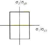
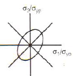
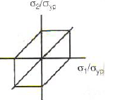
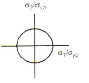
Match List-I (Failure theories) with List-II (Figures representing boundaries of these theories) and select the correct answer using the code given below the lists: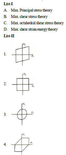
- a)A
- b)B
- c)C
- d)D
Correct answer is option 'D'. Can you explain this answer?
Match List-I (Failure theories) with List-II (Figures representing boundaries of these theories) and select the correct answer using the code given below the lists:
a)
A
b)
B
c)
C
d)
D

|
H C Rajpoot answered |
Maximum principal stress theory >>>>> Square
Maximum shear stress theory >>>>> Hexagon
Maximum octahedral shear stress theory >>>>> Rhombus
Maximum shear strain energy theory >>>>> Ellipse
In the welded joint shown in the given figure if the weld at B has thicker fillets than at A then load carrying capacity P0 of the joint will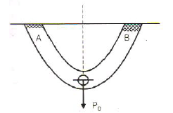
- a)increase
- b)decrease
- c)remain unaffected
- d)exactly get doubled
Correct answer is option 'C'. Can you explain this answer?
In the welded joint shown in the given figure if the weld at B has thicker fillets than at A then load carrying capacity P0 of the joint will
a)
increase
b)
decrease
c)
remain unaffected
d)
exactly get doubled

|
Mrinalini Sen answered |
Load carrying capacity doesn't depends upon the thickness of weld
For bolts of uniform strength, the shank diameter is made equal to- a)major diameter of threads
- b)pitch diameter of threads
- c)minor diameter of threads
- d)nominal diameter of threads
Correct answer is option 'C'. Can you explain this answer?
For bolts of uniform strength, the shank diameter is made equal to
a)
major diameter of threads
b)
pitch diameter of threads
c)
minor diameter of threads
d)
nominal diameter of threads
|
|
Siddharth Menon answered |
Shank Diameter for Bolts of Uniform Strength:
In bolts of uniform strength, the shank diameter is made equal to the minor diameter of threads. Let's understand this in detail.
Uniform Strength Bolts:
Uniform strength bolts are designed to have the same strength in the shank as in the threaded portion of the bolt. This is achieved by reducing the cross-sectional area of the threaded portion of the bolt so that it matches the cross-sectional area of the shank. This ensures that the bolt will fail in the shank section rather than in the threaded section.
Minor Diameter of Threads:
The minor diameter of threads is the smallest diameter of the threaded section of the bolt. It is the diameter of the imaginary cylinder that passes through the bottom of the threads. The minor diameter is used to calculate the tensile strength of the bolt.
Relation between Shank Diameter and Minor Diameter of Threads:
In bolts of uniform strength, the shank diameter is made equal to the minor diameter of threads. This is done to ensure that the bolt has the same strength in the shank and threaded portions. If the shank diameter is larger than the minor diameter of threads, then the bolt will have more strength in the shank than in the threaded portion. This will cause the bolt to fail in the threaded portion rather than the shank. On the other hand, if the shank diameter is smaller than the minor diameter of threads, then the bolt will have more strength in the threaded portion than in the shank. This will cause the bolt to fail in the shank portion rather than the threaded portion.
Conclusion:
In conclusion, the shank diameter for bolts of uniform strength is made equal to the minor diameter of threads to ensure that the bolt has the same strength in the shank and threaded portions.
The piston rod and the crosshead in a steam engine are usually connected by means of- a)Cotter joint
- b)Knuckle joint
- c)Ball joint
- d)Universal joint
Correct answer is option 'A'. Can you explain this answer?
The piston rod and the crosshead in a steam engine are usually connected by means of
a)
Cotter joint
b)
Knuckle joint
c)
Ball joint
d)
Universal joint
|
|
Aniket Saini answered |
Piston Rod and Crosshead Connection in Steam Engine
The piston rod and the crosshead in a steam engine are two crucial components that enable the reciprocating motion of the piston to be converted into a linear motion. There are different types of joints that can be used to connect the piston rod and the crosshead, including cotter joint, knuckle joint, ball joint, and universal joint. The correct answer to this question is option 'A', which is cotter joint. In this joint, the two components are connected by means of a wedge-shaped piece of metal called a cotter.
What is a Cotter Joint?
A cotter joint is a type of mechanical joint that is used to connect two rods or bars of equal diameter. The joint consists of a tapered pin or wedge-shaped piece of metal called a cotter, which is driven into a slot or keyway in the two components to be joined. The cotter is secured in place by means of a nut or bolt, which is tightened to apply pressure on the joint and prevent it from slipping or coming apart.
Advantages of Cotter Joint
1. Simple and easy to manufacture
2. Provides a strong and rigid connection between the two components
3. Can be easily disassembled for maintenance or repair
4. Can be used for both tension and compression loads
5. Economical
Disadvantages of Cotter Joint
1. The joint is not suitable for connecting two components of different diameter
2. The cotter can be subjected to shear stress, which can cause it to break
3. The joint requires a precise fit between the cotter and the slot, which can be time-consuming to achieve
Conclusion
In conclusion, the piston rod and the crosshead in a steam engine are usually connected by means of a cotter joint. This joint provides a simple, strong, and economical connection that can be easily disassembled for maintenance or repair. However, it is important to ensure that the joint is properly designed and manufactured to prevent failure due to shear stress or poor fit.
The bolts in a rigid flanged coupling connecting two shafts transmitting power are subjected to- a)shear force and bending moment
- b)axial force
- c)torsion and bending moment
- d)torsion
Correct answer is option 'A'. Can you explain this answer?
The bolts in a rigid flanged coupling connecting two shafts transmitting power are subjected to
a)
shear force and bending moment
b)
axial force
c)
torsion and bending moment
d)
torsion
|
|
Sinjini Bose answered |
Answer:
The bolts in a rigid flanged coupling connecting two shafts transmitting power are subjected to shear force and bending moment. This can be explained as follows:
Shear force:
When two shafts are transmitting power, they are subjected to forces that tend to move them in opposite directions. This causes a shear force to act on the bolts of the flanged coupling that connects the two shafts. The shear force is a transverse force that acts perpendicular to the longitudinal axis of the bolt.
Bending moment:
Apart from the shear force, the bolts in a flanged coupling are also subjected to a bending moment. This happens because the flanges on both sides of the coupling are rigidly connected to the shafts. When the shafts are subjected to torque, the flanges also rotate. This causes a bending moment to act on the bolts that connect the flanges to the shafts. The bending moment is a force that tends to bend the bolt about its longitudinal axis.
Conclusion:
Hence, due to the combined action of shear force and bending moment, the bolts in a rigid flanged coupling connecting two shafts transmitting power are subjected to high stresses. It is important to ensure that the bolts are designed to withstand these stresses to avoid failure of the coupling.
The factor of safety for steel and for steady load is- a)2
- b)4
- c)6
- d)8
Correct answer is option 'B'. Can you explain this answer?
The factor of safety for steel and for steady load is
a)
2
b)
4
c)
6
d)
8
|
|
Divyansh Goyal answered |
Factor of Safety for Steel and Steady Load
Factors of safety are used in engineering to provide a margin of safety for design calculations. It is defined as the ratio between the maximum stress a material can withstand and the actual stress it is subjected to.
Steel
- Steel is a commonly used material in engineering due to its high strength and durability.
- The factor of safety for steel is usually determined based on the type of load and the application.
Steady Load
- Steady load refers to a constant or unchanging load applied to a structure or material.
- The factor of safety for steady load ensures that the material can withstand the load over an extended period without failure.
Factor of Safety Calculation
- The factor of safety for steel and steady load is typically around 4.
- This means that the material is designed to withstand four times the maximum stress it is expected to experience under steady load conditions.
Therefore, the correct answer is option B, which is 4. This factor of safety provides a reasonable margin to account for uncertainties in material properties, variations in load conditions, and potential safety hazards.
The thickness of cotter is generally taken equal to- a)0.15 d
- b)0.3 d
- c)0.4 d
- d)0.5 d
Correct answer is option 'B'. Can you explain this answer?
The thickness of cotter is generally taken equal to
a)
0.15 d
b)
0.3 d
c)
0.4 d
d)
0.5 d

|
Bhaskar Unni answered |
Explanation:
Thickness of Cotter:
- The thickness of a cotter is generally taken equal to 0.3 times the diameter of the shaft (d).
- This means the thickness of the cotter (t) is given by t = 0.3d.
Reasoning:
- The thickness of the cotter is chosen to provide enough strength to withstand the forces acting on it during operation.
- A thickness of 0.3 times the shaft diameter is considered adequate to ensure the cotter can effectively transfer the load without failing.
Significance:
- Choosing the appropriate thickness for the cotter is crucial to ensure the proper functioning of the mechanical system.
- The correct thickness helps prevent issues such as slippage, wear, or failure of the cotter, which could lead to malfunction of the machine.
Therefore, in mechanical engineering applications, the thickness of a cotter is generally taken as 0.3 times the diameter of the shaft to ensure optimal performance and reliability.
In the design of connecting rod small end bearing, the value of permissible bearing pressure to be used is :- a)Less than that used for big end bearing
- b)More than that used for big end bearing
- c)Equal to that used for big end bearing
- d)None of the above
Correct answer is option 'B'. Can you explain this answer?
In the design of connecting rod small end bearing, the value of permissible bearing pressure to be used is :
a)
Less than that used for big end bearing
b)
More than that used for big end bearing
c)
Equal to that used for big end bearing
d)
None of the above
|
|
Akshat Mehta answered |
Permissible Bearing Pressure in Connecting Rod Small End Bearing
In the design of a connecting rod, both the big end bearing and the small end bearing play a critical role in transferring the axial and radial loads generated during the engine operation. The small end bearing is located at the small end of the connecting rod and is responsible for supporting the piston pin or wrist pin.
Difference between Big End Bearing and Small End Bearing
The big end bearing is subjected to higher loads compared to the small end bearing due to its position closer to the crankshaft. The big end bearing supports the crankpin, which experiences higher forces and moments during engine operation. Therefore, it is designed to withstand higher bearing pressures.
The small end bearing, on the other hand, supports the lighter piston pin and experiences relatively lower loads compared to the big end bearing. The piston pin connects the connecting rod to the piston and is responsible for transmitting the reciprocating motion of the piston to the connecting rod. As the load on the small end bearing is lower, it does not require the same level of strength as the big end bearing.
Permissible Bearing Pressure
The permissible bearing pressure is the maximum pressure that the bearing material can withstand without excessive wear or failure. It is determined based on factors such as the material properties, lubrication conditions, and design considerations.
In the case of a connecting rod, the permissible bearing pressure for the small end bearing is generally higher than that used for the big end bearing. This is because the small end bearing operates under lower loads and experiences less severe conditions compared to the big end bearing. Using a higher permissible bearing pressure for the small end bearing allows for a more compact and lightweight design without compromising the overall performance and reliability of the connecting rod assembly.
Therefore, the correct answer to the given question is option 'B' - the permissible bearing pressure to be used in the design of the connecting rod small end bearing is more than that used for the big end bearing.
In conclusion, the small end bearing in a connecting rod is subjected to lower loads and operates under less severe conditions compared to the big end bearing. Hence, a higher permissible bearing pressure is used for the small end bearing, allowing for a more compact and lightweight design without compromising the overall performance and reliability of the connecting rod assembly.
Tapered roller bearings can take- a)radial load only
- b)axial load only
- c)both radial and axial load and the ratio of these being less than unity
- d)both radial and axial load and the ratio of these being greater than unity
Correct answer is option 'D'. Can you explain this answer?
Tapered roller bearings can take
a)
radial load only
b)
axial load only
c)
both radial and axial load and the ratio of these being less than unity
d)
both radial and axial load and the ratio of these being greater than unity
|
|
Yash Das answered |
Tapered roller bearings can take both radial and axial loads, and the ratio of these being greater than unity.
Explanation:
Tapered roller bearings are a type of rolling-element bearing used in heavy-duty applications, such as automotive, machine tool, and industrial machinery. These bearings consist of inner and outer rings, as well as tapered rollers that are assembled between them. The angle of the tapered rollers enables them to support both radial and axial loads.
Radial Load:
Radial load is a force that acts perpendicular to the axis of rotation. Tapered roller bearings can support radial loads due to the contact between the rollers and the raceways of the inner and outer rings. The tapered shape of the rollers helps to distribute the load evenly across the bearing surface, which reduces the stress on individual components.
Axial Load:
Axial load is a force that acts parallel to the axis of rotation. Tapered roller bearings can also support axial loads due to the contact angle between the rollers and the raceways. The angle of the tapered rollers enables them to transmit force in a specific direction, which helps to resist the thrust caused by the axial load.
Ratio of Radial and Axial Load:
The ratio of radial and axial load is an important consideration when selecting tapered roller bearings. If the ratio is less than unity, the bearing is better suited for radial loads. If the ratio is greater than unity, the bearing is better suited for axial loads. Tapered roller bearings are designed to handle both types of loads, but their performance may be optimized for one type of load over the other.
Conclusion:
In conclusion, tapered roller bearings can support both radial and axial loads, and the ratio of these being greater than unity. This makes them a versatile and reliable option for heavy-duty applications that require high load capacity and durability.
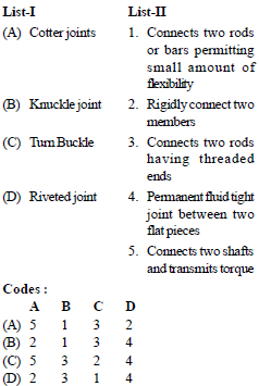
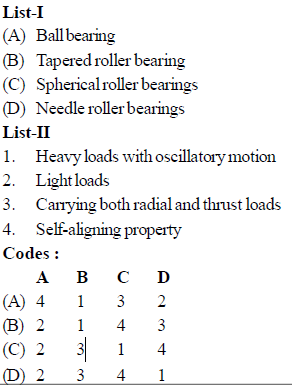
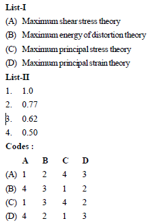
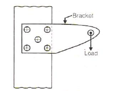


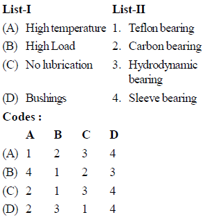
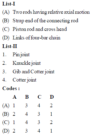
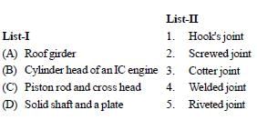
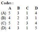
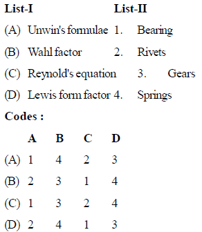
Chapter doubts & questions for Design of Machine Elements - Mechanical Engineering SSC JE (Technical) 2025 is part of Mechanical Engineering exam preparation. The chapters have been prepared according to the Mechanical Engineering exam syllabus. The Chapter doubts & questions, notes, tests & MCQs are made for Mechanical Engineering 2025 Exam. Find important definitions, questions, notes, meanings, examples, exercises, MCQs and online tests here.
Chapter doubts & questions of Design of Machine Elements - Mechanical Engineering SSC JE (Technical) in English & Hindi are available as part of Mechanical Engineering exam.
Download more important topics, notes, lectures and mock test series for Mechanical Engineering Exam by signing up for free.
Mechanical Engineering SSC JE (Technical)
6 videos|104 docs|59 tests
|
|
© EduRev
|
Education Revolution
|


|


Signup to see your scores
go up
within 7 days!
within 7 days!
Takes less than 10 seconds to signup