


All Exams >
GATE Physics >
Electronics for GATE >
All Questions
All questions of Digital Electronics for GATE Physics Exam
Most demultiplexers facilitate which type of conversion? - a)Single input, multiple outputs
- b)Decimal-to-hexadecimal
- c)AC to DC
- d)Odd parity to even parity
Correct answer is option 'A'. Can you explain this answer?
Most demultiplexers facilitate which type of conversion?
a)
Single input, multiple outputs
b)
Decimal-to-hexadecimal
c)
AC to DC
d)
Odd parity to even parity
|
|
Vedika Singh answered |
A demultiplexer sends a single input to multiple outputs, depending on the select lines. Demultiplexer converts single input into multiple outputs.

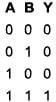
The truth table for the input NAND gate is given by :

|
Niharika Choudhary answered |
NAND gate is given as 
The correct answer is:
The correct answer is:
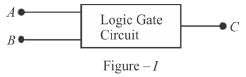
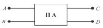
Figure-I shows a logic circuit with two inputs A and B and output C. The voltage incorrect waveform of A, B and C are shown in figure-II. The logic circuit is :
- a)NOR gate
- b)OR gate
- c)NAND gate
- d)AND gate
Correct answer is option 'D'. Can you explain this answer?
Figure-I shows a logic circuit with two inputs A and B and output C. The voltage incorrect waveform of A, B and C are shown in figure-II. The logic circuit is :
a)
NOR gate
b)
OR gate
c)
NAND gate
d)
AND gate
|
|
Priya Saha answered |
From the waveform A, B and C, it is clear that output is 1, if both B and A are 1 otherwise zero.
C = A . B
The correct answer is: AND gate
C = A . B
The correct answer is: AND gate
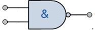
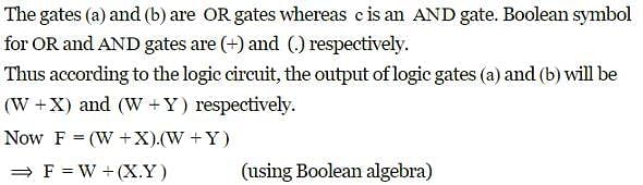
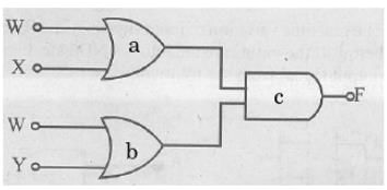
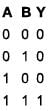
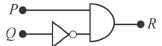
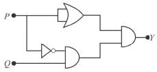
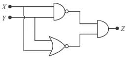
What will be the output of the logic gate formed by the circuit drawn below for inputs 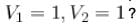
Correct answer is '0'. Can you explain this answer?
What will be the output of the logic gate formed by the circuit drawn below for inputs
|
|
Vedika Singh answered |
The above figure behaves as a NAND gate, hence for 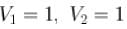 and output = 0
The correct answer is: 0
and output = 0The correct answer is: 0
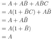
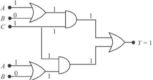
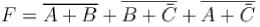
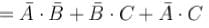
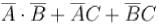
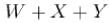
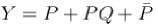
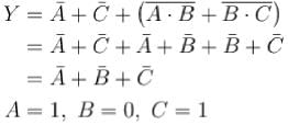
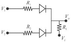
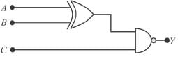
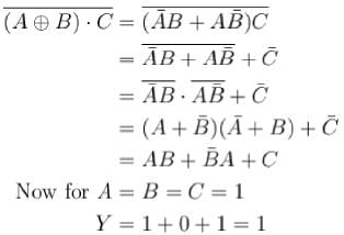
For the Boolean expression 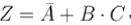 what will output for A= 1, B = 1, C = 0 ?
Correct answer is '0'. Can you explain this answer?
For the Boolean expression what will output for A= 1, B = 1, C = 0 ?
what will output for A= 1, B = 1, C = 0 ?|
|
Jayant Mishra answered |
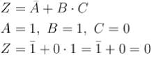
The correct answer is: 0
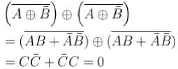
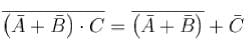
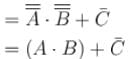
The minimum number of NAND gates required to implement 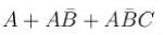 ?
?
Correct answer is '0'. Can you explain this answer?
The minimum number of NAND gates required to implement ?
?|
|
Vedika Singh answered |
Hence, minimum number of NAND gates required to implement
 is zero.
The correct answer is: 0
How many entries will be in the truth table of a 4-input NAND gate?- a)6
- b)8
- c)16
- d)32
Correct answer is option 'C'. Can you explain this answer?
How many entries will be in the truth table of a 4-input NAND gate?
a)
6
b)
8
c)
16
d)
32
|
|
Pooja Choudhury answered |
A NAND gate is a universal logic gate that performs the negation (NOT) of an AND logic operations in digital circuits.
As we know,
Y = 2n
Y number of Entries in the truth table Where, n = number of inputs.
As we know,
Y = 2n
Y number of Entries in the truth table Where, n = number of inputs.
When an input electrical signal A = 10100 is applied to a NOT gate, its output signal is :- a)10100
- b)10101
- c)01011
- d)00101
Correct answer is option 'C'. Can you explain this answer?
When an input electrical signal A = 10100 is applied to a NOT gate, its output signal is :
a)
10100
b)
10101
c)
01011
d)
00101
|
|
Niharika Choudhary answered |
NOT gate implies output  where A is the input.
The correct answer is: 01011
where A is the input.The correct answer is: 01011
If the output of a logic gate is 0 only when all its inputs are at logic 1, then which of the following are/is not the corresponding gate?
- a)AND
- b)NAND
- c)NOR
- d)NOT
Correct answer is option 'A,C,D'. Can you explain this answer?
If the output of a logic gate is 0 only when all its inputs are at logic 1, then which of the following are/is not the corresponding gate?
a)
AND
b)
NAND
c)
NOR
d)
NOT
|
|
Aditi Basak answered |
Truth table is,
This is truth table for NAND gate.
This is truth table for NAND gate.
The gate whose output is low if and only if all inputs are high, is NAND.
The logic NAND gate is a combination of a digital logic AND gate and a NOT gate connected together in series.
A NAND gate (NOT-AND) is a logic gate which produces an output which is false only if all its inputs are true; thus its output is complement to that of an AND gate. A LOW (0) output results only if all the inputs to the gate are HIGH (1); if any input is LOW (0), a HIGH (1) output results.
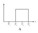
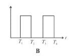
A pulse is applied to each input of an exclusive OR gate. One pulse goes HIGH at t = 0 and goes back LOW at t = 1 ms. The other pulse goes HIGH at t = 0.8 ms and goes back LOW at t = 3 ms. The output pulse can be described as follows :- a)It goes HIGH at t = 0 and back LOW at t = 3 ms
- b)It goes HIGH at t = 0 and back LOW at t = 1 ms
- c)It goes HIGH at t = 0 and back LOW at t = 0.8 ms
- d)It goes HIGH at t = 1 ms and back LOW at t = 3 ms
Correct answer is option 'C,D'. Can you explain this answer?
A pulse is applied to each input of an exclusive OR gate. One pulse goes HIGH at t = 0 and goes back LOW at t = 1 ms. The other pulse goes HIGH at t = 0.8 ms and goes back LOW at t = 3 ms. The output pulse can be described as follows :
a)
It goes HIGH at t = 0 and back LOW at t = 3 ms
b)
It goes HIGH at t = 0 and back LOW at t = 1 ms
c)
It goes HIGH at t = 0 and back LOW at t = 0.8 ms
d)
It goes HIGH at t = 1 ms and back LOW at t = 3 ms

|
Amar Chawla answered |
Output is HIGH when only one of the input is high.
The correct answers are: It goes HIGH at t = 0 and back LOW at t = 0.8 ms, It goes HIGH at t = 1 ms and back LOW at t = 3 ms
The correct answers are: It goes HIGH at t = 0 and back LOW at t = 0.8 ms, It goes HIGH at t = 1 ms and back LOW at t = 3 ms
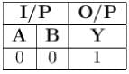
If two input terminals of NAND gate are shorted, then the output for both the input being zero is ?
Correct answer is '1'. Can you explain this answer?
If two input terminals of NAND gate are shorted, then the output for both the input being zero is ?
|
|
Utkarsh Shukla answered |
Explanation:
When the two input terminals of a NAND gate are shorted, it means that both inputs are connected together. Let's analyze the behavior of a NAND gate under this condition.
Truth Table of NAND Gate:
A NAND gate is a logic gate that produces an output of 0 only when all of its inputs are 1. Otherwise, the output is always 1.
| A | B | Output |
|---|---|--------|
| 0 | 0 | 1 |
| 0 | 1 | 1 |
| 1 | 0 | 1 |
| 1 | 1 | 0 |
Case 1: Both Inputs are 0:
When both input terminals of a NAND gate are shorted and set to 0, it means that the same 0 voltage is applied to both inputs simultaneously. According to the truth table, when both inputs are 0, the output is 1.
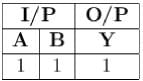
Case 2: One or Both Inputs are 1:
In this case, at least one of the inputs is 1. According to the truth table, when any input is 1, the output of the NAND gate will always be 0.
Therefore, when both input terminals of a NAND gate are shorted, the output will be 1 only when both inputs are 0. In all other cases, when one or both inputs are 1, the output will be 0.
Summary:
- When both inputs of a NAND gate are shorted, the output is 1 only when both inputs are 0.
- If one or both inputs are 1, the output of a NAND gate will always be 0, regardless of whether the inputs are shorted or not.
When the two input terminals of a NAND gate are shorted, it means that both inputs are connected together. Let's analyze the behavior of a NAND gate under this condition.
Truth Table of NAND Gate:
A NAND gate is a logic gate that produces an output of 0 only when all of its inputs are 1. Otherwise, the output is always 1.
| A | B | Output |
|---|---|--------|
| 0 | 0 | 1 |
| 0 | 1 | 1 |
| 1 | 0 | 1 |
| 1 | 1 | 0 |
Case 1: Both Inputs are 0:
When both input terminals of a NAND gate are shorted and set to 0, it means that the same 0 voltage is applied to both inputs simultaneously. According to the truth table, when both inputs are 0, the output is 1.
Case 2: One or Both Inputs are 1:
In this case, at least one of the inputs is 1. According to the truth table, when any input is 1, the output of the NAND gate will always be 0.
Therefore, when both input terminals of a NAND gate are shorted, the output will be 1 only when both inputs are 0. In all other cases, when one or both inputs are 1, the output will be 0.
Summary:
- When both inputs of a NAND gate are shorted, the output is 1 only when both inputs are 0.
- If one or both inputs are 1, the output of a NAND gate will always be 0, regardless of whether the inputs are shorted or not.
The binary number 110000111101 corresponds to a hexadecimal number. - a)CFD
- b)DBF
- c)D3C
- d)C3D
Correct answer is option 'D'. Can you explain this answer?
The binary number 110000111101 corresponds to a hexadecimal number.
a)
CFD
b)
DBF
c)
D3C
d)
C3D
|
|
Bhavana Pillai answered |
Hexadecimal is written with 16 numbers starting from 0, i.e., 0, 1,2, 3,...14, 15. The number 10 → A; 11 → B; 12 → C; 13 → D; 14 → E; 15 → F in place of two digits. To convert binary number in hexadecimal make the pairs of four numbers starting from right. Then convert them in decimal then hexadecimal e.g. (110000111101)2 ⇔ [(1100) (0011) (1101)2] in binary number ⇔ [(12) (3) (13) ] in decimal
= C3D is the equivalent hexadecimal number
The correct answer is: C3D
= C3D is the equivalent hexadecimal number
The correct answer is: C3D
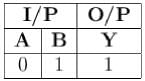
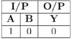
Inputs given to a logic gate are A and B and its output is X. If A = 1, B = 0, then X = 1. What type of gate this could be?- a)OR
- b)NAND
- c)AND
- d)NOR
Correct answer is option 'A,B'. Can you explain this answer?
Inputs given to a logic gate are A and B and its output is X. If A = 1, B = 0, then X = 1. What type of gate this could be?
a)
OR
b)
NAND
c)
AND
d)
NOR
|
|
Vaibhav Ghosh answered |
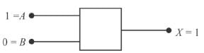
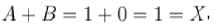 clearly it follows OR gate.
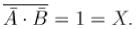
Thus, it also follows NAND gate
 it is an AND gate
 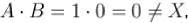 it is not a NOR gate.
 Therefore, the correct options are (b, c)
The correct answers are: NAND, OR
A pulse is applied to each input of a 2 input NAND gate, one pulse goes high at t = 0 and goes back LOW at t = 1 ms. The other pulse goes high at f = 0.8 ms and goes Mark 0.00 out of 2.00 back LOW at t = 3 ms. The output pulse.- a)comes back high at t = 1 ms
- b)comes back high at t = 3 ms
- c)goes low at t = 0.8 ms
- d)goes low at t = 0
Correct answer is option 'A,C'. Can you explain this answer?
A pulse is applied to each input of a 2 input NAND gate, one pulse goes high at t = 0 and goes back LOW at t = 1 ms. The other pulse goes high at f = 0.8 ms and goes Mark 0.00 out of 2.00 back LOW at t = 3 ms. The output pulse.
a)
comes back high at t = 1 ms
b)
comes back high at t = 3 ms
c)
goes low at t = 0.8 ms
d)
goes low at t = 0
|
|
Pranavi Mishra answered |
A NAND gate is given by  Truth table is.
It is low when both input signals are high otherwise it goes high.
The correct answers are: goes low at t = 0.8 ms, comes back high at t = 1 ms
Truth table is.It is low when both input signals are high otherwise it goes high.
The correct answers are: goes low at t = 0.8 ms, comes back high at t = 1 ms
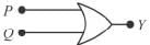
When both the input signals A and B of the NOR & NAND gate are connected together, The output of the resultant circuit will be equivalent to (Write all letter in Captial without any space and Just write Gate Name like NOR, NOT,XOR)
Correct answer is 'NOT'. Can you explain this answer?
When both the input signals A and B of the NOR & NAND gate are connected together, The output of the resultant circuit will be equivalent to (Write all letter in Captial without any space and Just write Gate Name like NOR, NOT,XOR)
|
|
Priya Saha answered |
When both the input signals A and B of NOR & NAND gate are connected together, we have one common input connection hence the resultant output will be NOT gated.
If the memory chip size is 256 x 1 bits, what is the number of chips required to make 1 up 1K byte of memory
Correct answer is '32'. Can you explain this answer?
If the memory chip size is 256 x 1 bits, what is the number of chips required to make 1 up 1K byte of memory
|
|
Niharika Kulkarni answered |
1 byte = 8 bits
1K byte = 1024 bits
1K byte = 1024 x 8 bit
Number of chips =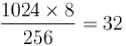
The correct answer is: 32
1K byte = 1024 bits
1K byte = 1024 x 8 bit
Number of chips =
The correct answer is: 32
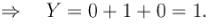
What must be the output if A = 1 , B = 0, C = 1 ?
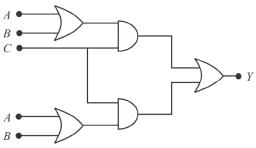
Correct answer is '1'. Can you explain this answer?
What must be the output if A = 1 , B = 0, C = 1 ?
|
|
Vandana Gupta answered |
 Hence, output = 1
The correct answer is: 1
The number 6.25 in the decimal notation, when converted to the binary notation will read as ?
Correct answer is '110.01'. Can you explain this answer?
The number 6.25 in the decimal notation, when converted to the binary notation will read as ?
|
|
Aashna Shah answered |
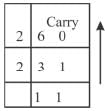
Hence, 6 =110
Now 0.25 x 2 = 0.50 → 0
0.50 x 2 = 1.00 → 1
0.00 x 2 = 0 → 0
Hence, 0.25 = 0.010 →1
Hence (6.25)2 = 110.010
The correct answer is: 110.01
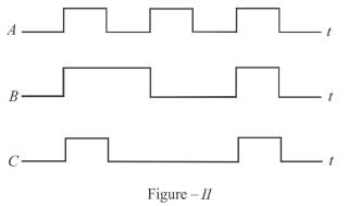
The given figure shows the wave forms for two inputs A and B and that for the output V of logic circuit. The logic circuit is :

- a)XOR gate
- b)NAND gate
- c)AND gate
- d)OR gate
Correct answer is option 'C'. Can you explain this answer?
The given figure shows the wave forms for two inputs A and B and that for the output V of logic circuit. The logic circuit is :
a)
XOR gate
b)
NAND gate
c)
AND gate
d)
OR gate

|
Pie Academy answered |
From the response of A, B and C, it is clear that C = A.B, hence, an AND gate.
The correct answer is: AND gate
The correct answer is: AND gate

The circuit shown in the figure below functions as
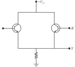
- a)AND gate
- b)NAND gate
- c)OR gate
- d)NOR gate
Correct answer is option 'C'. Can you explain this answer?
The circuit shown in the figure below functions as
a)
AND gate
b)
NAND gate
c)
OR gate
d)
NOR gate
|
|
Partho Gupta answered |
When A is high and B is low i.e. A = 1, B = 0 transistor A conducts and Y becomes high, i.e. Y = 1. If A = 0 and B = 1; transistor B conducts Y = 1, if A = 1 and B = 1; both transistors conduct. If A = B = 0. None of the transistors conducts hence Y= 0. The true table is shown below.
The correct answer is: OR gate
The correct answer is: OR gate

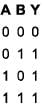
Which one of the following logic gate does the given truth table represent?
- a)NOT
- b)OR
- c)AND
- d)NOR
Correct answer is option 'C'. Can you explain this answer?
Which one of the following logic gate does the given truth table represent?
a)
NOT
b)
OR
c)
AND
d)
NOR
|
|
Priya Saha answered |
⇒ AND gate implies Y=A.B.
The correct answer is: AND
The correct answer is: AND
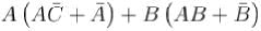
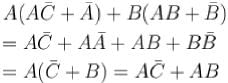
Which of the following sets of values given below satisfy the Boolean relation 
- a)P = 0, Q = 0, R = 0
- b)P = 1, Q = 0, R = 1
- c)P = 1, Q = 1, R = 0
- d)P = 1, Q = 1, R = 1
Correct answer is option 'A,B,C'. Can you explain this answer?
Which of the following sets of values given below satisfy the Boolean relation
a)
P = 0, Q = 0, R = 0
b)
P = 1, Q = 0, R = 1
c)
P = 1, Q = 1, R = 0
d)
P = 1, Q = 1, R = 1
|
|
Vandana Chopra answered |
The realization of the algebraic expression  in terms of logic gate is
Truth table.
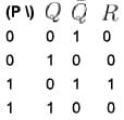
Hence, (a), (c), (d)
The correct answers are: P = 0, Q = 0, R = 0, P = 1, Q = 0, R = 1, P = 1, Q = 1, R = 0
in terms of logic gate isTruth table.
Hence, (a), (c), (d)
The correct answers are: P = 0, Q = 0, R = 0, P = 1, Q = 0, R = 1, P = 1, Q = 1, R = 0
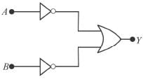


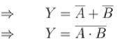

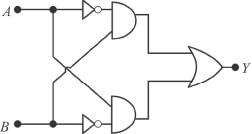
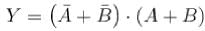
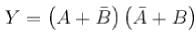
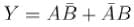
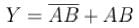
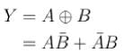
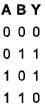
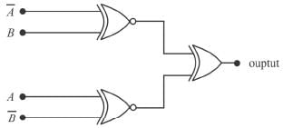
The Boolean expression of the output Y in terms of the inputs A and B for the circuit shown in the following figure is.
- a)
- b)
- c)
- d)
Correct answer is option 'C'. Can you explain this answer?
The Boolean expression of the output Y in terms of the inputs A and B for the circuit shown in the following figure is.
a)
b)
c)
d)
|
|
Srishti Khanna answered |
Equivalent circuit is
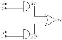
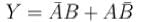
The correct answer is: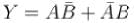
The correct answer is:
Which of the following options is false for a two input XOR gate?- a)
- b)
- c)
- d)
Correct answer is option 'B,C,D'. Can you explain this answer?
Which of the following options is false for a two input XOR gate?
a)
b)
c)
d)
|
|
Pie Academy answered |
The truth table for XOR gate is
The incorrect options are (b), (c), (d).
So answers are: (b), (c), (d).
The following circuit  does not performs the operation of.
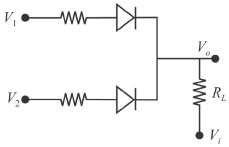
- a)NAND gate for a negative logic system
- b)AND gate for a positive logic system
- c)AND gate for a negative logic system
- d)OR gate for a negative logic system
Correct answer is option 'A,B,C'. Can you explain this answer?
The following circuit does not performs the operation of.
does not performs the operation of.a)
NAND gate for a negative logic system
b)
AND gate for a positive logic system
c)
AND gate for a negative logic system
d)
OR gate for a negative logic system
|
|
Pranavi Mishra answered |
If either V1 or V2 is high, we get a high in output, hence it each like an OR gate.
The correct answers are: NAND gate for a negative logic system, AND gate for a positive logic system, AND gate for a negative logic system
The correct answers are: NAND gate for a negative logic system, AND gate for a positive logic system, AND gate for a negative logic system
The number of bits that a digital computer can process in parallel at a time is called :- a)binary digit
- b)PACE
- c)word length
- d)byte
Correct answer is option 'C'. Can you explain this answer?
The number of bits that a digital computer can process in parallel at a time is called :
a)
binary digit
b)
PACE
c)
word length
d)
byte
|
|
Pie Academy answered |
The number of bits a digital computer can process in parallel at a time is referred to as the word length. This term defines the width of the data the computer can process in one cycle, often indicating the number of bits handled at once.
- Binary digit (Option A) refers to a single bit, either 0 or 1, which is too small a unit for this question.
- PACE (Option B) does not apply to the concept of processing bits in parallel.
- Byte (Option D) refers to a group of 8 bits, but it's not a term for processing multiple bits at once.
Thus, the best option is C: word length.
The output of the circuit in the figure is equal to.
Correct answer is '0'. Can you explain this answer?
The output of the circuit in the figure is equal to.
|
|
Abhijeet Majumdar answered |
The correct answer is: 0
The simplest logic gate circuit corresponding to Boolean expression
 is:
is:- a)
- b)
- c)
- d)
Correct answer is option 'D'. Can you explain this answer?
The simplest logic gate circuit corresponding to Boolean expression
is:
is:a)
b)
c)
d)
|
|
Bijoy Patel answered |

The output matches with

Hence, logic for
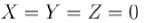
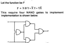
The function F generated by the logic network shown gives what output for
Correct answer is '0'. Can you explain this answer?
The function F generated by the logic network shown gives what output for
|
|
Stuti Patel answered |
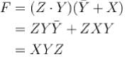
Hence
 gives
gives 
The correct answer is: 0
Find the output for A = 1, B = 0, C = 1.
Correct answer is '1'. Can you explain this answer?
Find the output for A = 1, B = 0, C = 1.
|
|
Sahil Kapoor answered |
The correct answer is: 1
The logic circuit shown in the following figure yields the given truth table.

The gate X in the diagram is. - a)NOR
- b)XOR
- c)NAND
- d)AND
Correct answer is option 'C'. Can you explain this answer?
The logic circuit shown in the following figure yields the given truth table.
The gate X in the diagram is.
The gate X in the diagram is.
a)
NOR
b)
XOR
c)
NAND
d)
AND
|
|
Sarthak Chavan answered |
The truth table of 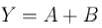
If X is NAND gate
Hence, Xis a NAND gate.
The correct answer is: NAND
If X is NAND gate
Hence, Xis a NAND gate.
The correct answer is: NAND
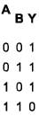
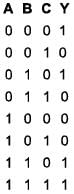
Which of the following gives the Boolean expression for Y of the 3-variable truth table Incorrect given below?
Truth table.
- a)
- b)
- c)

- d)

Correct answer is option 'A,D'. Can you explain this answer?
Which of the following gives the Boolean expression for Y of the 3-variable truth table Incorrect given below?
Truth table.
Truth table.
a)
b)
c)
d)
|
|
Vaibhav Ghosh answered |
The above truth table is satisfied by  further
The correct answers are:
furtherThe correct answers are:
The Boolean expression 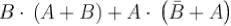 can be realized by how many minimum number of gates?
Correct answer is '1'. Can you explain this answer?
The Boolean expression can be realized by how many minimum number of gates?
can be realized by how many minimum number of gates?|
|
Sagarika Yadav answered |
Hence one two input AND gate is required.
∴ Minimum number of gate = 1.
The correct answer is: 1
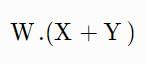
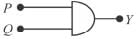
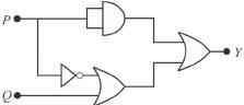
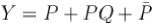
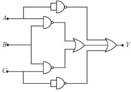
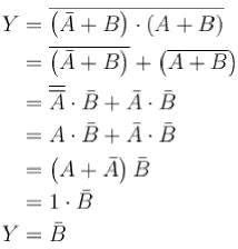
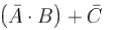
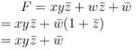
A logic circuit with an output 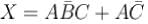 consists of :
- a)two AND gates and one OR gate
- b)two AND gates, one OR gate and one inverter
- c)two AND gates, one OR gate and two inverter
- d)two OR gates, one AND gate and two inverter
Correct answer is option 'C'. Can you explain this answer?
A logic circuit with an output consists of :
consists of :a)
two AND gates and one OR gate
b)
two AND gates, one OR gate and one inverter
c)
two AND gates, one OR gate and two inverter
d)
two OR gates, one AND gate and two inverter
|
|
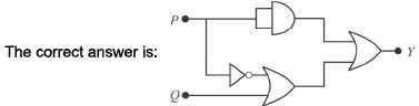
Sarthak Chavan answered |
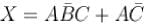 can be implemented through the following diagram,
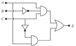
Which requires 2 AND gate, 1 OR gate and two inverters The correct answer is: two AND gates, one OR gate and two inverter


 and
and  are not available, what is the minimum number of two-input NAND gates require to implement
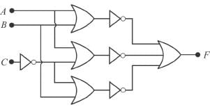
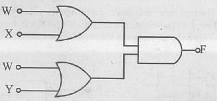
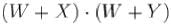
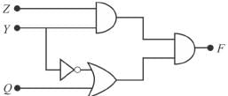
The diagram of a logic circuit is given below. The output F is best represented as.
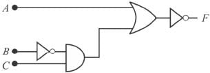
- a)

- b)

- c)

- d)

Correct answer is option 'C'. Can you explain this answer?
The diagram of a logic circuit is given below. The output F is best represented as.
a)
b)
c)
d)
|
|
Sarthak Chavan answered |
From the figure, 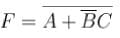
The correct answer is:
The correct answer is:
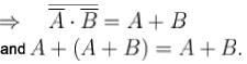
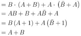
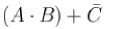
In Boolean Algebra, 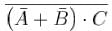 will be equal to.
- a)

- b)

- c)
- d)

Correct answer is option 'A'. Can you explain this answer?
In Boolean Algebra, will be equal to.
will be equal to.a)
b)
c)
d)
|
|
Anushka Basak answered |
The correct answer is:
In the given figure, circuit 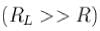 performs the operation of :
- a)AND gate for a positive logic system
- b)OR gate for a negative logic system
- c)NAND gate for a negative logic system
- d)AND gate for a negative logic system
Correct answer is option 'B'. Can you explain this answer?
In the given figure, circuit performs the operation of :
performs the operation of :a)
AND gate for a positive logic system
b)
OR gate for a negative logic system
c)
NAND gate for a negative logic system
d)
AND gate for a negative logic system
|
|
Sarthak Chavan answered |
If either V1 is positive or V2 is positive, V0 be positive, otherwise we get a low output for both V1 and V2 negative. Hence it acts as an OR gate.
The correct answer is: OR gate for a negative logic system
The correct answer is: OR gate for a negative logic system
The circuit shown in the figure can be used as :
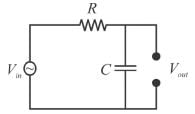
- a)Integrator
- b)Low-pass filter
- c)Differentiator
- d)High-pass filter
Correct answer is option 'A,B'. Can you explain this answer?
The circuit shown in the figure can be used as :
a)
Integrator
b)
Low-pass filter
c)
Differentiator
d)
High-pass filter
|
|
Pranavi Mishra answered |
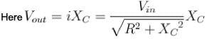
Hence, it is an integrator and a low-pass filter.
The correct answers are: Integrator, Low-pass filter
The logic function is defined as:f = [(x AND y) OR (z AND NOT x)] AND [NOT (x XOR z)]Evaluate the output of the function for: - x = 1
- y = 0
- z = 1
Correct answer is '0'. Can you explain this answer?
The logic function is defined as:
f = [(x AND y) OR (z AND NOT x)] AND [NOT (x XOR z)]
Evaluate the output of the function for:
- x = 1
- y = 0
- z = 1
|
|
Pie Academy answered |
Solution:
- Step 1: Simplify the first part:
- (x AND y):
- x = 1, y = 0 → (x AND y) = 1 AND 0 = 0.
- (z AND NOT x):
- z = 1, NOT x = 0 → (z AND NOT x) = 1 AND 0 = 0.
- (x AND y) OR (z AND NOT x):
- 0 OR 0 = 0.
- Step 2: Simplify the second part:
- (x XOR z):
- x = 1, z = 1 → (x XOR z) = 0 (since XOR is true only if inputs are different).
- NOT (x XOR z) = NOT 0 = 1.
- Step 3: Combine both parts:
- f = [(x AND y) OR (z AND NOT x)] AND [NOT (x XOR z)]
- f = 0 AND 1 = 0.
Final Answer:
The value of f is 0.
A half-adder is a digital circuit with :- a)two inputs and one outputs
- b)two inputs and two outputs
- c)three inputs and one outputs
- d)three inputs and two outputs
Correct answer is option 'B'. Can you explain this answer?
A half-adder is a digital circuit with :
a)
two inputs and one outputs
b)
two inputs and two outputs
c)
three inputs and one outputs
d)
three inputs and two outputs
|
|
Sarthak Chavan answered |
The algebraic expression of half-adder are

The correct answer is: two inputs and two outputs
What is the output for X = 1, Y = 0 for the logic circuit drawn below :
Correct answer is '1'. Can you explain this answer?
What is the output for X = 1, Y = 0 for the logic circuit drawn below :
|
|
Preethi Joshi answered |
The truth table for the above circuit is.
Hence, for X = 1, Y = 0, output = 1
The correct answer is: 1
Hence, for X = 1, Y = 0, output = 1
The correct answer is: 1
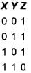
Consider following gate network which of the following gate is redundant write the gate number____ ?
Correct answer is '2'. Can you explain this answer?
Consider following gate network which of the following gate is redundant write the gate number____ ?
|
|
Abhijeet Majumdar answered |
Before gate Number 2 being remove, output
⇒ gate number 2 is redundant.
The correct answer is: 2
⇒ gate number 2 is redundant.
The correct answer is: 2
Chapter doubts & questions for Digital Electronics - Electronics for GATE 2025 is part of GATE Physics exam preparation. The chapters have been prepared according to the GATE Physics exam syllabus. The Chapter doubts & questions, notes, tests & MCQs are made for GATE Physics 2025 Exam. Find important definitions, questions, notes, meanings, examples, exercises, MCQs and online tests here.
Chapter doubts & questions of Digital Electronics - Electronics for GATE in English & Hindi are available as part of GATE Physics exam.
Download more important topics, notes, lectures and mock test series for GATE Physics Exam by signing up for free.
Electronics for GATE
55 videos|28 docs|20 tests
|
|
© EduRev
|
Education Revolution
|


|


Signup on EduRev and stay on top of your study goals
10M+ students crushing their study goals daily