


All Exams >
Mechanical Engineering >
GATE Mechanical (ME) Mock Test Series 2026 >
All Questions
All questions of Practice Test: Full Length for Mechanical Engineering Exam
Statements:
All pillows are beds.
No fruit is pillow.
Some foods are fruits.
Conclusions:
I. At least some foods are pillows.
II. Some beds are definitely fruits.- a)Only Conclusions I follows
- b)Only Conclusions II follows
- c)Either Conclusion I or Conclusions II follows
- d)Neither Conclusions I nor Conclusion II follows
Correct answer is option 'D'. Can you explain this answer?
Statements:
All pillows are beds.
No fruit is pillow.
Some foods are fruits.
Conclusions:
I. At least some foods are pillows.
II. Some beds are definitely fruits.
All pillows are beds.
No fruit is pillow.
Some foods are fruits.
Conclusions:
I. At least some foods are pillows.
II. Some beds are definitely fruits.
a)
Only Conclusions I follows
b)
Only Conclusions II follows
c)
Either Conclusion I or Conclusions II follows
d)
Neither Conclusions I nor Conclusion II follows
|
|
Ravi Singh answered |
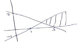
Consider the following least possible Venn diagram,

Conclusions:
I. At least some foods are pillows → it’s possible but not definite, hence false.
II. Some beds are definitely fruits → it’s possible but not definite, hence false.
Conclusions:
I. At least some foods are pillows → it’s possible but not definite, hence false.
II. Some beds are definitely fruits → it’s possible but not definite, hence false.

A block is displaced by 3 m when a force of 200 N is applied on it on an inclined surface which is at an angle of 50o with the horizontal. What is the work done?- a)459.62 Nm
- b)385.67 Nm
- c)933.00 Nm
- d)Insufficient data
Correct answer is option 'B'. Can you explain this answer?
A block is displaced by 3 m when a force of 200 N is applied on it on an inclined surface which is at an angle of 50o with the horizontal. What is the work done?
a)
459.62 Nm
b)
385.67 Nm
c)
933.00 Nm
d)
Insufficient data

|
EduRev GATE answered |
Given: Force = 200 N, θ = 50°, block displacement (D) = 3m
Formula: Work done = Force x cos θ x D
Work done = Force x cos θ x D
= 200 x cos 50 x 3 = 385.67 Nm
Work done = 385.67 Nm
Formula: Work done = Force x cos θ x D
Work done = Force x cos θ x D
= 200 x cos 50 x 3 = 385.67 Nm
Work done = 385.67 Nm
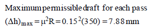
T he thickness of a plate is to be reduced from 50 mm to 25 mm in a number of cold rolling passes. T he roll
radius is 350 mm and the coefficient of friction is estimated to be 0.15. T he maximum promissible draft for
each pass ______________
Correct answer is between '7.5,8.5'. Can you explain this answer?
T he thickness of a plate is to be reduced from 50 mm to 25 mm in a number of cold rolling passes. T he roll
radius is 350 mm and the coefficient of friction is estimated to be 0.15. T he maximum promissible draft for
each pass ______________
radius is 350 mm and the coefficient of friction is estimated to be 0.15. T he maximum promissible draft for
each pass ______________

|
Cstoppers Instructors answered |
The ratio between the speed of a bus and train is 15 : 27, respectively. Also, a car covered a distance of 720 km in 9 h. the speed of the bus is three- fourth of the speed of the car. How much distance will the train cover on 7 h?- a)860 km
- b)756 km
- c)940 km
- d)Cannot be determined
Correct answer is option 'B'. Can you explain this answer?
The ratio between the speed of a bus and train is 15 : 27, respectively. Also, a car covered a distance of 720 km in 9 h. the speed of the bus is three- fourth of the speed of the car. How much distance will the train cover on 7 h?
a)
860 km
b)
756 km
c)
940 km
d)
Cannot be determined
|
|
Sanvi Kapoor answered |
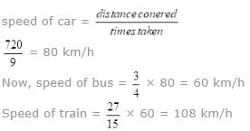
Distance covered by train in 7 h = 108 × 7 = 756 km
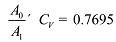
A fluid jet is discharging from a 100 mm nozzle and the vena contracta formed has a diameter of 90 mm. If the coefficient of velocity is 0.95, then the coefficient of discharge for the nozzle is.- a)0.855
- b)0.81
- c) 0.9025
- d) 0.7695
Correct answer is option 'D'. Can you explain this answer?
A fluid jet is discharging from a 100 mm nozzle and the vena contracta formed has a diameter of 90 mm. If the coefficient of velocity is 0.95, then the coefficient of discharge for the nozzle is.
a)
0.855
b)
0.81
c)
0.9025
d)
0.7695
|
|
Rhea Reddy answered |


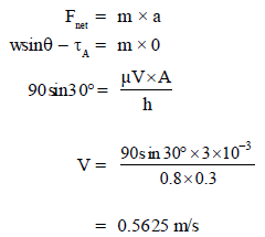
A 90 N rectangular solid block slides down a 30° inclined plane. The plane is lubrt icated by 3mm thick film
oil of specific gravit y 0.9 & viscosity 8 poise. If the contact area is 0.3m2, find the terminal velocity of the
block
Correct answer is between '0.50,0.60'. Can you explain this answer?
A 90 N rectangular solid block slides down a 30° inclined plane. The plane is lubrt icated by 3mm thick film
oil of specific gravit y 0.9 & viscosity 8 poise. If the contact area is 0.3m2, find the terminal velocity of the
block
oil of specific gravit y 0.9 & viscosity 8 poise. If the contact area is 0.3m2, find the terminal velocity of the
block
|
|
Neha Joshi answered |
Applying Ne wton’s IInd law along t he inclined plane
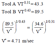
A mild steel workpiece is being machined by two different tools 'A' and 'B' under identical machining conditions. The tool life equation for these tools are
Tool A VT0.31 = 43.3
Tool B VT0.43 = 89.5
Where V and T are in m/s, respectively. Determine the cutting speed above which tool B will give better tool
life__________________ m/s
Correct answer is between '4.6,4.8'. Can you explain this answer?
A mild steel workpiece is being machined by two different tools 'A' and 'B' under identical machining conditions. The tool life equation for these tools are
Tool A VT0.31 = 43.3
Tool B VT0.43 = 89.5
Where V and T are in m/s, respectively. Determine the cutting speed above which tool B will give better tool
life
Tool A VT0.31 = 43.3
Tool B VT0.43 = 89.5
Where V and T are in m/s, respectively. Determine the cutting speed above which tool B will give better tool
life
__________________ m/s
|
|
Debolina Menon answered |
At break-even speed V* both tool gives the same tool life
In a reverted gear train the pinion (20 teeth) drives a gear B (60 teeth). The gear B and pinion C (15 teeth) are compounded. The pinion C drives the output gear D (45 teeth). The module for the first stage is 3. The module for the second stage and the velocity ratio are respectively:- a)3 and 9
- b)4 and 3
- c)3 and 1
- d)4 and 9
Correct answer is option 'D'. Can you explain this answer?
In a reverted gear train the pinion (20 teeth) drives a gear B (60 teeth). The gear B and pinion C (15 teeth) are compounded. The pinion C drives the output gear D (45 teeth). The module for the first stage is 3. The module for the second stage and the velocity ratio are respectively:
a)
3 and 9
b)
4 and 3
c)
3 and 1
d)
4 and 9

|
Srestha Datta answered |
Reverted Gear Train Calculation
First Stage: Pinion A (20 teeth) drives Gear B (60 teeth)
- Module: 3
- Velocity Ratio: 60/20 = 3
Second Stage: Gear B and Pinion C (15 teeth) are compounded and drives Output Gear D (45 teeth)
- Module: ?
- Velocity Ratio: 45/15 = 3
To find the module for the second stage, we can use the formula:
Module = (Pitch Diameter of Driven Gear - Pitch Diameter of Driving Gear) / Number of Teeth on the Driving Gear
Pitch Diameter of Gear B = Module x Number of Teeth on Gear B
= 3 x 60
= 180 mm
Pitch Diameter of Pinion C = Module x Number of Teeth on Pinion C
= M x 15
Since Gear B and Pinion C are compounded, their pitch circles are the same size. Therefore, we can set their pitch diameters equal to each other:
180 = M x 60/15
M = 4 mm
Therefore, the module for the second stage is 4 mm and the velocity ratio is 3. Multiplying the velocity ratios of both stages, we get a total velocity ratio of 3 x 3 = 9.
Hence, the correct answer is option D (4 and 9).
A metallic ball in shape of sphere is made up of steel (thermal conductivity of 35W/m-K) of diameter 0.38 m . The outside heat transfer coefficient is 15W/m2. It is to be insulated with film of thermal conductivity 3W/m-K. The thickness of insulation should be- a)0.21m
- b)0.02m
- c)0.38m
- d)0.19m
Correct answer is option 'A'. Can you explain this answer?
A metallic ball in shape of sphere is made up of steel (thermal conductivity of 35W/m-K) of diameter 0.38 m . The outside heat transfer coefficient is 15W/m2. It is to be insulated with film of thermal conductivity 3W/m-K. The thickness of insulation should be
a)
0.21m
b)
0.02m
c)
0.38m
d)
0.19m
|
|
Sonal Deshpande answered |
Thickness=0.4-0.19=0.21m
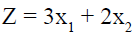
Consider the following linear programming problem:Maximize Z =2A+3B, Subject to A+B ≤10, 4A+6B≤30, 2A+B≤17, A,B≥0What can one say about the solution?- a)It may contain alternative optimal solution.
- b)The solution will be unbounded
- c)The solution will be degenerate.
- d)It cannot be solved by simplex method.
Correct answer is option 'A'. Can you explain this answer?
Consider the following linear programming problem:
Maximize Z =2A+3B, Subject to A+B ≤10, 4A+6B≤30, 2A+B≤17, A,B≥0
What can one say about the solution?
a)
It may contain alternative optimal solution.
b)
The solution will be unbounded
c)
The solution will be degenerate.
d)
It cannot be solved by simplex method.
|
|
Ravi Singh answered |
Z = 2A + 3B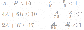
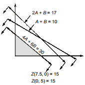
Maximum value of objective functions = 15 and it has alternative optimal solutions because of same constraint as objective function.
In a engine working on otto cycle the temp. at the beginning and end of the compression are 500C and 3730C . The compression ratio and air standard efficiency of the engine is.- a)1.219 and 40%
- b)5.66 and 50 %
- c)1.219 and 50%
- d)5.66 and 40%
Correct answer is option 'B'. Can you explain this answer?
In a engine working on otto cycle the temp. at the beginning and end of the compression are 500C and 3730C . The compression ratio and air standard efficiency of the engine is.
a)
1.219 and 40%
b)
5.66 and 50 %
c)
1.219 and 50%
d)
5.66 and 40%
|
|
Arnav Menon answered |
Compression ratio,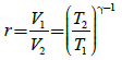
= 0.5 = 50 %
In a certain double pipe heat exchanger hot water flow at a rate of 5000 kg/h. and gets cooled from 950C to 650C . At the same time,50000 kg/h of cooling water at 300C enters the heat exchanger. The flow conditions, are such that overall heat transfer coefficient remains constant at 2270 W/m2K. Assume two streams are in parallel flow and for both the streams Cp = 4.2 kJ/kg K. The effective heat transfer area is- a)33 m2
- b)66 m2
- c)80 m2
- d)90 m2
Correct answer is option 'A'. Can you explain this answer?
In a certain double pipe heat exchanger hot water flow at a rate of 5000 kg/h. and gets cooled from 950C to 650C . At the same time,50000 kg/h of cooling water at 300C enters the heat exchanger. The flow conditions, are such that overall heat transfer coefficient remains constant at 2270 W/m2K. Assume two streams are in parallel flow and for both the streams Cp = 4.2 kJ/kg K. The effective heat transfer area is
a)
33 m2
b)
66 m2
c)
80 m2
d)
90 m2
|
|
Sagnik Choudhary answered |
Given data:
Hot water flow rate = 5000 kg/h
Inlet temperature of hot water = 95°C
Outlet temperature of hot water = 65°C
Cooling water flow rate = 50000 kg/h
Inlet temperature of cooling water = 30°C
Overall heat transfer coefficient = 2270 W/m2K
Specific heat of both the streams = 4.2 kJ/kgK
To determine: Effective heat transfer area of the heat exchanger
Calculation:
Heat transfer rate = m1*Cp1*(T1-T2)
where,
m1 = Hot water flow rate = 5000 kg/h = 1.39 kg/s
Cp1 = Specific heat of hot water = 4.2 kJ/kgK
T1 = Inlet temperature of hot water = 95°C = 368 K
T2 = Outlet temperature of hot water = 65°C = 338 K
Heat transfer rate = 1.39*4.2*(368-338) = 179.892 kW
Heat transfer rate = m2*Cp2*(T2-T1)
where,
m2 = Cooling water flow rate = 50000 kg/h = 13.89 kg/s
Cp2 = Specific heat of cooling water = 4.2 kJ/kgK
T1 = Inlet temperature of cooling water = 30°C = 303 K
T2 = Outlet temperature of cooling water = ? (to be determined)
Heat transfer rate = 13.89*4.2*(T2-303)
Overall heat transfer coefficient, U = 2270 W/m2K
Area of heat transfer, A = Q/(U*(ΔTm))
where,
Q = Heat transfer rate = 179.892 kW
ΔTm = Logarithmic mean temperature difference
ΔT1 = T1 - T2 = 368 - 338 = 30 K
ΔT2 = T2 - T1 = T2 - 368
ΔTm = (ΔT1 - ΔT2)/ln(ΔT1/ΔT2)
ΔTm = (30 - (T2-368))/ln(30/(T2-368))
Substituting the values in the above equation, we get:
ΔTm = (30 - T2 + 368)/ln(30/(T2-368))
Substituting ΔTm in the area equation, we get:
A = 179.892/(2270*((30-T2+368)/ln(30/(T2-368))))
Solving for A, we get:
A = 33 m2 (approx)
Therefore, the effective heat transfer area of the heat exchanger is 33 m2.
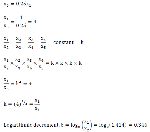
In the production shop of a company the breakdown of the machine is found to follow poisson distribution with an average rate of 3 machines per hour. Break down time at one machine
costs 40 rupees per hour to the company. The company hires a repairman who demands rupees 20 per hour and will repair the broken down machines following the exponential distribution at the rate of 4 per hour. The total cost involved in hiring the repairman is- a)250
- b)180
- c)130
- d)210
Correct answer is option 'B'. Can you explain this answer?
In the production shop of a company the breakdown of the machine is found to follow poisson distribution with an average rate of 3 machines per hour. Break down time at one machine
costs 40 rupees per hour to the company. The company hires a repairman who demands rupees 20 per hour and will repair the broken down machines following the exponential distribution at the rate of 4 per hour. The total cost involved in hiring the repairman is
costs 40 rupees per hour to the company. The company hires a repairman who demands rupees 20 per hour and will repair the broken down machines following the exponential distribution at the rate of 4 per hour. The total cost involved in hiring the repairman is
a)
250
b)
180
c)
130
d)
210
|
|
Bibek Das answered |
λ = 3/hr
μ = 4/hr
Total waiting time in system for one machine is
=  = 1 hour
= 1 hourThe down time of 3 machines is
= 3 × 1 = 3 hour
Down time cost = 40 × 3 = Rs 120
Repairman cost = 3 × 20 = Rs 60
Total cost = 120 60 = Rs 180
= 3 × 1 = 3 hour
Down time cost = 40 × 3 = Rs 120
Repairman cost = 3 × 20 = Rs 60
Total cost = 120 60 = Rs 180
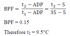
In a certain cooling dehumidification operation, 360 kg/h of air (DBT 35°C & RH 50%) is blown over a cooling coil having apparatus dew point of 5°C, assuming a bypass factor 15% determine outlet conditions of air- a)7°C
- b)12°C
- c) 9.5°C
- d)14°C
Correct answer is option 'C'. Can you explain this answer?
a)
7°C
b)
12°C
c)
9.5°C
d)
14°C
|
|
Cstoppers Instructors answered |
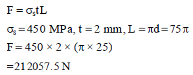
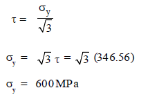
According to Von–Mises criterion, the shear yield stress of the material is 346.56 MPa t hen what will
be t he yield strength of this material in tension assume unidirectional loading _____________MPa
Correct answer is between '590,610'. Can you explain this answer?
According to Von–Mises criterion, the shear yield stress of the material is 346.56 MPa t hen what will
be t he yield strength of this material in tension assume unidirectional loading _____________MPa
be t he yield strength of this material in tension assume unidirectional loading _____________MPa
|
|
Sanvi Kapoor answered |
Von – Mises criterion gives
What is the deformation or dynamic factor if sum of errors on meshing teeth of steel pinion and gear is 32 x 10-3 mm?- a) 284.8 N/mm
- b) 300.23 N/mm
- c) 320.5 N/mm
- d) 368 N/mm
Correct answer is option 'D'. Can you explain this answer?
What is the deformation or dynamic factor if sum of errors on meshing teeth of steel pinion and gear is 32 x 10-3 mm?
a)
284.8 N/mm
b)
300.23 N/mm
c)
320.5 N/mm
d)
368 N/mm

|
Anirban Khanna answered |
For steel and pinion gears tooth form factor (K) is 0.111 and modulus of elasticity for pinion and gear is 207 x 103 N/mm2.
Substituting these values in formula for deformation factor
C = K.e [(Ep x Eg ) / (Ep + Eg )]
C = 11500e
Therefore substituting value of e = 32 x 10-3, we get
C = 368 N/mm
A plastic pipe (K = 0.5 W/mK) carries a fluid such that the convective heat transfer coefficient is 200 W/
m2K. The average fluid temperat ure is 100°C. T he pipe has an inner diameter of 3 cm and outer diameter
4 cm. If the heat transfer rat e t hrough the pipe per unit length is 450 W/m, calculate the external pipe
temperat ure- a)41.23°C
- b)82.46°C
- c)48.27°C
- d)58.77°C
Correct answer is option 'D'. Can you explain this answer?
A plastic pipe (K = 0.5 W/mK) carries a fluid such that the convective heat transfer coefficient is 200 W/
m2K. The average fluid temperat ure is 100°C. T he pipe has an inner diameter of 3 cm and outer diameter
4 cm. If the heat transfer rat e t hrough the pipe per unit length is 450 W/m, calculate the external pipe
temperat ure
m2K. The average fluid temperat ure is 100°C. T he pipe has an inner diameter of 3 cm and outer diameter
4 cm. If the heat transfer rat e t hrough the pipe per unit length is 450 W/m, calculate the external pipe
temperat ure
a)
41.23°C
b)
82.46°C
c)
48.27°C
d)
58.77°C
|
|
Yash Patel answered |
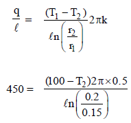
41.23 = 100 – T2
T2 = 58.77 °C
T2 = 58.77 °C
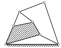
Figure shows the cross-section of a cast iron beam. Determine the moments of inertia of the section about horizontal axis passing through the centroid of the section.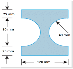
- a)IXX= 19.97× 106 mm4
- b)IXX = 22.97 × 106 mm4
- c)IXX = 15.21× 106 mm4
- d)IXX = 17.11× 106 mm4
Correct answer is option 'A'. Can you explain this answer?
Figure shows the cross-section of a cast iron beam. Determine the moments of inertia of the section about horizontal axis passing through the centroid of the section.
a)
IXX= 19.97× 106 mm4
b)
IXX = 22.97 × 106 mm4
c)
IXX = 15.21× 106 mm4
d)
IXX = 17.11× 106 mm4

|
Sirisha Avala answered |
Determine the moments of inertia of the section shown in figure 3 about horizontal
and vertical axes passing through the centroid of the section.
and vertical axes passing through the centroid of the section.
There are 200 individuals with a skin disorder, 120 had been exposed to the chemical c1, 50 to chemical c2, and 30 to both chemicals c1 and c2. find the number of individuals exposed to chemical c2 but not chemical c1
- a)90
- b)20
- c)140
- d)50
Correct answer is option 'B'. Can you explain this answer?
There are 200 individuals with a skin disorder, 120 had been exposed to the chemical c1, 50 to chemical c2, and 30 to both chemicals c1 and c2. find the number of individuals exposed to chemical c2 but not chemical c1
a)
90
b)
20
c)
140
d)
50
|
|
Yash Patel answered |
Let U= set of individuals suffering from the skin disorder
A= set of individuals exposed to the chemical c1
B= set of individual exposed to the chemical c2
Then n(u)=200, n(A)=120, n(B)=50 and n(A∩B)=30
Similarly, B=(B−A)∪(A∩B)
∴n(B)=n(B−A)+n(A∩B)
∵n(B−A)∩(A∩B)=φ
∴n(B−A)=n(B)−n(A∩B)
=50−30=20
Hence, 20 individuals exposed to chemical c2 but not to chemical c1
A cold rolled steel shaft is designed on the basis of maximum shear stress theory. The principal stresses induced at its critical section are 60 MPa and -60 MPa respectively. If the yield stress for the shaft material is 360 MPa, the factor of safety of the design is:- a)2
- b)3
- c)4
- d)6
Correct answer is option 'B'. Can you explain this answer?
A cold rolled steel shaft is designed on the basis of maximum shear stress theory. The principal stresses induced at its critical section are 60 MPa and -60 MPa respectively. If the yield stress for the shaft material is 360 MPa, the factor of safety of the design is:
a)
2
b)
3
c)
4
d)
6
|
|
Nitin Joshi answered |
Calculation of Maximum Shear Stress
The maximum shear stress theory states that failure occurs in a material when the maximum shear stress at a point exceeds the shear stress at yield point of a material.
τmax = (σ1 - σ2) / 2
where,
τmax = maximum shear stress
σ1 = maximum principal stress
σ2 = minimum principal stress
Given, σ1 = 60 MPa and σ2 = -60 MPa
τmax = (60 - (-60)) / 2 = 60 MPa
Calculation of Factor of Safety
The factor of safety is the ratio of the yield stress of the material to the maximum shear stress induced in the material.
Factor of safety = Yield stress / Maximum shear stress
Given, yield stress = 360 MPa and maximum shear stress = 60 MPa
Factor of safety = 360 / 60 = 6
Therefore, the factor of safety of the design is 6, which means that the design is safe as it can withstand six times the maximum shear stress induced in the material. The correct option is (B).
A Flat smooth rectangular plate is placed edgewise in a stream of fluid. At what fraction of the length from the leading edge would the drag force on the front portion be equal to the half of the total drag force? Assume the boundary layer to be laminar.- a)1/4
- b)1/2
- c)3/4
- d)1
Correct answer is option 'A'. Can you explain this answer?
a)
1/4
b)
1/2
c)
3/4
d)
1

|
Subhankar Malik answered |


A turbine develops 900 kW when running at 200 r.p.m. The head on the turbine is 30 m. If the head on the turbine is reduced to 18 m, determine the speed of the turbine (in rpm).
Correct answer is between '154,155'. Can you explain this answer?
A turbine develops 900 kW when running at 200 r.p.m. The head on the turbine is 30 m. If the head on the turbine is reduced to 18 m, determine the speed of the turbine (in rpm).

|
Rutuja Pillai answered |
Solution:
Given:
Power developed by the turbine, P1 = 900 kW
Speed of the turbine, N1 = 200 rpm
Head on the turbine, H1 = 30 m
New head on the turbine, H2 = 18 m
To find: Speed of the turbine, N2
Assumptions:
The turbine is operating under Francis Turbine conditions.
The change in head does not affect the efficiency of the turbine.
Formulae:
The formula to find the power developed by the turbine is given by:
P = γQH
Where,
P is the power developed by the turbine
γ is the specific weight of the fluid (taken as 9810 N/m3 for water)
Q is the discharge through the turbine
H is the head on the turbine
The specific speed of the turbine is given by:
N_s = N√Q/H^(3/4)
Where,
N is the speed of the turbine
Q is the discharge through the turbine
H is the head on the turbine
Calculation:
From the given data, we can find the discharge through the turbine for the given power and head as follows:
P1 = γQ1H1
900 × 10^3 = 9810 × Q1 × 30
Q1 = 3.06 m3/s
Using the specific speed formula, we get:
N_s1 = N1√(Q1/H1^(3/4))
200 = N1 √(3.06/30^(3/4))
N1 = 168.67 rpm
Now, using the discharge formula, we can find the discharge through the turbine for the new head as follows:
Q2 = Q1(H2/H1)
Q2 = 3.06(18/30)
Q2 = 1.84 m3/s
Using the specific speed formula, we get:
N_s2 = N2√(Q2/H2^(3/4))
N_s2 = N1√(Q2/H2^(3/4))
N2 = (N_s2/N_s1)² × N1
N2 = (18/30)^(3/4) × 200
N2 = 154.3 rpm
Therefore, the speed of the turbine is 154.3 rpm (rounded to the nearest integer).
Conclusion:
The speed of the turbine when the head is reduced from 30 m to 18 m is 154.3 rpm (rounded to the nearest integer).
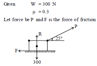
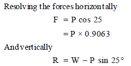
A body of weight 300 N is lying on a rough horizontal plane having a coefficient of frict ion as 0.3. What
would be the magnitude of the force, which can move the body, while acting at an angle of 25° with the
horizontal?- a)67 N
- b)77 N
- c)87 N
- d)97 N
Correct answer is option 'C'. Can you explain this answer?
A body of weight 300 N is lying on a rough horizontal plane having a coefficient of frict ion as 0.3. What
would be the magnitude of the force, which can move the body, while acting at an angle of 25° with the
horizontal?
would be the magnitude of the force, which can move the body, while acting at an angle of 25° with the
horizontal?
a)
67 N
b)
77 N
c)
87 N
d)
97 N
|
|
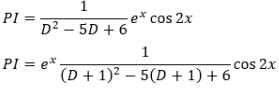
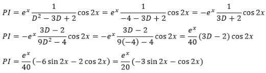
Gowri Sharma answered |
 is a Partial differential equation whose solution is given by

The value of K is- a)20
- b)1/20
- c)40
- d)1/40
Correct answer is option 'B'. Can you explain this answer?
is a Partial differential equation whose solution is given byThe value of K is
a)
20
b)
1/20
c)
40
d)
1/40
|
|
Rhea Reddy answered |
The objective here is to find the Particular integral as Complementary function is already given in the solution.
In spot pulsed laser welding of aluminum plates (density = 2700  specific heat =896J/kg, melting temperature = 933K, latent heat of melting is 380 kJ/kg) at a temperature of
  Pulse with energy of 0.5 J is focused on to area of 0.05 mm2. If the entire energy is coupled into the material. What will be depth of weld assuming crosssection area of weld as circular and uniform throughout depth and only heat conduction in direction of penetration?
 - a)5.34 mm
- b) 2.15 mm
- c) 4.23 mm
- d)3.85 mm
Correct answer is option 'D'. Can you explain this answer?
specific heat =896J/kg, melting temperature = 933K, latent heat of melting is 380 kJ/kg) at a temperature of Pulse with energy of 0.5 J is focused on to area of 0.05 mm2. If the entire energy is coupled into the material. What will be depth of weld assuming crosssection area of weld as circular and uniform throughout depth and only heat conduction in direction of penetration? a)
5.34 mm
b)
2.15 mm
c)
4.23 mm
d)
3.85 mm

|
Gate Funda answered |
Let depth = d
Volume of weld = Ad
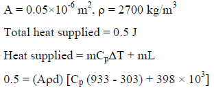
d = 3.84 mm
Volume of weld = Ad
d = 3.84 mm
A hole with 40 mm diameter and 50 mm depth is to be drilled in mild steel component. The cutting speed can be taken as 65 m/min and feed rate is 0.25 mm/rev. The time required to drill
the hole in minutes is [Take drill point angle1180 and over travel 3mm]- a)0.5
- b)0.6
- c)0.4
- d)0.7
Correct answer is option 'A'. Can you explain this answer?
A hole with 40 mm diameter and 50 mm depth is to be drilled in mild steel component. The cutting speed can be taken as 65 m/min and feed rate is 0.25 mm/rev. The time required to drill
the hole in minutes is [Take drill point angle1180 and over travel 3mm]
the hole in minutes is [Take drill point angle1180 and over travel 3mm]
a)
0.5
b)
0.6
c)
0.4
d)
0.7
|
|
Avik Ghosh answered |
Given data:
Diameter of hole = 40 mm
Depth of hole = 50 mm
Cutting speed = 65 m/min
Feed rate = 0.25 mm/rev
Drill point angle = 1180
Over travel = 3 mm
We need to calculate the time required to drill the hole.
Formula used:
Cutting speed = (π × D × N) / 1000
Where,
D = Diameter of the drill
N = Rotational speed of the drill
Feed per revolution = feed rate × no. of flutes
Time taken = Length of hole / feed rate
Calculation:
Given, drill diameter = 40 mm
∴ Rotational speed of the drill N = (Cutting speed × 1000) / (π × D)
= (65 × 1000) / (π × 40)
= 517.4 rpm
Feed per revolution = feed rate × no. of flutes
= 0.25 × 2
= 0.5 mm
Effective diameter of the drill = 40 - (0.5 × tan(1180/2))
= 39.05 mm
Total length of the hole = 50 + 3
= 53 mm
Time taken = Length of hole / feed rate
= 53 / 0.5
= 106 minutes
Therefore, the time required to drill the hole is 0.5 minutes (option A).
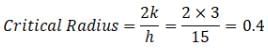
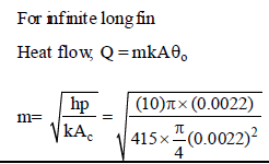
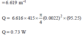
A infinit e length copper fin of k = 415 W/mK and 0.22 cm in diameter produces from a wall at 95°C int o
ambient air at 25°C. Heat transfer coefficient for free convection is e qual t o 10 W/m2K, find the heat
trasnfer from the fin- a)0.626 W
- b)0.109 W
- c)0.73 W
- d)0.83 W
Correct answer is option 'C'. Can you explain this answer?
A infinit e length copper fin of k = 415 W/mK and 0.22 cm in diameter produces from a wall at 95°C int o
ambient air at 25°C. Heat transfer coefficient for free convection is e qual t o 10 W/m2K, find the heat
trasnfer from the fin
ambient air at 25°C. Heat transfer coefficient for free convection is e qual t o 10 W/m2K, find the heat
trasnfer from the fin
a)
0.626 W
b)
0.109 W
c)
0.73 W
d)
0.83 W
|
|
Neha Joshi answered |
 Subject to
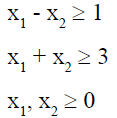
Amit rows a boat 9 kilometres in 2 hours down-stream and returns upstream in 6 hours. The speed of the boat (in kmph) is:- a)1.5
- b)3
- c)2
- d)1.75
Correct answer is option 'B'. Can you explain this answer?
Amit rows a boat 9 kilometres in 2 hours down-stream and returns upstream in 6 hours. The speed of the boat (in kmph) is:
a)
1.5
b)
3
c)
2
d)
1.75
|
|
Tanishq Chakraborty answered |
Down-stream rate = 9/2 = 4.5 kmph
Upstream rate = 9/6 = 1.5 kmph
The speed of the boat = (4.5 – 1.5) kmph = 3 kmph
Upstream rate = 9/6 = 1.5 kmph
The speed of the boat = (4.5 – 1.5) kmph = 3 kmph
Flow separation is caused by- a)Reduction of pressure to local vapour pressure
- b)A negative pressure gradient
- c)A positive pressure gradient
- d)Thinning of boundary layer thickness to zero
Correct answer is option 'C'. Can you explain this answer?
a)
Reduction of pressure to local vapour pressure
b)
A negative pressure gradient
c)
A positive pressure gradient
d)
Thinning of boundary layer thickness to zero

|
Nikhil Majumdar answered |
Positive pressure gradient is adverse pressure gradient which causes flow separation
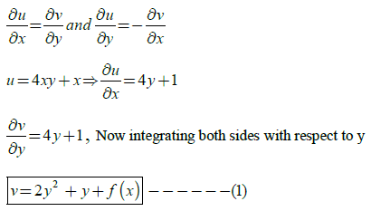
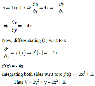
For an analytic function f (x iy) = u (x, y) iv (x, y), u is given by u = 4xy+ x. The expression for V considering K to be a constant
- a)y2 – 2y – 4x+ K
- b) x2+ y+ 4x
- c) 2y2 + y – 2x2 + K
- d) - 4xy+ K
Correct answer is option 'C'. Can you explain this answer?
For an analytic function f (x iy) = u (x, y) iv (x, y), u is given by u = 4xy+ x. The expression for V considering K to be a constant
a)
y2 – 2y – 4x+ K
b)
x2+ y+ 4x
c)
2y2 + y – 2x2 + K
d)
- 4xy+ K
|
|
Nidhi Patel answered |
Since f is analytic, it will satisfy Cauchy. Riemann equations
During orthogonal cutting with a 0° rack angle tool, the cutting and thrust forces were measured as 968 N
and 455 N respectively. Determine the coefficient of friction _____________
Correct answer is between '0.45,0.50'. Can you explain this answer?
During orthogonal cutting with a 0° rack angle tool, the cutting and thrust forces were measured as 968 N
and 455 N respectively. Determine the coefficient of friction _____________
and 455 N respectively. Determine the coefficient of friction _____________
|
|
Soumya Basak answered |
Understanding Cutting Forces
In orthogonal cutting, the cutting force (\(F_c\)) and thrust force (\(F_t\)) are critical for determining the coefficient of friction (\(\mu\)) between the cutting tool and the workpiece.
Given Values
- Cutting Force, \(F_c = 968 \, N\)
- Thrust Force, \(F_t = 455 \, N\)
Coefficient of Friction Formula
The coefficient of friction can be calculated using the following formula:
\[
\mu = \frac{F_t}{F_c}
\]
Calculation Steps
1. **Insert Values into the Formula**:
\[
\mu = \frac{455 \, N}{968 \, N}
\]
2. **Perform the Calculation**:
\[
\mu = 0.470
\]
Interpretation of Results
- The calculated coefficient of friction \(\mu \approx 0.47\) falls within the specified range of 0.45 to 0.50.
- This value indicates moderate frictional resistance between the cutting tool and the workpiece material during the cutting process.
Factors Influencing Friction
- **Tool Material**: Harder materials generally exhibit lower friction.
- **Cutting Speed**: Higher speeds can reduce friction due to thermal effects.
- **Lubrication**: The presence of cutting fluids can significantly alter the friction coefficient.
Understanding these factors helps in optimizing cutting processes and improving tool life and surface finish.
A shaft of 300 mm diameter is carrying a load of 20 kN at 2000 rpm. A bearing of 450 mm length supporting the shaft. The absolute viscosity of lubricating oil is 0.011 kg/m-s at the operating temperature and diametral clearance of the bearing is 0.30 mm. The power loss in bearing due to friction will be
Correct answer is between '31.5,32.5'. Can you explain this answer?
A shaft of 300 mm diameter is carrying a load of 20 kN at 2000 rpm. A bearing of 450 mm length supporting the shaft. The absolute viscosity of lubricating oil is 0.011 kg/m-s at the operating temperature and diametral clearance of the bearing is 0.30 mm. The power loss in bearing due to friction will be
|
|
Ashutosh Dasgupta answered |
Given : d = 300 mm = 0.3 m ; W = 20 kN = 20000 N ; N = 2000 r.p.m. ;
l = 450 mm; c = 0.30 mm ; Z = 0.011 kg/m-s
We know that, bearing pressur
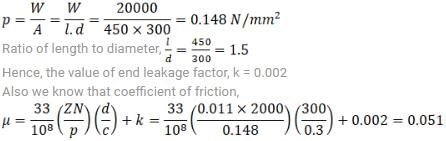
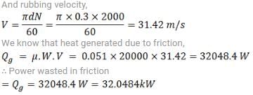
l = 450 mm; c = 0.30 mm ; Z = 0.011 kg/m-s
We know that, bearing pressur
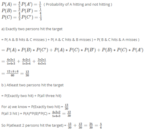
A, B and C shoots to hit a target. If A hits the target 4 times in 5 trials, B hits in 3 times in 4 trials and C hits it 2 times in 3 trials. What is the probability that the target is hit by at least 2 persons?- a)5/6
- b)4/5
- c)3/4
- d)2/3
Correct answer is option 'A'. Can you explain this answer?
a)
5/6
b)
4/5
c)
3/4
d)
2/3

|
Mrinalini Sen answered |
Match the following:
a) Drop forging i-material is only upset
b) Machine forging ii-repeated hammer blows
c) Press forging iii-carried out manually
d) Upset forging iv-squeezing action
e) Smith forging v-metal gripped & pressure applied at heated end- a)A-i B-ii C-iii D-iv E-v
- b)A-ii B-i C-iv D-v E-iii
- c)A-iv B-ii C-v D-iii E-i
- d)A-iii B-ii C-i D-iv E-v
Correct answer is option 'B'. Can you explain this answer?
Match the following:
a) Drop forging i-material is only upset
b) Machine forging ii-repeated hammer blows
c) Press forging iii-carried out manually
d) Upset forging iv-squeezing action
e) Smith forging v-metal gripped & pressure applied at heated end
a) Drop forging i-material is only upset
b) Machine forging ii-repeated hammer blows
c) Press forging iii-carried out manually
d) Upset forging iv-squeezing action
e) Smith forging v-metal gripped & pressure applied at heated end
a)
A-i B-ii C-iii D-iv E-v
b)
A-ii B-i C-iv D-v E-iii
c)
A-iv B-ii C-v D-iii E-i
d)
A-iii B-ii C-i D-iv E-v
|
|
Anagha Chopra answered |
In Drop forging repeated hammer blows, for machine forging material is only upset, in press forging squeezing action takes place.
Consider the following statements
1. In a kinematic inversion, the relative motions between links of the mechanism changes as different
links are made t h e frame by turns.
2. An ellipt ical trammel is a mechanism with three prismatic pairs and one revolute pair. Which of the
statements given above is/are correct?- a)1 only
- b)2 only
- c)Both 1 and 2
- d)Neither 1 nor 2
Correct answer is option 'D'. Can you explain this answer?
Consider the following statements
1. In a kinematic inversion, the relative motions between links of the mechanism changes as different
links are made t h e frame by turns.
2. An ellipt ical trammel is a mechanism with three prismatic pairs and one revolute pair. Which of the
statements given above is/are correct?
1. In a kinematic inversion, the relative motions between links of the mechanism changes as different
links are made t h e frame by turns.
2. An ellipt ical trammel is a mechanism with three prismatic pairs and one revolute pair. Which of the
statements given above is/are correct?
a)
1 only
b)
2 only
c)
Both 1 and 2
d)
Neither 1 nor 2
|
|
Sankar Dasgupta answered |
T hrough the process of inversion the relative motions between the various links is not changed in any manner but their absolute mot ions may be changed drastically.
Elliptical t rammels hav e t wo sliding pairs and two turning pairs. It is an instrum ent used for drawing ellipse.
Elliptical t rammels hav e t wo sliding pairs and two turning pairs. It is an instrum ent used for drawing ellipse.
During a certain reversible process, for a closed system, the entropy of system increases by 4 kJ/K. If the process occurs at a constant temperature of 500 K, the heat input to the system will be- a)2000 kJ
- b)1500 kJ
- c) 2500 kJ
- d)1000 kJ
Correct answer is option 'A'. Can you explain this answer?
a)
2000 kJ
b)
1500 kJ
c)
2500 kJ
d)
1000 kJ
|
|
Shruti Bose answered |
Understanding the Problem
In a reversible process for a closed system, we are given the following data:
- Entropy change (ΔS) = 4 kJ/K
- Temperature (T) = 500 K
We need to determine the heat input (Q) to the system.
Using the Entropy Change Formula
In thermodynamics, the relationship between heat transfer and entropy change at constant temperature is given by:
- ΔS = Q/T
Where:
- ΔS is the change in entropy
- Q is the heat added to the system
- T is the absolute temperature
Calculating the Heat Input
Rearranging the formula to solve for Q gives:
- Q = ΔS * T
Now, substituting the known values:
- Q = 4 kJ/K * 500 K
Performing the Calculation
- Q = 2000 kJ
Conclusion
Thus, the heat input to the system is:
- Option A: 2000 kJ
This result indicates that the system absorbs 2000 kJ of heat to achieve the specified increase in entropy during the reversible process at a constant temperature of 500 K.
Which condition of Rankine cycle has highest efficiency when operating between same pressure limits?- a)Superheated cycle
- b)Regenerative cycle
- c)Reheat cycle
- d) Saturated cycle
Correct answer is option 'B'. Can you explain this answer?
Which condition of Rankine cycle has highest efficiency when operating between same pressure limits?
a)
Superheated cycle
b)
Regenerative cycle
c)
Reheat cycle
d)
Saturated cycle
|
|
Raghav Saini answered |
The efficiency of ideal regenerative cycle is exactly equal to the corresponding Carnot cycle. Hence it is maximum.
Chapter doubts & questions for Practice Test: Full Length - GATE Mechanical (ME) Mock Test Series 2026 2025 is part of Mechanical Engineering exam preparation. The chapters have been prepared according to the Mechanical Engineering exam syllabus. The Chapter doubts & questions, notes, tests & MCQs are made for Mechanical Engineering 2025 Exam. Find important definitions, questions, notes, meanings, examples, exercises, MCQs and online tests here.
Chapter doubts & questions of Practice Test: Full Length - GATE Mechanical (ME) Mock Test Series 2026 in English & Hindi are available as part of Mechanical Engineering exam.
Download more important topics, notes, lectures and mock test series for Mechanical Engineering Exam by signing up for free.
GATE Mechanical (ME) Mock Test Series 2026
30 docs|220 tests
|
|
© EduRev
|
Education Revolution
|


|


Signup to see your scores
go up
within 7 days!
within 7 days!
Takes less than 10 seconds to signup