


All Exams >
Mechanical Engineering >
GATE Mechanical (ME) Mock Test Series 2026 >
All Questions
All questions of Design of Machine Elements for Mechanical Engineering Exam
In thick film hydrodynamic journal bearings, the coefficient of friction
- a) Increases with increases in load
- b) is independent of load
- c) Decreases with increase in load
- d) may increase or decrease with increase in load
Correct answer is option 'C'. Can you explain this answer?
In thick film hydrodynamic journal bearings, the coefficient of friction
a)
Increases with increases in loadb)
is independent of load c)
Decreases with increase in loadd)
may increase or decrease with increase in load |
|
Nisha Singh answered |
Explanation:
Thick film hydrodynamic journal bearings are used to support rotating shafts in various mechanical systems. These bearings work on the principle of hydrodynamic lubrication, where a thin film of lubricant is formed between the journal and the bearing surface due to the relative motion between them.
Coefficient of friction is a measure of the resistance to sliding between two surfaces in contact. In hydrodynamic journal bearings, the coefficient of friction is influenced by various factors such as load, speed, viscosity of the lubricant, surface roughness, and the geometry of the bearing.
Effect of Load on Coefficient of Friction:
- As the load on the bearing increases, the pressure on the lubricant film also increases. This causes the thickness of the lubricant film to decrease, which in turn increases the contact area between the journal and the bearing surface.
- Due to the increased contact area, the shearing forces acting on the lubricant also increase. This leads to an increase in the frictional resistance between the two surfaces, resulting in an increase in the coefficient of friction.
However, this effect is only observed up to a certain limit. Beyond this limit, the thickness of the lubricant film becomes too thin to support the load and the bearing enters into a mixed or boundary lubrication regime. In this regime, the coefficient of friction may increase or decrease depending on the lubricant properties and the surface roughness of the bearing.
Therefore, the correct option is C) Decreases with increase in load, up to a certain limit.
Conclusion:
In thick film hydrodynamic journal bearings, the coefficient of friction initially decreases with an increase in load due to the formation of a thicker lubricant film. However, beyond a certain limit, the lubricant film becomes too thin to support the load and the bearing enters into a mixed or boundary lubrication regime, where the coefficient of friction may increase or decrease depending on various factors.

Which one of the following statements is NOT true of rolling contact bearing? - a)The bearing characteristic number is given by ZN/p where Z is the absolute viscosity of the lubricant, N is the shaft speed and p is the bearing pressure.
- b)Inner race of a radial ball bearing has an interference fit with the shaft and rotates along with it
- c)Outer race of the bearing has an interference fit with bearing housing and does not rotate
- d)In some cases, the inner race is stationary and outer race rotates
Correct answer is option 'D'. Can you explain this answer?
Which one of the following statements is NOT true of rolling contact bearing?
a)
The bearing characteristic number is given by ZN/p where Z is the absolute viscosity of the lubricant, N is the shaft speed and p is the bearing pressure.
b)
Inner race of a radial ball bearing has an interference fit with the shaft and rotates along with it
c)
Outer race of the bearing has an interference fit with bearing housing and does not rotate
d)
In some cases, the inner race is stationary and outer race rotates
|
|
Lavanya Menon answered |
-The term rolling contact bearings refers to the wide variety of bearings that use spherical balls or some other type of roller between the stationary and the moving elements. • The most common type of bearing supports a rotating shaft, resisting purely radial loads or a combination of radial and axial (thrust) loads.
-Roller bearings are used in all main shaft and auxiliary drive shaft applications to support pure radial load, and allow for axial shaft elongation due to temperature changes with no additional load effect on the bearing.
In three ball bearing identified as SKF 2015, 3115 and 4215 - a)Bore is common but width is increasing
- b)Outer diameter is common but bore is increasing
- c)Width is common but outer diameter is decreasing
- d)Bore is common but outer diameter is decreasing
Correct answer is option 'A'. Can you explain this answer?
In three ball bearing identified as
SKF 2015, 3115 and 4215
a)
Bore is common but width is increasing
b)
Outer diameter is common but bore is increasing
c)
Width is common but outer diameter is decreasing
d)
Bore is common but outer diameter is decreasing
|
|
Dipika Bose answered |
According to ISO plan for dimension series bearings are provided with two digit numbers. The first number indicates the width series 8, 0, 1, 2, 3, 4, 5 and 6 in order of increasing width. The second number indicate diameter series 7, 8, 9, 0, 1, 2, 3, and 4 in order of ascending outer diameter of bearing. Thus bearing number SKF 2015, 3115 and 4215 shows bearings belonging to different series with 75 mm bore diameter but width is increasing. SKF 2015, 3115 and 4215 shows width is increasing ascending outer diameter of bearing same bore diameter 75 mm. (i.e. 15 × 5)
A spur gear transmitting power is connected to the shaft with a key of rectangular section. The type (s) of stresses developed in the key is fare. - a)Shear stress alone
- b)bearing stress alone
- c)Both shear and bearing stresses
- d)shearing, bearing and bending stresses.
Correct answer is option 'C'. Can you explain this answer?
A spur gear transmitting power is connected to the shaft with a key of rectangular section. The type (s) of stresses developed in the key is fare.
a)
Shear stress alone
b)
bearing stress alone
c)
Both shear and bearing stresses
d)
shearing, bearing and bending stresses.
|
|
Pranjal Menon answered |
Key develops both shear and bearing stresses.
A square key of side d/4 is to be fitted on a shaft of diameter d and in the hub of a pulley. If the material of the key and shaft is same and the two are to be equally strong in shear, what is the length of the key? - a)πd/2
- b)2πd/3
- c)3πd/4
- d)4πd/5
Correct answer is option 'A'. Can you explain this answer?
A square key of side d/4 is to be fitted on a shaft of diameter d and in the hub of a pulley. If the material of the key and shaft is same and the two are to be equally strong in shear, what is the length of the key?
a)
πd/2
b)
2πd/3
c)
3πd/4
d)
4πd/5
|
|
Lavanya Menon answered |
The length of the key will be 
Consider the following statements: 1. A stub tooth has a working depth larger than that of a full-depth tooth.2. The path of contact for involute gears is an arc of a circle. Which of the statements given above is/are correct? - a)Only 1
- b)Only 2
- c)Both 1 and 2
- d)Neither 1 nor 2
Correct answer is option 'D'. Can you explain this answer?
Consider the following statements:
1. A stub tooth has a working depth larger than that of a full-depth tooth.
2. The path of contact for involute gears is an arc of a circle.
Which of the statements given above is/are correct?
a)
Only 1
b)
Only 2
c)
Both 1 and 2
d)
Neither 1 nor 2
|
|
Divya Banerjee answered |
1. A stub tooth has a working depth lower than that of a full-depth tooth.
2. The path of contact for involute gears is a line.
Which one of the following is a criterion in the design of hydrodynamic journal bearings? - a)Sommerfeld number
- b)rating life
- c)Specific dynamic capacity
- d)Rotation factor
Correct answer is option 'A'. Can you explain this answer?
Which one of the following is a criterion in the design of hydrodynamic journal bearings?
a)
Sommerfeld number
b)
rating life
c)
Specific dynamic capacity
d)
Rotation factor

|
Partho Singh answered |
Criterion in the design of hydrodynamic journal bearings
The hydrodynamic journal bearing is a type of bearing that operates on the principle of hydrodynamic lubrication, where a film of lubricating fluid is created between the journal and the bearing surfaces. This film of lubricant helps to reduce friction, prevent wear, and provide smooth and reliable operation. In the design of hydrodynamic journal bearings, several criteria are considered, but the most important criterion is the Sommerfeld number.
Sommerfeld number
The Sommerfeld number, also known as the Sommerfeld parameter or bearing number, is a dimensionless parameter that represents the ratio of the load-carrying capacity of the bearing to the viscous dissipation of the lubricant. It is defined as the ratio of the product of the journal diameter, rotational speed, and the viscosity of the lubricant to the product of the load and the dynamic viscosity of the lubricant.
The Sommerfeld number is given by the equation:
Sommerfeld number = (d * N * μ) / (P * μ')
Where:
- d is the journal diameter
- N is the rotational speed
- μ is the viscosity of the lubricant
- P is the load
- μ' is the dynamic viscosity of the lubricant
Significance of the Sommerfeld number
The Sommerfeld number is a crucial criterion in the design of hydrodynamic journal bearings because it determines the stability and performance of the bearing. A low Sommerfeld number indicates a high load-carrying capacity and good lubrication, while a high Sommerfeld number suggests poor lubrication and potential bearing failure.
When designing a hydrodynamic journal bearing, the Sommerfeld number is used to ensure that the bearing operates within an acceptable range. If the Sommerfeld number is too low, it may result in excessive wear and failure of the bearing due to insufficient lubrication. On the other hand, if the Sommerfeld number is too high, it may lead to excessive heat generation and reduced bearing life.
Other criteria in the design of hydrodynamic journal bearings
While the Sommerfeld number is the most important criterion, other factors are also considered in the design of hydrodynamic journal bearings, including:
- Rating life: This criterion represents the expected operating life of the bearing under specified conditions. It takes into account factors such as load, speed, lubrication, and temperature.
- Specific dynamic capacity: This criterion refers to the load-carrying capacity of the bearing per unit area of the bearing surface. It indicates the ability of the bearing to support the applied load without excessive deformation or failure.
- Rotation factor: This criterion represents the ratio of the circumferential speed of the journal to the speed of sound in the lubricant. It is used to ensure that the bearing operates within the limits of the lubricant film speed, as excessive speeds can lead to film breakdown and bearing failure.
In conclusion, while there are several criteria in the design of hydrodynamic journal bearings, the Sommerfeld number is the most important one. It determines the load-carrying capacity and lubrication performance of the bearing. The other criteria, such as rating life, specific dynamic capacity, and rotation factor, are also considered to ensure the overall performance and reliability of the bearing.
In spur gears, the circle on which the involute is generated is called the - a)Pitch circle
- b)clearance circle
- c)Base c ircle
- d)adden dum circle
Correct answer is option 'A'. Can you explain this answer?
In spur gears, the circle on which the involute is generated is called the
a)
Pitch circle
b)
clearance circle
c)
Base c ircle
d)
adden dum circle
|
|
Gayatri Dasgupta answered |
Pitch Circle in Spur Gears
Pitch circle is an important term used in the context of spur gears. It refers to the imaginary circle that intersects with the teeth of the gear. The pitch circle is used to calculate the gear ratio, tooth profile, and other important parameters of the gear. In this article, we will discuss the pitch circle in detail.
Definition
The pitch circle is the circle on which the involute gear tooth profile is based. It is an imaginary circle that intersects with the teeth of the gear. The diameter of the pitch circle is the reference diameter of the gear, which is used to calculate the gear ratio, tooth profile, and other important parameters of the gear.
Importance
The pitch circle is an important concept in gear design because it helps to determine the geometry of the gear teeth. The distance between the centers of two gears is called the pitch distance, and it is equal to the sum of the pitch diameters of the two gears. The pitch circle is also used to calculate the pitch angle, which is the angle between the tangent to the pitch circle and the axis of the gear.
Calculation
The pitch circle diameter (P.C.D) is calculated using the following formula:
P.C.D = N x M
where N is the number of teeth on the gear, and M is the module (size) of the gear.
The pitch circle diameter is also related to the outside diameter (O.D.) and the root diameter (R.D.) of the gear:
O.D. = P.C.D + 2 x addendum
R.D. = P.C.D - 2 x dedendum
where addendum is the distance between the pitch circle and the top of the tooth, and dedendum is the distance between the pitch circle and the bottom of the tooth.
Conclusion
In conclusion, the pitch circle is an imaginary circle that intersects with the teeth of the gear. It is an important concept in gear design because it helps to determine the geometry of the gear teeth. The pitch circle diameter is used to calculate the gear ratio, tooth profile, and other important parameters of the gear.
When σ and Young's Modulus of Elasticity E remain constant, the energy absorbing capacity of part subject to dynamic forces, is a function of its - a)Length
- b)cross-section
- c)volume
- d)none of the above
Correct answer is option 'C'. Can you explain this answer?
When σ and Young's Modulus of Elasticity E remain constant, the energy absorbing capacity of part subject to dynamic forces, is a function of its
a)
Length
b)
cross-section
c)
volume
d)
none of the above
|
|
Amar Nambiar answered |
Strain energy is given by,
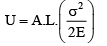
∴U is proportional to (A.L.) which is volume. Also, since U is a function of σ2 , that portion of the part which is prone to high localised will absorb a high amount of energy, making it vulnerable to failure. Such a part, therefore, is designed to have such a contour that, when it is subjected to time-varying or impact loads or others types of dynamic forces, the part absorbs or less uniform stress distribution along the whole length of the part is ensured.
Which one of the following statements relating to belt drives is correct? - a)The rotational speeds of the pulleys are directly proportional to their diameters
- b)The length of the crossed belt increases as the sum of the diameters of the pulleys increases
- c)The crowning of the pulleys is done to make the drive sturdy
- d)The slip increases the velocity ratio
Correct answer is option 'B'. Can you explain this answer?
Which one of the following statements relating to belt drives is correct?
a)
The rotational speeds of the pulleys are directly proportional to their diameters
b)
The length of the crossed belt increases as the sum of the diameters of the pulleys increases
c)
The crowning of the pulleys is done to make the drive sturdy
d)
The slip increases the velocity ratio
|
|
Sanskriti Basu answered |
Statement: The length of the crossed belt increases as the sum of the diameters of the pulleys increases.
Explanation:
Belt Drives:
Belt drives are a type of power transmission mechanism used to transmit power from one shaft to another. They consist of a belt that is wrapped around two pulleys. The power is transferred through the tension in the belt, which causes friction between the belt and the pulleys.
Length of the Crossed Belt:
The length of the crossed belt refers to the total length of the belt that is in contact with the pulleys. It is important to know the length of the crossed belt in order to properly design and select a belt for a specific application.
Relation with the Sum of Diameters:
The length of the crossed belt is directly related to the sum of the diameters of the pulleys. As the sum of the diameters increases, the length of the crossed belt also increases.
Reasoning:
When a belt is wrapped around two pulleys, the length of the belt is determined by the distance it travels along the circumference of the pulleys. The distance traveled by the belt is directly proportional to the sum of the diameters of the pulleys.
To visualize this, imagine two pulleys of different sizes. If the belt is wrapped around the smaller pulley, it will travel a shorter distance compared to if it is wrapped around the larger pulley. Therefore, the length of the crossed belt increases as the sum of the diameters of the pulleys increases.
Example:
Let's consider an example to further illustrate this concept. Suppose we have two pulleys with diameters of 10 cm and 20 cm. The sum of the diameters is 30 cm. If we wrap a belt around these pulleys, the length of the crossed belt will be greater compared to if we had two pulleys with diameters of 5 cm and 10 cm, where the sum of the diameters is 15 cm.
Conclusion:
In conclusion, the statement "The length of the crossed belt increases as the sum of the diameters of the pulleys increases" is correct. The length of the crossed belt is directly proportional to the sum of the diameters of the pulleys in a belt drive system.
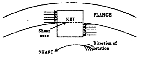
A key connecting a flange coupling to a shaft is likely to fail in - a)Shear
- b)tension
- c)torsion
- d)bending
Correct answer is option 'A'. Can you explain this answer?
A key connecting a flange coupling to a shaft is likely to fail in
a)
Shear
b)
tension
c)
torsion
d)
bending
|
|
Hrishikesh Chakraborty answered |
Shear is the dominant stress on the key
A flywheel has a mass of 300 kg and a radius of gyration of 1m. It is given a spin of 100 r.p.m about its horizontal axis. The whole assembly rotates about a vertical axis at 6 rad/sec. The gyroscopic couple experienced will be - a)3π kNm
- b)6π kNm
- c)180π kNm
- d)360π kNm
Correct answer is option 'B'. Can you explain this answer?
A flywheel has a mass of 300 kg and a radius of gyration of 1m. It is given a spin of 100 r.p.m about its horizontal axis. The whole assembly rotates about a vertical axis at 6 rad/sec. The gyroscopic couple experienced will be
a)
3π kNm
b)
6π kNm
c)
180π kNm
d)
360π kNm

|
Anshu Kumar answered |
Given:
Mass of the flywheel, m = 300 kg
Radius of gyration, k = 1 m
Spin speed about horizontal axis, ω₁ = 100 rpm
Rotation speed about vertical axis, ω₂ = 6 rad/sec
To find:
The gyroscopic couple experienced by the flywheel.
Solution:
Step 1: Calculate the spin angular velocity
The spin angular velocity, ω₁, is given in rpm. To convert it to rad/sec, we use the following formula:
ω = (2π/60) * ω₁
Substituting the given value of ω₁, we get:
ω = (2π/60) * 100
ω = (π/30) * 100
ω = (10π/3) rad/sec
Step 2: Calculate the moment of inertia (I)
The moment of inertia of the flywheel can be calculated using the formula:
I = mk²
Substituting the given values of mass (m) and radius of gyration (k), we get:
I = 300 * 1²
I = 300 kg·m²
Step 3: Calculate the gyroscopic couple (C)
The gyroscopic couple (C) can be calculated using the formula:
C = I * ω₁ * ω₂
Substituting the values of moment of inertia (I), spin angular velocity (ω₁), and rotation speed (ω₂), we get:
C = 300 * (10π/3) * 6
C = 6000π N·m
C ≈ 18850 N·m
Step 4: Convert the gyroscopic couple to kNm
To convert the gyroscopic couple from N·m to kNm, we divide by 1000:
C = 18850 N·m
C ≈ 18.85 kNm
Therefore, the gyroscopic couple experienced by the flywheel is approximately 18.85 kNm.
The percentage improvement in power capacity of a flat belt drive, when the wrap angle at the driving pulley is increased from 150° to 210° by an idler arrangement for a friction coefficient of 0.3, is- a)25.21
- b)33.92
- c)40.17
- d)67.85
Correct answer is option 'D'. Can you explain this answer?
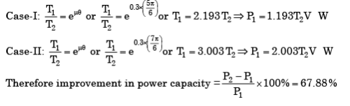
The percentage improvement in power capacity of a flat belt drive, when the wrap angle at the driving pulley is increased from 150° to 210° by an idler arrangement for a friction coefficient of 0.3, is
a)
25.21
b)
33.92
c)
40.17
d)
67.85
|
|
Anuj Chauhan answered |
We know that Power transmitted (P) = ( T1 −T2 ) .v W
Which one of the following statements is correct? While designing a parallel sunk key it is assumed that the distribution of force along the length of the key - a)Varies linearly
- b)is uniform throughout
- c)varies exponentially, being more at the torque input end
- d)varies exponentially, being less at torque output end
Correct answer is option 'C'. Can you explain this answer?
Which one of the following statements is correct?
While designing a parallel sunk key it is assumed that the distribution of force along the length of the key
a)
Varies linearly
b)
is uniform throughout
c)
varies exponentially, being more at the torque input end
d)
varies exponentially, being less at torque output end
|
|
Dipika Kulkarni answered |
Parallel sunk key. The parallel sunk keys may be of rectangular or square section uniform in width and thickness throughout. It may be noted that a parallel key is a taperless and is used where the pulley, gear or other mating piece is required to slide along the shaft. In designing a key, forces due to fit of the key are neglected and it is assumed that the distribution of forces along the length of key is uniform.
Line joining Syt (yield strength of the material) on mean stress axis and Se (endurance limit of the component) on stress amplitude axis is called as _____- a) Goodman line
- b) Soderberg line
- c) Gerber line
- d) None of the above
Correct answer is option 'B'. Can you explain this answer?
Line joining Syt (yield strength of the material) on mean stress axis and Se (endurance limit of the component) on stress amplitude axis is called as _____
a)
Goodman line
b)
Soderberg line
c)
Gerber line
d)
None of the above

|
Anirban Khanna answered |
Soderberg line:
- Line joining Syt (yield strength of the material) on mean stress axis and Se (endurance limit of the component) on stress amplitude axis is called as Soderberg line. This line is used when yielding defines failure.
- (σm / Syt) + (σa / Se) = (1 / Nf) is the equation for Soderberg line.
In a Belt drive, if the pulley diameter is doubled keeping the tension and belt width constant, then it will be necessary to - a)Increase the key length
- b)increase the key depth
- c)Increase the key width
- d)decrease the key length
Correct answer is option 'C'. Can you explain this answer?
In a Belt drive, if the pulley diameter is doubled keeping the tension and belt width constant, then it will be necessary to
a)
Increase the key length
b)
increase the key depth
c)
Increase the key width
d)
decrease the key length
|
|
Anjali Sengupta answered |
Due to twice increase in diameter of pulley, torque on key is double and has to be resisted by key width. Length can't be increased as belt width is same.
A 1.5 kW motor is running at 1440 rev/min. It is to be connected to a stirrer running at 36 rev /min. The gearing arrangement suitable for this application is - a)Differential gear
- b)helical gear
- c)Spur gear
- d)worm gear
Correct answer is option 'D'. Can you explain this answer?
A 1.5 kW motor is running at 1440 rev/min. It is to be connected to a stirrer running at 36 rev /min. The gearing arrangement suitable for this application is
a)
Differential gear
b)
helical gear
c)
Spur gear
d)
worm gear
|
|
Avik Ghosh answered |
speed reduction = 1440/36 = 40
In an oil-lubricated journal bearing, coefficient of friction between the journal and the bearing. - a)Remains constant at all speeds.
- b)is minimum at zero speed and increases monotonically with increase in speed.
- c)is maximum at zero speed and decreases monotonically with increase in speed.
- d)becomes minimum at an optimum speed and then increases with further increase in speed.
Correct answer is option 'D'. Can you explain this answer?
In an oil-lubricated journal bearing, coefficient of friction between the journal and the bearing.
a)
Remains constant at all speeds.
b)
is minimum at zero speed and increases monotonically with increase in speed.
c)
is maximum at zero speed and decreases monotonically with increase in speed.
d)
becomes minimum at an optimum speed and then increases with further increase in speed.
|
|
Ayush Chawla answered |
Friction in Oil-Lubricated Journal Bearing
Friction is a significant factor in the performance of oil-lubricated journal bearings. The coefficient of friction between the journal and the bearing is affected by various factors, such as the speed of the journal, the viscosity of the lubricant, the surface roughness of the journal and the bearing, and the pressure distribution in the lubricating film. The coefficient of friction can be defined as the ratio of the frictional force between the journal and the bearing to the normal force between them.
Behavior of Coefficient of Friction with Speed
The behavior of the coefficient of friction with speed depends on the operating conditions and the design of the bearing. Generally, the coefficient of friction decreases with an increase in speed due to the following reasons:
- The viscosity of the lubricant decreases with an increase in temperature, and the shear rate increases with an increase in speed, leading to a decrease in the viscosity of the lubricant.
- The pressure distribution in the lubricating film changes with an increase in speed, and the pressure peaks shift towards the center of the bearing, reducing the frictional force between the journal and the bearing.
However, the coefficient of friction may not always decrease with an increase in speed and may reach a minimum value at an optimum speed and then increase with further increase in speed. This behavior is due to the following reasons:
- At low speeds, the lubricating film is thick, and the pressure distribution is more uniform, resulting in a high coefficient of friction.
- At high speeds, the lubricating film is thin, and the pressure distribution is non-uniform, resulting in a high coefficient of friction.
- At an optimum speed, the lubricating film is neither too thick nor too thin, and the pressure distribution is more uniform, resulting in a low coefficient of friction.
Conclusion
In conclusion, the coefficient of friction between the journal and the bearing in an oil-lubricated journal bearing becomes minimum at an optimum speed and then increases with further increase in speed due to the changes in the viscosity of the lubricant and the pressure distribution in the lubricating film.
The yield strength of a steel shaft is twice its endurance limit. Which of the following torque fluctuation represent the most critical situation according to Soderberg criterion? - a)-T to +T
- b)-T/2 to +T
- c)0 to +T
- d)+T/2 to +T
Correct answer is option 'A'. Can you explain this answer?
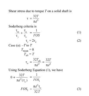
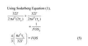
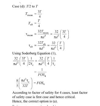
The yield strength of a steel shaft is twice its endurance limit. Which of the following torque fluctuation represent the most critical situation according to Soderberg criterion?
a)
-T to +T
b)
-T/2 to +T
c)
0 to +T
d)
+T/2 to +T

|
Shreya Choudhary answered |
Ans.
Large speed reductions (greater than 20) in one stage of a gear train are possible through - a)Spur gearing
- b)Worm gearing
- c)Bevel gearing
- d)Helical gearing
Correct answer is option 'B'. Can you explain this answer?
Large speed reductions (greater than 20) in one stage of a gear train are possible through
a)
Spur gearing
b)
Worm gearing
c)
Bevel gearing
d)
Helical gearing
|
|
Raj Kumar answered |
Worm Gearing for Large Speed Reductions
Worm gearing is a type of gear system that is used to achieve large speed reductions in a single stage. This is possible due to the unique design of the worm gear, which consists of a worm and a worm wheel. The worm is a screw-like gear that engages with the teeth of the worm wheel, which is a cylindrical gear with teeth around its circumference.
Advantages of Worm Gearing
There are several advantages of using worm gearing for large speed reductions:
1. High Reduction Ratio: Worm gears can achieve high reduction ratios of up to 300:1 in a single stage, which makes them ideal for applications that require large speed reductions.
2. Self-Locking: Worm gears are self-locking, which means that they can hold a load in place without the need for a brake or other locking mechanism.
3. Compact Design: Worm gears have a compact design that allows them to be used in applications where space is limited.
4. Smooth Operation: Worm gears have a smooth operation due to the rolling contact between the worm and the worm wheel, which reduces friction and wear.
5. High Efficiency: Worm gears are highly efficient, with efficiencies of up to 90%, which makes them ideal for applications where energy efficiency is important.
Applications of Worm Gearing
Worm gearing is used in a wide range of applications, including:
1. Conveyor systems
2. Elevators
3. Packaging machinery
4. Material handling equipment
5. Printing presses
Conclusion
In conclusion, worm gearing is an excellent choice for achieving large speed reductions in a single stage. Its self-locking, compact design, smooth operation, high efficiency, and wide range of applications make it a popular choice for engineers and designers.
The S-N curve for steel becomes asymptotic nearly at - a)103 cycles
- b)104 cycles
- c)106 cycles
- d)109 cycles
Correct answer is option 'C'. Can you explain this answer?
The S-N curve for steel becomes asymptotic nearly at
a)
103 cycles
b)
104 cycles
c)
106 cycles
d)
109 cycles
|
|
Neha Choudhury answered |
S-N for steel becomes a sympetric at 10^6 cycles.Hence, the correct option is (c)
In a cotter joint, the width of the cotter at the centre is 50 mm and its thickness is 12 mm. The load acting on the cotter is 60 kN. What is the shearing stress developed in the cotter? - a)120N/mm2
- b)100N/mm2
- c)75/mm2
- d)50N/mm2
Correct answer is option 'D'. Can you explain this answer?
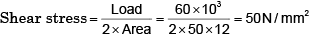
In a cotter joint, the width of the cotter at the centre is 50 mm and its thickness is 12 mm. The load acting on the cotter is 60 kN. What is the shearing stress developed in the cotter?
a)
120N/mm2
b)
100N/mm2
c)
75/mm2
d)
50N/mm2
|
|
Sagarika Dey answered |
It is a case of double shear.
Assertion (A): A cotter joint is used to rigidly connect two coaxial rods carrying tensile load.Reason (R): Taper in the cotter is provided to facilitate its removal when it fails due to shear. - a)Both A and R are true and R is the correct explanation of A
- b)Both A and R are true but R is NOT the correct explanation of A
- c)A is true but R is false
- d)A is false but R is true
Correct answer is option 'B'. Can you explain this answer?
Assertion (A): A cotter joint is used to rigidly connect two coaxial rods carrying tensile load.
Reason (R): Taper in the cotter is provided to facilitate its removal when it fails due to shear.
a)
Both A and R are true and R is the correct explanation of A
b)
Both A and R are true but R is NOT the correct explanation of A
c)
A is true but R is false
d)
A is false but R is true
|
|
Athul Desai answered |
A cotter is a flat wedge shaped piece of rectangular cross-section and its width is tapered (either on one side or both sides) from one end to another for an easy adjustment. The taper varies from 1 in 48 to 1 in 24 and it may be increased up to 1 in 8, if a locking device is provided. The locking device may be a taper pin or a set screw used on the lower end of the cotter. The cotter is usually made of mild steel or wrought iron. A cotter joint is a temporary fastening and is used to connect rigidly two co-axial rods or bars which are subjected to axial tensile or compressive forces.
A clutch has outer and inner diameters 100 mm and 40 mm respectively. Assuming a uniform pressure of 2 MPa and coefficient of friction of liner material 0.4, the torque carrying capacity of the clutch is - a)148 Nm
- b)196 Nm
- c)372 Nm
- d)490 Nm
Correct answer is option 'B'. Can you explain this answer?
A clutch has outer and inner diameters 100 mm and 40 mm respectively. Assuming a uniform pressure of 2 MPa and coefficient of friction of liner material 0.4, the torque carrying capacity of the clutch is
a)
148 Nm
b)
196 Nm
c)
372 Nm
d)
490 Nm
|
|
Nandini Basak answered |
Given data:
- Outer diameter of clutch (D1) = 100 mm
- Inner diameter of clutch (D2) = 40 mm
- Uniform pressure (P) = 2 MPa
- Coefficient of friction (μ) = 0.4
To calculate the torque carrying capacity of the clutch, we can use the formula:
T = (π/2) * (D1^2 - D2^2) * P * μ
Let's break down the solution into steps:
Step 1: Convert the diameters from millimeters to meters
- D1 = 100 mm = 0.1 m
- D2 = 40 mm = 0.04 m
Step 2: Calculate the torque carrying capacity using the formula
- T = (π/2) * (0.1^2 - 0.04^2) * 2e6 * 0.4
- T = (π/2) * (0.01 - 0.0016) * 2e6 * 0.4
- T = (π/2) * 0.0084 * 2e6 * 0.4
- T = 0.0084 * π * 2e6 * 0.4
- T = 2680832 Nmm
Step 3: Convert the torque from Newton-millimeters to Newton-meters
- 1 Nm = 1 Nmm / 1000
- T = 2680832 / 1000
- T ≈ 2680.832 Nm
Therefore, the torque carrying capacity of the clutch is approximately 2680.832 Nm, which is closest to option B (196 Nm).
In conclusion, option B is the correct answer.
Consider the following design considerations: 1. Tensile failure2. Creep failure3. Bearing failure4.Shearing failure5. Bending failureThe design of the pin of a rocker arm of an I.C. engine is based on - a)1, 2 and 4
- b)1, 3 and 4
- c)2, 3 and 5
- d)3, 4 and 5.
Correct answer is option 'D'. Can you explain this answer?
Consider the following design considerations:
1. Tensile failure
2. Creep failure
3. Bearing failure
4.Shearing failure
5. Bending failure
The design of the pin of a rocker arm of an I.C. engine is based on
a)
1, 2 and 4
b)
1, 3 and 4
c)
2, 3 and 5
d)
3, 4 and 5.
|
|
Mansi Kulkarni answered |
Understanding the Design Considerations for Rocker Arm Pins
When designing the pin of a rocker arm in an internal combustion (I.C.) engine, several failure modes should be considered. The correct answer, option 'D', focuses on bearing failure, shearing failure, and bending failure. Here’s a detailed breakdown:
Tensile Failure
- This failure mode occurs when the material experiences excessive tensile stress.
- While important, tensile failure is not the primary concern for the pin in this context.
Creep Failure
- Creep failure happens over time under constant stress at elevated temperatures.
- Although creep is relevant in high-temperature applications, it is less critical for rocker arm pins, which operate under variable loads and temperatures.
Bearing Failure
- Bearing failure is crucial since the pin acts as a pivot point in the rocker arm assembly.
- Proper design must account for the loads transferred through the pin to prevent excessive wear or seizure.
Shearing Failure
- Shearing failure occurs when the pin is subjected to lateral forces that cause it to slide or fail along its cross-section.
- This type of failure is significant in rocker arms due to the dynamic forces at play.
Bending Failure
- Bending failure arises when the pin is subjected to moments causing it to bend beyond its elastic limit.
- Given the rocker arm's motion and the forces it experiences, ensuring the pin can withstand bending stresses is vital for longevity and performance.
Conclusion
Selecting option 'D' (bearing, shearing, and bending failures) emphasizes the critical design aspects that will ensure the pin's durability and functionality in an I.C. engine rocker arm. Proper consideration of these factors leads to safer and more efficient engine operation.
Which one of the following is correct? A hydrodynamic slider bearing develops load bearing capacity mainly because of - a)Slider velocity
- b)wedge shaped oil film
- c)Oil compressibility
- d)oil viscosity
Correct answer is option 'B'. Can you explain this answer?
Which one of the following is correct?
A hydrodynamic slider bearing develops load bearing capacity mainly because of
a)
Slider velocity
b)
wedge shaped oil film
c)
Oil compressibility
d)
oil viscosity
|
|
Dipika Bose answered |
A hydrodynamic slider bearing develops load bearing capacity mainly because of wedge shaped oil film.
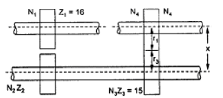
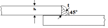
Two plates are joined together by means of single transverse and double parallel fillet welds as shown in figure given above. If the size of fillet is 5 mm and allowable shear load per mm is 300 N, what is the approximate length of each parallel fillet? 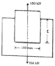
- a)150 mm
- b)200 mm
- c)250 mm
- d)300 mm
Correct answer is option 'B'. Can you explain this answer?
Two plates are joined together by means of single transverse and double parallel fillet welds as shown in figure given above. If the size of fillet is 5 mm and allowable shear load per mm is 300 N, what is the approximate length of each parallel fillet?
a)
150 mm
b)
200 mm
c)
250 mm
d)
300 mm
|
|
Rajeev Menon answered |
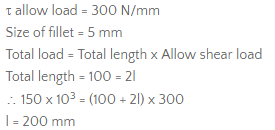
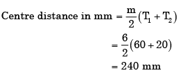
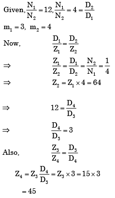
The overall gear ratio in a 2 stage speed reduction gear box (with all spur gears) is 12. The input and output shafts of the gear box are collinear. The countershaft which is parallel to the input and output shafts has a gear (Z2 teeth) and pinion (Z3 = 15 teeth) to mesh with pinion (Z1 = 16 teeth) on the input shaft and gear (Z4 teeth) on the output shaft respectively. It was decided to use a gear ratio of 4 with 3 module in the first stage and 4 module in the second stage. Que: Z2 and Z4 are - a)64 and 45
- b)45 and 64
- c)48 and 60
- d)60 and 48
Correct answer is option 'A'. Can you explain this answer?
The overall gear ratio in a 2 stage speed reduction gear box (with all spur gears) is 12. The input and output shafts of the gear box are collinear. The countershaft which is parallel to the input and output shafts has a gear (Z2 teeth) and pinion (Z3 = 15 teeth) to mesh with pinion (Z1 = 16 teeth) on the input shaft and gear (Z4 teeth) on the output shaft respectively. It was decided to use a gear ratio of 4 with 3 module in the first stage and 4 module in the second stage.
Que: Z2 and Z4 are
a)
64 and 45
b)
45 and 64
c)
48 and 60
d)
60 and 48
|
|
Raj Kumar answered |
The ratio of tension on the tight side to that on the slack side in a flat belt drive is - a)Proportional to the product of coefficient of friction and lap angle
- b)An exponential function of the product of coefficient of friction and lap angle.
- c)Proportional to the lap angle
- d)Proportional to the coefficient of friction
Correct answer is option 'B'. Can you explain this answer?
The ratio of tension on the tight side to that on the slack side in a flat belt drive is
a)
Proportional to the product of coefficient of friction and lap angle
b)
An exponential function of the product of coefficient of friction and lap angle.
c)
Proportional to the lap angle
d)
Proportional to the coefficient of friction
|
|
Rajat Basu answered |

Which key is preferred for the condition where a large amount of impact torque is to be transmitted in both direction of rotation? - a)Woodruff key
- b)Feather key
- c)Gib-head key
- d)Tangent key
Correct answer is option 'D'. Can you explain this answer?
Which key is preferred for the condition where a large amount of impact torque is to be transmitted in both direction of rotation?
a)
Woodruff key
b)
Feather key
c)
Gib-head key
d)
Tangent key
|
|
Rajeev Sharma answered |
Tangent key withstands torsion in one direction only that's why two tangent keys are used opposite when the shaft is subjected to high impact torque.
Gearing contact is which one of the following? - a)Sliding contact
- b)Sliding contact, only rolling at pitch point
- c)Rolling contact
- d)Rolling and sliding at each point of contact
Correct answer is option 'B'. Can you explain this answer?
Gearing contact is which one of the following?
a)
Sliding contact
b)
Sliding contact, only rolling at pitch point
c)
Rolling contact
d)
Rolling and sliding at each point of contact
|
|
Akshara Rane answered |
When pair of teeth touch at the pitch point ,they have for the instant pure rolling action. At any other position they have the slidingaction.
Total slip will Occur in a belt drive when - a)Angle of rest is zero
- b)Angle of creep is zero
- c)Angle of rest is greater than angle of creep
- d)Angle of creep is greater than angle of rest
Correct answer is option 'A'. Can you explain this answer?
Total slip will Occur in a belt drive when
a)
Angle of rest is zero
b)
Angle of creep is zero
c)
Angle of rest is greater than angle of creep
d)
Angle of creep is greater than angle of rest
|
|
Asha Basu answered |
Explanation:
- Belt drives are used to transmit power from one shaft to another.
- When the belt is in motion, it tends to slide over the pulleys due to the frictional force between the belt and the pulley surface.
- The amount of slip that occurs in a belt drive depends on the angle of rest and angle of creep.
- The angle of rest is the maximum angle at which the belt will remain in contact with the pulley surface without slipping, when the pulley is at rest.
- The angle of creep is the maximum angle at which the belt will remain in contact with the pulley surface without slipping, when the pulley is in motion.
- Total slip refers to the difference between the linear distance traveled by the belt and the distance traveled by the pulley surface during a complete revolution of the pulley.
- Total slip occurs when the belt slips on the pulley surface due to insufficient frictional force.
Option A:
- If the angle of rest is zero, it means that the belt will remain in contact with the pulley surface even when the pulley is at rest.
- This indicates that there will be sufficient frictional force between the belt and the pulley surface to prevent slip.
- Therefore, in this case, total slip will not occur in the belt drive.
Option B:
- If the angle of creep is zero, it means that the belt will remain in contact with the pulley surface even when the pulley is in motion.
- This indicates that there will be sufficient frictional force between the belt and the pulley surface to prevent slip.
- However, this does not guarantee that total slip will not occur in the belt drive, as there may be other factors such as belt tension, pulley diameter, and belt material that can affect slip.
Option C and D:
- If the angle of rest is greater than the angle of creep, it means that the belt will slip on the pulley surface when the pulley is in motion, as the angle of creep is the maximum angle at which the belt can remain in contact with the pulley surface without slipping.
- Similarly, if the angle of creep is greater than the angle of rest, it means that the belt will slip on the pulley surface even when the pulley is at rest, as the angle of rest is the maximum angle at which the belt can remain in contact with the pulley surface without slipping.
- In both these cases, there will be insufficient frictional force between the belt and the pulley surface to prevent slip, and total slip will occur in the belt drive.
A pulley is connected to a power transmission shaft of diameter d by means of a rectangular sunk key of width wand length ‘l’. The width of the key is taken as d/4. For full power transmission, the shearing strength of the key is equal to the torsional shearing strength of the shaft. The ratio of the length of the key to the diameter of the shaft (l/d) is - a)π/4
- b)π/√2
- c)π/2
- d)π
Correct answer is option 'C'. Can you explain this answer?
A pulley is connected to a power transmission shaft of diameter d by means of a rectangular sunk key of width wand length ‘l’. The width of the key is taken as d/4. For full power transmission, the shearing strength of the key is equal to the torsional shearing strength of the shaft. The ratio of the length of the key to the diameter of the shaft (l/d) is
a)
π/4
b)
π/√2
c)
π/2
d)
π
|
|
Sai Reddy answered |
To determine the ratio of the length of the key (l) to the diameter of the shaft (d), we need to compare the shearing strengths of the key and the shaft.
1. Shearing Strength of the Key:
The shearing strength of a rectangular sunk key can be calculated using the formula:
Shearing Strength of Key = (Width of Key * Length of Key * Shear Stress) / (Factor of Safety)
Given that the width of the key is d/4, we can substitute this value into the formula:
Shearing Strength of Key = ((d/4) * l * Shear Stress) / (Factor of Safety)
2. Shearing Strength of the Shaft:
The shearing strength of a shaft can be calculated using the formula:
Shearing Strength of Shaft = (π/16) * (d^3) * Shear Stress
3. Equating the Shearing Strengths:
Since the shearing strength of the key is equal to the shearing strength of the shaft for full power transmission, we can set the two equations equal to each other:
((d/4) * l * Shear Stress) / (Factor of Safety) = (π/16) * (d^3) * Shear Stress
4. Simplifying the Equation:
To simplify the equation, we can cancel out the shear stress terms:
(d/4) * l / (Factor of Safety) = (π/16) * (d^3)
5. Determining the Ratio (l/d):
To find the ratio of l/d, we can rearrange the equation:
l/d = (π/16) * (d^2) / ((d/4) * (Factor of Safety))
Simplifying further:
l/d = (4π/16) * (d^2) / (d * (Factor of Safety))
l/d = (π/4) * (d/Factor of Safety)
Since the width of the key is taken as d/4, we can substitute this value into the equation:
l/d = (π/4) * (Width of Key/Factor of Safety)
Therefore, the ratio of l/d is given by (π/4), which is equal to option 'C'.
In a band brake the ratio of tight side band tension to the tension on theslack side is 3. If the angle of overlap of band on the drum is 180° the coefficient of friction required between drum and the band is- a)0.20
- b)0.25
- c)0.30
- d)0.35
Correct answer is option 'D'. Can you explain this answer?
In a band brake the ratio of tight side band tension to the tension on theslack side is 3. If the angle of overlap of band on the drum is 180° the coefficient of friction required between drum and the band is
a)
0.20
b)
0.25
c)
0.30
d)
0.35
|
|
Soumya Basak answered |
Band Brake and its Working Principle
A band brake is a type of brake that uses a flexible band to wrap around a rotating drum to stop the motion. The band is tightened around the drum by applying tension to one end of the band. The tension on the other end of the band is kept slack. When the brake is applied, the friction between the band and the drum generates a force that resists the motion of the drum.
Calculating the Coefficient of Friction
Given data:
- Ratio of tight side band tension to slack side = 3
- Angle of overlap of band on drum = 180 degrees
Formula:
Coefficient of friction = (Ratio of tension - 1) / (2 x sin(angle of overlap))
Substituting the values, we get:
Coefficient of friction = (3 - 1) / (2 x sin(180)) = 0.35
Therefore, the correct answer is option 'D' (0.35).
Explanation:
The ratio of tight side band tension to slack side is 3, which means the tight side tension is three times greater than the slack side tension. The angle of overlap of the band on the drum is 180 degrees, which means the band wraps around the drum completely. The coefficient of friction is calculated using the formula, which takes into account the ratio of tension and the angle of overlap. Substituting the values, we get the coefficient of friction as 0.35. This means that the friction between the band and the drum must be 0.35 to stop the motion of the drum effectively.
Gearing contact is which one of the following? - a)Sliding contact
- b)Sliding contact, only rolling at pitch point
- c)Rolling contact
- d)Rolling and sliding at each point of contact
Correct answer is option 'B'. Can you explain this answer?
Gearing contact is which one of the following?
a)
Sliding contact
b)
Sliding contact, only rolling at pitch point
c)
Rolling contact
d)
Rolling and sliding at each point of contact
|
|
Dishani Desai answered |
When pair of teeth touch at the pitch point ,they have for the instant pure rolling action. At any other position they have the slidingaction.
In involute gears the pressure angle is - a)Dependent on the size of teeth
- b)dependent on the size of gears
- c)Always constant
- d)always variable
Correct answer is option 'C'. Can you explain this answer?
In involute gears the pressure angle is
a)
Dependent on the size of teeth
b)
dependent on the size of gears
c)
Always constant
d)
always variable
|
|
Kritika Joshi answered |
The pressure angle is always constant in involute gears.
A single parallel fillet weld of total length L and weld size h subjected to a tensile load P, will have what design stress? - a)Tensile and equal to P/0.707Lh
- b)Tensile and equal to P/Lh
- c)Shear and equal to P/0.707Lh
- d)Shear and equal to P/Lh
Correct answer is option 'C'. Can you explain this answer?
A single parallel fillet weld of total length L and weld size h subjected to a tensile load P, will have what design stress?
a)
Tensile and equal to P/0.707Lh
b)
Tensile and equal to P/Lh
c)
Shear and equal to P/0.707Lh
d)
Shear and equal to P/Lh
|
|
Rajat Khanna answered |
Sources of power loss in a chain drive are given below: 1. Friction between chain and sprocket teeth. 2. Overcoming the chain stiffness. 3. Overcoming the friction in shaft bearing. 4. Frictional resistance to the motion of the chain in air or lubricant. The correct sequence of descending order of power loss due to these sources is - a)1,2,3,4
- b)1,2,4,3
- c)2,1,3,4
- d)2,1,4,3
Correct answer is option 'A'. Can you explain this answer?
Sources of power loss in a chain drive are given below:
1. Friction between chain and sprocket teeth.
2. Overcoming the chain stiffness.
3. Overcoming the friction in shaft bearing.
4. Frictional resistance to the motion of the chain in air or lubricant.
The correct sequence of descending order of power loss due to these sources is
a)
1,2,3,4
b)
1,2,4,3
c)
2,1,3,4
d)
2,1,4,3
|
|
Sandeep Sengupta answered |
Power loss in descending order takes place as 1, 2 3 and 4.
Assertion (A ): In a short centre open-belt drive, an idler pulley is used to maintain the belt tension and to increase the angle of contact on the smaller pulley. Reason (R): An idler pulley is free to rotate on its axis and is put on the slack side of the belt. - a)Both A and R are individually true and R is the correct explanation of A
- b)Both A and R are individually true but R is not the correct explanation of A
- c)A is true but R is false
- d)A is false but R is true
Correct answer is option 'A'. Can you explain this answer?
Assertion (A ): In a short centre open-belt drive, an idler pulley is used to maintain the belt tension and to increase the angle of contact on the smaller pulley.
Reason (R): An idler pulley is free to rotate on its axis and is put on the slack side of the belt.
a)
Both A and R are individually true and R is the correct explanation of A
b)
Both A and R are individually true but R is not the correct explanation of A
c)
A is true but R is false
d)
A is false but R is true
|
|
Rajat Khanna answered |
Both A and R are true, and R provides correct explanation for A.
Consider the following statements: 1. Endurance strength of a component is not affected by its surface finish and notch sensitivity of the material.2. For ferrous materials like steel, S-N curve becomes asymptotic at 106 cycles.Which of the statements given above is/are correct? - a)1 only
- b)2 only
- c)Both 1 and 2
- d)Neither 1 nor 2
Correct answer is option 'B'. Can you explain this answer?
Consider the following statements:
1. Endurance strength of a component is not affected by its surface finish and notch sensitivity of the material.
2. For ferrous materials like steel, S-N curve becomes asymptotic at 106 cycles.
Which of the statements given above is/are correct?
a)
1 only
b)
2 only
c)
Both 1 and 2
d)
Neither 1 nor 2
|
|
Nayanika Yadav answered |
Explanation:
1. Endurance strength of a component is not affected by its surface finish and notch sensitivity of the material:
- The statement is incorrect. The endurance strength of a component can be significantly affected by its surface finish and the material's notch sensitivity.
- Surface finish can introduce stress concentrations, which can lead to premature failure of a component.
- Notch sensitivity refers to how susceptible a material is to stress concentration effects, with highly sensitive materials experiencing a greater decrease in endurance strength.
2. For ferrous materials like steel, S-N curve becomes asymptotic at 10^6 cycles:
- The statement is correct. In the case of ferrous materials like steel, the S-N curve typically becomes asymptotic at around 10^6 cycles.
- This means that beyond this point, the material experiences a much lower rate of decrease in endurance strength with increasing cycles, indicating a higher fatigue life.
Therefore, the correct answer is option B - 2 only.
A cotter joint is used when no relative motion is permitted between the rods joined by the cotter. It is capable of transmitting - a)Twisting moment
- b)an axial tensile as well as compressive load
- c)The bending moment
- d)only compressive axial load
Correct answer is option 'B'. Can you explain this answer?
A cotter joint is used when no relative motion is permitted between the rods joined by the cotter. It is capable of transmitting
a)
Twisting moment
b)
an axial tensile as well as compressive load
c)
The bending moment
d)
only compressive axial load

|
Baishali Bajaj answered |
It is used in connecting rods. Now, the connecting rod is subjected to tensile as well as compressive load.
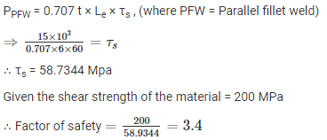
Assertion (A): When the coupler of a turn buckle is turned in one direction both the connecting rods either move closer or move away from each other depending upon the direction of rotation of the coupler. Reason (R): A turn buckle is used to connect two round rods subjected to tensile loading and requiring subsequent adjustment for tightening or loosening. - a)Both A and R are individually true and R is the correct explanation of A
- b)Both A and R are individually true but R is not the correct explanation of A
- c)A is true but R is false
- d)A is false but R is true
Correct answer is option 'B'. Can you explain this answer?
Assertion (A): When the coupler of a turn buckle is turned in one direction both the connecting rods either move closer or move away from each other depending upon the direction of rotation of the coupler.
Reason (R): A turn buckle is used to connect two round rods subjected to tensile loading and requiring subsequent adjustment for tightening or loosening.
a)
Both A and R are individually true and R is the correct explanation of A
b)
Both A and R are individually true but R is not the correct explanation of A
c)
A is true but R is false
d)
A is false but R is true
|
|
Anjali Sengupta answered |
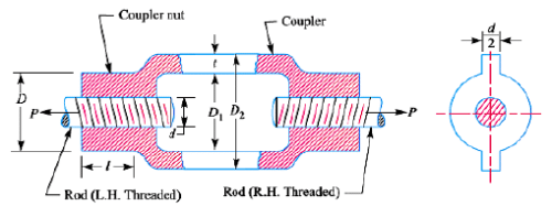
A sliding contact bearing is operating under stable condition. The pressure developed in oil film is p when the journal rotates at N r.p.m. The dynamic viscosity of lubricant is μ and effective coefficient of friction between bearing and journal of diameter D is f. Which one of the following statements is correct for the bearing? - a)f is directly proportional to μ and p
- b)f is directly proportional to μ and N
- c)f is inversely proportional to p and f
- d)f is directly proportional to μ and inversely proportional to N
Correct answer is option 'B'. Can you explain this answer?
A sliding contact bearing is operating under stable condition. The pressure developed in oil film is p when the journal rotates at N r.p.m. The dynamic viscosity of lubricant is μ and effective coefficient of friction between bearing and journal of diameter D is f. Which one of the following statements is correct for the bearing?
a)
f is directly proportional to μ and p
b)
f is directly proportional to μ and N
c)
f is inversely proportional to p and f
d)
f is directly proportional to μ and inversely proportional to N
|
|
Anshul Sharma answered |

In a 6 × 20 wire rope, No.6 indicates the - a)diameter of the wire rope in mm
- b)Number of strands in the wire rope
- c)Number of wires
- d)Gauge number of the wire
Correct answer is option 'B'. Can you explain this answer?
In a 6 × 20 wire rope, No.6 indicates the
a)
diameter of the wire rope in mm
b)
Number of strands in the wire rope
c)
Number of wires
d)
Gauge number of the wire

|
Divya Kulkarni answered |
Explanation:
In a 6 x 20 wire rope, the number 6 indicates the number of strands in the wire rope.
Wire Rope Construction:
A wire rope is constructed by combining multiple strands of wires together. Each strand consists of multiple wires twisted together. The construction of a wire rope is denoted by two numbers separated by an 'x', such as 6 x 20.
- The first number (6 in this case) represents the number of strands in the wire rope.
- The second number (20 in this case) represents the number of wires in each strand.
Interpretation of the Numbers:
To interpret the numbers correctly, let's consider the example of a 6 x 20 wire rope.
- The number of strands (6) indicates that there are 6 individual strands twisted together to form the wire rope. These strands are typically helically laid around a central core.
- Each strand consists of a certain number of wires, which are twisted together. In this case, there are 20 wires in each strand. These wires are typically laid in a helical pattern around a central core within each individual strand.
Significance of the Number of Strands:
The number of strands in a wire rope affects its strength, flexibility, and resistance to wear. Generally, a wire rope with a higher number of strands provides better flexibility and resistance to wear. It also tends to have a higher breaking strength compared to a wire rope with a lower number of strands.
Conclusion:
In summary, in a 6 x 20 wire rope, the number 6 indicates the number of strands in the wire rope. The higher the number of strands, the greater the flexibility, resistance to wear, and breaking strength of the wire rope.
Which one of the following pairs is not correctly matched? - a)Positive drive .... Belt drive
- b)High velocity ratio .... Worm gearing
- c)To connect non-parallel and non- intersecting shafts .... Spiral gearing.
- d)Diminished noise and smooth operation .... Helical gears.
Correct answer is option 'A'. Can you explain this answer?
Which one of the following pairs is not correctly matched?
a)
Positive drive .... Belt drive
b)
High velocity ratio .... Worm gearing
c)
To connect non-parallel and non- intersecting shafts .... Spiral gearing.
d)
Diminished noise and smooth operation .... Helical gears.
|
|
Anirban Khanna answered |
CORRECT OPTION IS (A).
Due to slip present, the velocity ration will not remain constant and hence, belt drive is not a positive drive
Due to slip present, the velocity ration will not remain constant and hence, belt drive is not a positive drive
Assertion (A): Uniform-strength bolts are used for resisting impact loads.Reason (R): The area of cross-section of the threaded and unthreaded parts is made equal. - a)Both A and R are individually true and R is the correct explanation of A
- b)Both A and R are individually true but R is not the correct explanation of A
- c)A is true but R is false
- d)A is false but R is true
Correct answer is option 'C'. Can you explain this answer?
Assertion (A): Uniform-strength bolts are used for resisting impact loads.
Reason (R): The area of cross-section of the threaded and unthreaded parts is made equal.
a)
Both A and R are individually true and R is the correct explanation of A
b)
Both A and R are individually true but R is not the correct explanation of A
c)
A is true but R is false
d)
A is false but R is true
|
|
Keerthana Joshi answered |
Assertion (A): Uniform-strength bolts are used for resisting impact loads.
Reason (R): The area of cross-section of the threaded and unthreaded parts is made equal.
The correct answer is option C: A is true but R is false.
Explanation:
Uniform-strength bolts are designed to have the same strength in both the threaded and unthreaded sections. This allows for a more balanced distribution of load along the length of the bolt, which helps in resisting impact loads. However, the reason given for this assertion is not correct.
The area of cross-section of the threaded and unthreaded parts of a bolt is not necessarily made equal in uniform-strength bolts. In fact, the threaded section of the bolt is usually weaker than the unthreaded section due to the reduction in cross-sectional area caused by the threads. This reduction in cross-sectional area results in a decrease in the strength of the threaded section compared to the unthreaded section.
The main reason for using uniform-strength bolts in applications where impact loads are expected is to prevent stress concentration. Stress concentration occurs when there is a change in cross-sectional area along the length of a component, such as a bolt. This change in cross-sectional area can lead to high localized stresses, which can cause the component to fail under impact loads.
Uniform-strength bolts are designed to have a gradual transition from the unthreaded section to the threaded section, resulting in a more uniform distribution of stress along the length of the bolt. This helps to reduce stress concentration and improve the overall strength of the bolt under impact loads.
In conclusion, while uniform-strength bolts are indeed used for resisting impact loads, the reason given for this assertion is incorrect. The area of cross-section of the threaded and unthreaded parts of a bolt is not made equal in uniform-strength bolts.
Chapter doubts & questions for Design of Machine Elements - GATE Mechanical (ME) Mock Test Series 2026 2025 is part of Mechanical Engineering exam preparation. The chapters have been prepared according to the Mechanical Engineering exam syllabus. The Chapter doubts & questions, notes, tests & MCQs are made for Mechanical Engineering 2025 Exam. Find important definitions, questions, notes, meanings, examples, exercises, MCQs and online tests here.
Chapter doubts & questions of Design of Machine Elements - GATE Mechanical (ME) Mock Test Series 2026 in English & Hindi are available as part of Mechanical Engineering exam.
Download more important topics, notes, lectures and mock test series for Mechanical Engineering Exam by signing up for free.
GATE Mechanical (ME) Mock Test Series 2026
30 docs|220 tests
|
|
© EduRev
|
Education Revolution
|


|


Signup to see your scores
go up
within 7 days!
within 7 days!
Takes less than 10 seconds to signup