


All Exams >
Electrical Engineering (EE) >
Analog and Digital Electronics >
All Questions
All questions of Operational Amplifier for Electrical Engineering (EE) Exam
The other name for Miller Circuit is- a)Non-Inverting Integrator
- b)Inverting Integrator
- c)Non-Inverting Differentiator
- d)Inverting Differentiator
Correct answer is option 'B'. Can you explain this answer?
The other name for Miller Circuit is
a)
Non-Inverting Integrator
b)
Inverting Integrator
c)
Non-Inverting Differentiator
d)
Inverting Differentiator
|
|
Sanvi Kapoor answered |
Miller Circuit is also called Inverting integrator.

What are the units of slew rate?- a)Second/Volt
- b)Volt/second
- c)It is a ratio, no units
- d)Ohm/second
Correct answer is option 'B'. Can you explain this answer?
What are the units of slew rate?
a)
Second/Volt
b)
Volt/second
c)
It is a ratio, no units
d)
Ohm/second

|
Ishita Patel answered |
These units are obtained from the definition of the term slew rate.
Consider an inverting amplifier circuit designed using an op amp and two resistors, R1 = 10 kΩ and R2 = 1 MΩ. If the op amp is specified to have an input bias current of 100 nA and an input offset current of 10 nA, find the output dc offset voltage resulting.- a)0.1 mV
- b)1 mV
- c)10 mV
- d)100 mV
Correct answer is option 'D'. Can you explain this answer?
Consider an inverting amplifier circuit designed using an op amp and two resistors, R1 = 10 kΩ and R2 = 1 MΩ. If the op amp is specified to have an input bias current of 100 nA and an input offset current of 10 nA, find the output dc offset voltage resulting.
a)
0.1 mV
b)
1 mV
c)
10 mV
d)
100 mV

|
Manisha Chavan answered |
Use the mathematical definition of bias current and offset current.
The expression for the differentiator time constant is- a)CR
- b)1/CR
- c)R/C
- d)C/R
Correct answer is option 'A'. Can you explain this answer?
The expression for the differentiator time constant is
a)
CR
b)
1/CR
c)
R/C
d)
C/R

|
Sahana Chavan answered |
Standard mathematical expression for the time constant for the differentiators.

The phase in the integrator and differentiator circuit respectively are- a)+90 degrees and +90 degrees
- b)-90 degrees and -90 degrees
- c)-90 degrees and +90 degrees
- d)+90 degrees and -90 degrees
Correct answer is option 'D'. Can you explain this answer?
The phase in the integrator and differentiator circuit respectively are
a)
+90 degrees and +90 degrees
b)
-90 degrees and -90 degrees
c)
-90 degrees and +90 degrees
d)
+90 degrees and -90 degrees
|
|
Sarita Yadav answered |
These are the characteristics of the integrators and differentiators circuits respectively.
For an ideal negative feedback configuration which of the following is true?- a)There is a virtual open circuit between the input terminals
- b)The closed loop gain for a negative feedback does not depend only on the external parameters
- c)There is a virtual short circuit between the input terminals
- d)There is a virtual ground at the negative input terminal
Correct answer is option 'C'. Can you explain this answer?
For an ideal negative feedback configuration which of the following is true?
a)
There is a virtual open circuit between the input terminals
b)
The closed loop gain for a negative feedback does not depend only on the external parameters
c)
There is a virtual short circuit between the input terminals
d)
There is a virtual ground at the negative input terminal

|
Arshiya Dasgupta answered |
There is always a virtual short circuit in this type of case. There will be a virtual ground if and only if one of the terminals is grounded.
Consider an inverting amplifier with a nominal gain of 1000 constructed from an op amp with an input offset voltage of 3 mV and with output saturation levels of ±10 V. What is (approximately) the peak sine-wave input signal that can be applied without output clipping?- a)7 mV
- b)10 mV
- c)13 mV
- d)9mV
Correct answer is option 'A'. Can you explain this answer?
Consider an inverting amplifier with a nominal gain of 1000 constructed from an op amp with an input offset voltage of 3 mV and with output saturation levels of ±10 V. What is (approximately) the peak sine-wave input signal that can be applied without output clipping?
a)
7 mV
b)
10 mV
c)
13 mV
d)
9mV

|
Pankaj Rane answered |
The maximum that can be sent without clipping is 10V – 1000 X 3mV or 7V.
What is the minimum number of pins for a dual operational amplifier IC package?- a)4
- b)6
- c)8
- d)10
Correct answer is option 'C'. Can you explain this answer?
What is the minimum number of pins for a dual operational amplifier IC package?
a)
4
b)
6
c)
8
d)
10

|
Varun Banerjee answered |
The minimum no of pins required by dual-op-amp is 8. Each op-amp has 2 input terminals(4 pins) and one output terminal(2 pins). Another 2 pins are required for power.
The negative feedback causes- a)The voltage between the two input terminals to the very small, ideally zero
- b)The voltage between the two input resistance very high, ideally infinite
- c)Current flow through the positive input terminal and no current flows through the negative input terminal
- d)Both a and c
Correct answer is option 'A'. Can you explain this answer?
The negative feedback causes
a)
The voltage between the two input terminals to the very small, ideally zero
b)
The voltage between the two input resistance very high, ideally infinite
c)
Current flow through the positive input terminal and no current flows through the negative input terminal
d)
Both a and c
|
|
Sanvi Kapoor answered |
Ideally the input terminals are at the same potential but in real practice there is a very small potential between the two terminals.
In an inverting op-amp circuit for which the gain is −4 V/V and the total resistance used is 100 kΩ. Then the value of R1 and R2 (negative feedback)- a)R1 = 20KΩ and R1 = 80KΩ
- b) R1 = 80KΩ and R1 = 20KΩ
- c) R1 = 40KΩ and R1 = 60KΩ
- d) R1 = 50KΩ and R1 = 50KΩ
Correct answer is option 'A'. Can you explain this answer?
In an inverting op-amp circuit for which the gain is −4 V/V and the total resistance used is 100 kΩ. Then the value of R1 and R2 (negative feedback)
a)
R1 = 20KΩ and R1 = 80KΩ
b)
R1 = 80KΩ and R1 = 20KΩ
c)
R1 = 40KΩ and R1 = 60KΩ
d)
R1 = 50KΩ and R1 = 50KΩ

|
Bibek Mukherjee answered |
Solve R1 + R2 = 100
R2/R1 = 4 for R1 and R2 respectively.
R2/R1 = 4 for R1 and R2 respectively.
An op amp having a 106-dB gain at dc and a single-pole frequency response with ft = 2 MHz is used to design a non-inverting amplifier with nominal dc gain of 100. The 3-dB frequency of the closed-loop gain is- a)10 kHz
- b)20 kHz
- c)30 kHz
- d)40 kHz
Correct answer is option 'B'. Can you explain this answer?
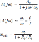
An op amp having a 106-dB gain at dc and a single-pole frequency response with ft = 2 MHz is used to design a non-inverting amplifier with nominal dc gain of 100. The 3-dB frequency of the closed-loop gain is
a)
10 kHz
b)
20 kHz
c)
30 kHz
d)
40 kHz
|
|
Nishtha Chauhan answered |
The given problem involves designing a non-inverting amplifier using an operational amplifier (op amp) with specific characteristics. The op amp has a gain of 106 dB at dc (direct current) and a single-pole frequency response with a transition frequency (ft) of 2 MHz. We are required to determine the 3-dB frequency of the closed-loop gain for the amplifier.
Understanding the Problem:
To solve this problem, we need to consider the characteristics of the op amp and the properties of the non-inverting amplifier configuration. The closed-loop gain of the non-inverting amplifier is determined by the feedback resistor (Rf) and the input resistor (Rin).
Non-Inverting Amplifier Configuration:
In a non-inverting amplifier, the input signal is applied to the non-inverting terminal of the op amp, and the feedback resistor is connected between the output and the inverting terminal. The input resistor is connected between the non-inverting terminal and the input signal source.
Determining the Closed-Loop Gain:
The closed-loop gain (Av) of a non-inverting amplifier is given by the formula:
Av = 1 + (Rf/Rin)
In this problem, the desired nominal dc gain is 100, so we can write:
100 = 1 + (Rf/Rin)
Determining the Gain at the 3-dB Frequency:
The transition frequency (ft) of the op amp is the frequency at which the gain starts to roll off. In a single-pole response, the gain decreases at a rate of -20 dB per decade after the transition frequency.
The 3-dB frequency (f3dB) is the frequency at which the gain drops by 3 dB (half-power point). We can determine the 3-dB frequency using the formula:
f3dB = ft / Av
Substituting the given values:
f3dB = 2 MHz / 100
Solving the Equation:
Now, we can solve the equation to find the value of f3dB:
f3dB = 20 kHz
Therefore, the 3-dB frequency of the closed-loop gain is 20 kHz, which corresponds to option B.
The non-inverting closed loop configuration features a high resistance. Therefore in many cases unity gain follower called buffer amplifier is often used to- a)Connect a high resistance source to high resistance load
- b)Connect low resistance source to low resistance load
- c)Connect low resistance source to a high resistance source
- d)Connect high resistance source to a low resistance load
Correct answer is option 'D'. Can you explain this answer?
The non-inverting closed loop configuration features a high resistance. Therefore in many cases unity gain follower called buffer amplifier is often used to
a)
Connect a high resistance source to high resistance load
b)
Connect low resistance source to low resistance load
c)
Connect low resistance source to a high resistance source
d)
Connect high resistance source to a low resistance load

|
Saptarshi Nair answered |
Buffer amplifiers are required to connect a high resistance load to a low input resistance output.
Express the input voltages v1 and v2 in terms of differential input (vd) and common-mode input(vc). Given v2 > v2.- a)Vd = V1 – V2, Vc = 0.5(V1 + V2)
- b)Vd = V2 – V1, Vc = V1 + V2
- c) Vd = V1 – V2, Vc = V1 + V2
- d) Vd = V2 – V1, Vc = 0.5(V1 + V2)
Correct answer is option 'D'. Can you explain this answer?
Express the input voltages v1 and v2 in terms of differential input (vd) and common-mode input(vc). Given v2 > v2.
a)
Vd = V1 – V2, Vc = 0.5(V1 + V2)
b)
Vd = V2 – V1, Vc = V1 + V2
c)
Vd = V1 – V2, Vc = V1 + V2
d)
Vd = V2 – V1, Vc = 0.5(V1 + V2)

|
Neha Basak answered |
This is the correct mathematical representation.
What is the minimum number of terminals required in an IC package containing four operational amplifiers (quad op amps)?- a)12
- b)13
- c)14
- d)15
Correct answer is option 'C'. Can you explain this answer?
What is the minimum number of terminals required in an IC package containing four operational amplifiers (quad op amps)?
a)
12
b)
13
c)
14
d)
15
|
|
Varun Banerjee answered |
The minimum no of pins required by dual-op-amp is 8. Each op-amp has 2 input terminals(4 pins) and one output terminal(2 pins). Another 2 pins are required for power.
Similarly, The minimum no of pins required by dual-op-amp is 14: 4*2 + 4*1 + 2 = 14.
Similarly, The minimum no of pins required by dual-op-amp is 14: 4*2 + 4*1 + 2 = 14.
Which of the following is not a terminal for the operational amplifier?- a)Inverting terminal
- b)Non-inverting terminal
- c)Output terminal
- d)None of the mentioned
Correct answer is option 'D'. Can you explain this answer?
Which of the following is not a terminal for the operational amplifier?
a)
Inverting terminal
b)
Non-inverting terminal
c)
Output terminal
d)
None of the mentioned
|
|
Bijoy Mehta answered |
Introduction:
An operational amplifier (op-amp) is an integrated circuit that is widely used in electronic circuits. It has three main terminals: the inverting terminal, the non-inverting terminal, and the output terminal. These terminals play crucial roles in determining the behavior and functionality of the op-amp.
Inverting Terminal:
- The inverting terminal, also known as the negative input terminal, is denoted by a negative sign (-).
- When a voltage is applied to this terminal, the output voltage of the op-amp is inverted and amplified.
- The inverting terminal is typically used to create an inverting amplifier or a summing amplifier.
Non-inverting Terminal:
- The non-inverting terminal, also known as the positive input terminal, is denoted by a positive sign (+).
- When a voltage is applied to this terminal, the output voltage of the op-amp is non-inverted and amplified.
- The non-inverting terminal is typically used to create a non-inverting amplifier or a voltage follower.
Output Terminal:
- The output terminal is denoted by the symbol "O".
- It is the terminal from which the amplified signal is obtained.
- The output voltage of the op-amp is determined by the voltages present at the inverting and non-inverting terminals.
None of the mentioned:
- The statement "None of the mentioned" is incorrect.
- All three terminals mentioned above are essential and present in an operational amplifier.
- Each terminal serves a specific purpose in the amplification and signal processing functions of the op-amp.
- Therefore, the correct answer to the question is not "None of the mentioned."
Conclusion:
In summary, an operational amplifier has three main terminals: the inverting terminal, the non-inverting terminal, and the output terminal. Each terminal has a unique function in determining the behavior and functionality of the op-amp. Therefore, the correct answer is not "None of the mentioned."
A single-pole model has __________ db/decade roll-off of the gain.- a)-3 db/decade
- b)-6 db/decade
- c)-10 db/decade
- d)-20 db/decade
Correct answer is option 'D'. Can you explain this answer?
A single-pole model has __________ db/decade roll-off of the gain.
a)
-3 db/decade
b)
-6 db/decade
c)
-10 db/decade
d)
-20 db/decade

|
Diya Ahuja answered |
It is a standard characteristic of a single-pole model.

It is required to connect a transducer having an open-circuit voltage of 1 V and a source resistance of 1 MΩ to a load of 1-kΩ resistance. Find the load voltage if the connection is done- a)1 μV and 1 mV respectively
- b)1 mV and 1 V respectively
- c)0.1 μV and 0.1 mV respectively
- d)0.1 mV and 0.1 V respectively
Correct answer is option 'B'. Can you explain this answer?
It is required to connect a transducer having an open-circuit voltage of 1 V and a source resistance of 1 MΩ to a load of 1-kΩ resistance. Find the load voltage if the connection is done
a)
1 μV and 1 mV respectively
b)
1 mV and 1 V respectively
c)
0.1 μV and 0.1 mV respectively
d)
0.1 mV and 0.1 V respectively

|
Sanchita Pillai answered |
When a unity gain follower is uses then input signal is equal to output signal. When connected directly, output signal is given by 1 X 1kΩ/1MΩ or 1mV.
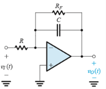
Consider a symmetrical square wave of 20-V peak-to-peak, 0 average, and 2-ms period applied to a Miller integrator. Find the value of the time constant CR such that the triangular waveform at the output has a 20-V peak-to-peak amplitude.- a)0.25ms
- b)0.50ms
- c)2.5ms
- d)5.0ms
Correct answer is option 'B'. Can you explain this answer?
Consider a symmetrical square wave of 20-V peak-to-peak, 0 average, and 2-ms period applied to a Miller integrator. Find the value of the time constant CR such that the triangular waveform at the output has a 20-V peak-to-peak amplitude.
a)
0.25ms
b)
0.50ms
c)
2.5ms
d)
5.0ms
|
|
Arpita Banerjee answered |
According to the question 1/CR = 2.

An internally compensated op amp has a dc open-loop gain of 106 V/V and an AC open-loop gain of 40 dB at 10 kHz. Estimate its gain–bandwidth product and its expected gain at 1 kHz.- a)0.1 MHz and -60 db
- b)10 MHz and -60 db
- c)10 MHz and 60 db
- d)1 MHz and 60 db
Correct answer is option 'D'. Can you explain this answer?
An internally compensated op amp has a dc open-loop gain of 106 V/V and an AC open-loop gain of 40 dB at 10 kHz. Estimate its gain–bandwidth product and its expected gain at 1 kHz.
a)
0.1 MHz and -60 db
b)
10 MHz and -60 db
c)
10 MHz and 60 db
d)
1 MHz and 60 db

|
Rutuja Deshpande answered |
Use the following results.
(Q2 & Q.3) Consider an inverting amplifier with a nominal gain of 1000 constructed from an op amp with an input offset voltage of 3 mV and with output saturation levels of ±10 V. If the effect of VOs(input offset voltage) is nulled at room temperature (250C), how large an input can one now apply if:
Q. The circuit is to operate at a constant temperature?- a) 8.5 mV
- b)9 mV
- c)9.5 mV
- d)10 mV
Correct answer is option 'D'. Can you explain this answer?
(Q2 & Q.3) Consider an inverting amplifier with a nominal gain of 1000 constructed from an op amp with an input offset voltage of 3 mV and with output saturation levels of ±10 V. If the effect of VOs(input offset voltage) is nulled at room temperature (250C), how large an input can one now apply if:
Q. The circuit is to operate at a constant temperature?
Q. The circuit is to operate at a constant temperature?
a)
8.5 mV
b)
9 mV
c)
9.5 mV
d)
10 mV

|
Pranavi Gupta answered |
Explanation: Maximum signal that will not be clipped is 10mV because 10mV X 1000 = 10V.
The expression for the integration frequency is- a)CR
- b)1/CR
- c)R/C
- d)C/R
Correct answer is option 'B'. Can you explain this answer?
The expression for the integration frequency is
a)
CR
b)
1/CR
c)
R/C
d)
C/R

|
Uday Kumar answered |
Standard mathematical expression for the integrator frequency.
An internally compensated op amp is specified to have an open-loop dc gain of 106 dB and a unity gain bandwidth of 3 MHz. Find fb and the open-loop gain at fb.- a)15Hz and 103 db
- b)30Hz and 103 db
- c)15 Hz and 51.5 db
- d)30 Hz and 51.5 db
Correct answer is option 'A'. Can you explain this answer?
An internally compensated op amp is specified to have an open-loop dc gain of 106 dB and a unity gain bandwidth of 3 MHz. Find fb and the open-loop gain at fb.
a)
15Hz and 103 db
b)
30Hz and 103 db
c)
15 Hz and 51.5 db
d)
30 Hz and 51.5 db

|
Navya Sarkar answered |
Use the equations below.
In an ideal op amp the open-loop gain is 103. The op amp is used in a feedback circuit, and the voltages appearing at two of its three signal terminals are measured as v2 = 0V and v3 = 2V where it is assumed that v1 and v2 are input terminals and v3 is the output terminal. The value of the differential (vd) and common-mode (vcm)signal is- a)Vd = 2 mV and vcm = 1 mv
- b) Vd = 2 mV and vcm = -1 mV
- c)Vd = 2 mV and vcm = 2mV
- d)Vd = 2 mV and vcm = -2mV
Correct answer is option 'B'. Can you explain this answer?
In an ideal op amp the open-loop gain is 103. The op amp is used in a feedback circuit, and the voltages appearing at two of its three signal terminals are measured as v2 = 0V and v3 = 2V where it is assumed that v1 and v2 are input terminals and v3 is the output terminal. The value of the differential (vd) and common-mode (vcm)signal is
a)
Vd = 2 mV and vcm = 1 mv
b)
Vd = 2 mV and vcm = -1 mV
c)
Vd = 2 mV and vcm = 2mV
d)
Vd = 2 mV and vcm = -2mV
|
|
Ishita Patel answered |
Vc = 0.5(V1 + V2) and
Vd = V2 – V1.
Vd = V2 – V1.
Which of the following is not true for a voltage follower amplifier?- a)Input voltage is equal to output voltage
- b)Input resistance is infinite and output resistance is zero
- c)It has 100% negative feedback
- d)None of the mentioned
Correct answer is option 'D'. Can you explain this answer?
Which of the following is not true for a voltage follower amplifier?
a)
Input voltage is equal to output voltage
b)
Input resistance is infinite and output resistance is zero
c)
It has 100% negative feedback
d)
None of the mentioned

|
Jaya Yadav answered |
All the statements are false.
Which of the following is not a property of an ideal operational amplifier?- a)Zero input impedance
- b)Infinite bandwidth
- c)Infinite open loop gain
- d)Zero common-mode gain or conversely infinite common mode-rejection.
Correct answer is option 'A'. Can you explain this answer?
Which of the following is not a property of an ideal operational amplifier?
a)
Zero input impedance
b)
Infinite bandwidth
c)
Infinite open loop gain
d)
Zero common-mode gain or conversely infinite common mode-rejection.

|
Bhavya Rane answered |
An ideal operational amplifier does not has a zero input impedance.
You are provided with an ideal op amp and three 10kΩ resistors. Using series and parallel resistor combinations, how many different inverting-amplifier circuit topologies are possible?- a)2
- b)3
- c)4
- d)5
Correct answer is option 'C'. Can you explain this answer?
You are provided with an ideal op amp and three 10kΩ resistors. Using series and parallel resistor combinations, how many different inverting-amplifier circuit topologies are possible?
a)
2
b)
3
c)
4
d)
5
|
|
Athul Banerjee answered |
Resistors. Design a non-inverting amplifier with a gain of 5.
For an ideal operational amplifier (except for the fact that it has finite gain) one set of the value for the input voltages (v2 is the positive terminal v1 is the negative terminal) and output voltage (v0) as determined experimentally is v1= 2.01V, v2=2.00V and v0= -0.99V. Experiment was carried with different values of input and output voltages. Which of the following is not possible considering experimental error?- a)v1= 1.99V, v2= 2.00V, v0 = 1.00V
- b)v1= 1.00V, v2= 1.00V, v0 = 0V
- c)v1= 1.00V, v2= 1.10V, v0 = 10.1V
- d)v1= 0.99V, v2= 2.00V, v0 = 1.00V
Correct answer is option 'D'. Can you explain this answer?
For an ideal operational amplifier (except for the fact that it has finite gain) one set of the value for the input voltages (v2 is the positive terminal v1 is the negative terminal) and output voltage (v0) as determined experimentally is v1= 2.01V, v2=2.00V and v0= -0.99V. Experiment was carried with different values of input and output voltages. Which of the following is not possible considering experimental error?
a)
v1= 1.99V, v2= 2.00V, v0 = 1.00V
b)
v1= 1.00V, v2= 1.00V, v0 = 0V
c)
v1= 1.00V, v2= 1.10V, v0 = 10.1V
d)
v1= 0.99V, v2= 2.00V, v0 = 1.00V

|
Shreya Choudhary answered |
Only option d does not satisfies the mathematical relation between the given quantities.
Operational amplifiers are- a)Differential input and single-ended output type amplifier
- b)Single-ended input and single-ended output type amplifier
- c)Single-ended input and differential output type amplifier
- d)Differential input and differential output type amplifier
Correct answer is option 'A'. Can you explain this answer?
Operational amplifiers are
a)
Differential input and single-ended output type amplifier
b)
Single-ended input and single-ended output type amplifier
c)
Single-ended input and differential output type amplifier
d)
Differential input and differential output type amplifier

|
Anshu Kumar answered |
It is another way to refer to op amps based on its terminal characteristics.
The advantage of a weighted summer operational amplifier is- a)It is capable of summing various input voltages together
- b)Each input signal may be independently adjusted by adjusting the corresponding input resistance
- c)If one needs both sign of a voltage signal then two operational amplifiers are needed
- d)All of the mentioned
Correct answer is option 'D'. Can you explain this answer?
The advantage of a weighted summer operational amplifier is
a)
It is capable of summing various input voltages together
b)
Each input signal may be independently adjusted by adjusting the corresponding input resistance
c)
If one needs both sign of a voltage signal then two operational amplifiers are needed
d)
All of the mentioned
|
|
Saumya Sen answered |
Advantages of Weighted Summer Operational Amplifier:
Advantages:
- Summing Capability: A weighted summer operational amplifier is capable of summing various input voltages together. This is especially useful in applications where multiple signals need to be combined or added together.
- Independent Adjustment: Each input signal may be independently adjusted by adjusting the corresponding input resistance. This level of control allows for precise tuning of each input signal, ensuring accurate summation.
- Sign of Voltage Signal: If one needs both the positive and negative aspects of a voltage signal, two operational amplifiers are typically needed. However, with a weighted summer operational amplifier, this can be achieved in a single component, making it more efficient and cost-effective.
- All of the mentioned: The correct answer is all of the mentioned advantages. A weighted summer operational amplifier offers the ability to sum input voltages, independently adjust each input signal, and handle both positive and negative voltage signals in a single component. This makes it a versatile and valuable tool in various electrical engineering applications.
Single-pole model is also known as- a)Frequent pole
- b)Stable pole
- c)Dominant pole
- d)Responsive pole
Correct answer is option 'C'. Can you explain this answer?
Single-pole model is also known as
a)
Frequent pole
b)
Stable pole
c)
Dominant pole
d)
Responsive pole
|
|
Ishita Patel answered |
Single-pole model is also called dominant pole.
(Q.8-Q.10) Consider a Miller integrator with a time constant of 1ms and an input resistance of 10 kΩ. Let the op amp have VOS (offset voltage) = 2 mV and output saturation voltages of ±12 V.Q. Assuming that when the power supply is turned on the capacitor voltage is zero, how long does it take for the amplifier to saturate?- a)3s
- b)6s
- c)9s
- d)none
Correct answer is option 'B'. Can you explain this answer?
(Q.8-Q.10) Consider a Miller integrator with a time constant of 1ms and an input resistance of 10 kΩ. Let the op amp have VOS (offset voltage) = 2 mV and output saturation voltages of ±12 V.
Q. Assuming that when the power supply is turned on the capacitor voltage is zero, how long does it take for the amplifier to saturate?
a)
3s
b)
6s
c)
9s
d)
none
|
|
Gitanjali Deshpande answered |
Use vO = VOS
(VOS/CR)t.
(VOS/CR)t.
What is the corner frequency of the resulting STC network?- a)1 Hz
- b)0.16 Hz
- c)0.33 Hz
- d)0.5 Hz
Correct answer is option 'B'. Can you explain this answer?
What is the corner frequency of the resulting STC network?
a)
1 Hz
b)
0.16 Hz
c)
0.33 Hz
d)
0.5 Hz
|
|
Mahi Bose answered |
The required answer is given by 1/6 Hz.
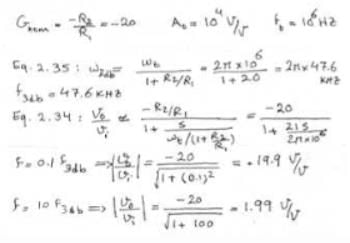
An inverting amplifier with nominal gain of −20 V/V employs an op amp having a dc gain of 104 and a unity-gain frequency of 106 Hz. What is the 3-dB frequency f3dB of the closed-loop amplifier?- a)2π 23.8 kHz
- b)2π 47.6 kHz
- c)2π 71.4 kHz
- d)2π 95.2 kHz
Correct answer is option 'B'. Can you explain this answer?
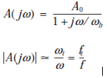
An inverting amplifier with nominal gain of −20 V/V employs an op amp having a dc gain of 104 and a unity-gain frequency of 106 Hz. What is the 3-dB frequency f3dB of the closed-loop amplifier?
a)
2π 23.8 kHz
b)
2π 47.6 kHz
c)
2π 71.4 kHz
d)
2π 95.2 kHz

|
Mrinalini Sen answered |
The frequency transfer function of a differentiator is given by- a)jωCR
- b)1/jωCR
- c)– jωCR
- d)– 1/jωCR
Correct answer is option 'A'. Can you explain this answer?
The frequency transfer function of a differentiator is given by
a)
jωCR
b)
1/jωCR
c)
– jωCR
d)
– 1/jωCR

|
Devanshi Iyer answered |
Standard mathematical expression for the transfer function of a differentiator.
For designing a non-inverting amplifier with a gain of 2 at the maximum output voltage of 10 V and the current in the voltage divider is to be 10 μA the resistance required are R1 and R2where R2 is used to provide negative feedback. Then- a)R1 = 0.5 MΩ and R2 = 0.5 MΩ
- b)R1 = 0.5 kΩ and R2 = 0.5 kΩ
- c)R1 = 5 MΩ and R2 = 5 MΩ
- d)R1 = 5 kΩ and R2 = 5 kΩ
Correct answer is option 'A'. Can you explain this answer?
For designing a non-inverting amplifier with a gain of 2 at the maximum output voltage of 10 V and the current in the voltage divider is to be 10 μA the resistance required are R1 and R2where R2 is used to provide negative feedback. Then
a)
R1 = 0.5 MΩ and R2 = 0.5 MΩ
b)
R1 = 0.5 kΩ and R2 = 0.5 kΩ
c)
R1 = 5 MΩ and R2 = 5 MΩ
d)
R1 = 5 kΩ and R2 = 5 kΩ
|
|
Jatin Mukherjee answered |
To design a non-inverting amplifier with a gain of 2 and a maximum output voltage of 10 V, we can use the following circuit:

Here, R1 and R2 form a voltage divider to set the input voltage. The gain of the amplifier is given by:
Gain = 1 + R2/R1
We want a gain of 2, so we can choose R1 = 10 kΩ and R2 = 10 kΩ. This gives us a gain of:
Gain = 1 + 10/10 = 2
To ensure that the maximum output voltage is 10 V, we need to choose a power supply voltage that is higher than 10 V. Let's choose a power supply voltage of 12 V.
To calculate the values of R3 and R4, we need to first calculate the current in the voltage divider. Let's assume that the input voltage is 5 V. Then the current in the voltage divider is:
I = (12 V - 5 V)/(10 kΩ + 10 kΩ) = 0.35 mA
We want the current in the voltage divider to be 10 times smaller than the input bias current of the op-amp. Let's assume that the input bias current is 10 nA. Then we can choose R3 and R4 such that the current flowing through them is 1 nA.
Let's choose R3 = R4 = 1 MΩ. Then the current flowing through R3 and R4 is:
I = (12 V - Vout)/2 MΩ = 1 nA
Solving for Vout, we get:
Vout = 12 V - 2 MΩ * 1 nA = 10 V
This confirms that the maximum output voltage is 10 V.
Therefore, the values of the resistors for the non-inverting amplifier with a gain of 2 and a maximum output voltage of 10 V, with a current in the voltage divider of 10, are:
R1 = 10 kΩ
R2 = 10 kΩ
R3 = 1 MΩ
R4 = 1 MΩ
One of the DC imperfections of the amplifiers are dc offset voltage which is- a)Existence of output signal even when the common mode signal is zero
- b)Existence of common mode signal causing zero output signal
- c)Existence of output signal even when the differential signal is zero
- d)Existence of differential signal causing zero output signal
Correct answer is option 'C'. Can you explain this answer?
One of the DC imperfections of the amplifiers are dc offset voltage which is
a)
Existence of output signal even when the common mode signal is zero
b)
Existence of common mode signal causing zero output signal
c)
Existence of output signal even when the differential signal is zero
d)
Existence of differential signal causing zero output signal
|
|
Anshu Kumar answered |
DC offset voltage is existence of output signal even when the differential signal is zero.
In the non-inverting configuration of operational amplifier- a)The positive terminal is connected to the ground directly
- b)The negative terminal is connected to the ground directly
- c)The positive terminal is connected to the power source
- d)The negative terminal is connected to the power source
Correct answer is option 'C'. Can you explain this answer?
In the non-inverting configuration of operational amplifier
a)
The positive terminal is connected to the ground directly
b)
The negative terminal is connected to the ground directly
c)
The positive terminal is connected to the power source
d)
The negative terminal is connected to the power source
|
|
Arindam Sengupta answered |
Non-Inverting Configuration of Operational Amplifier:
Operational amplifiers (op-amps) are widely used in electronic circuits for various applications. The non-inverting configuration is one of the most common configurations used in op-amp circuits.
Positive Terminal Connection:
In the non-inverting configuration of an operational amplifier, the positive terminal (+) is connected to the input signal source or voltage divider network. This is done to maintain a positive feedback loop in the circuit.
Negative Terminal Connection:
The negative terminal (-) of the operational amplifier is not directly connected to the ground in the non-inverting configuration. Instead, it is connected to a voltage divider network along with the output of the op-amp.
Positive Terminal Connection to Power Source:
The positive terminal of the op-amp is connected to the power source to provide the necessary biasing for the circuit. This ensures that the op-amp operates within its specified operating range.
Conclusion:
In the non-inverting configuration of an operational amplifier, the positive terminal is connected to the input signal source or voltage divider network, while the negative terminal is connected to a voltage divider network and the output of the op-amp. The positive terminal is also connected to the power source to provide the necessary biasing for the circuit. This configuration allows for a positive feedback loop and is commonly used in various electronic circuits.
Find the ft required for internally compensated op amps to be used in the implementation of the closed loop amplifiers with dc gain of -2 V/V and 3db bandwidth of 10 MHz?- a)7.5 MHz
- b)15 MHz
- c)22.5 MHz
- d)30 MHz
Correct answer is option 'D'. Can you explain this answer?
Find the ft required for internally compensated op amps to be used in the implementation of the closed loop amplifiers with dc gain of -2 V/V and 3db bandwidth of 10 MHz?
a)
7.5 MHz
b)
15 MHz
c)
22.5 MHz
d)
30 MHz
|
|
Bijoy Mehta answered |
Understanding the Requirements for Closed Loop Amplifiers
To design a closed-loop amplifier with a specific DC gain and bandwidth, we need to consider the gain-bandwidth product (GBP) of the operational amplifier (op-amp).
Key Concepts
- DC Gain: Given as -2 V/V, which indicates an inverting amplifier configuration.
- 3dB Bandwidth: Required bandwidth is 10 MHz.
Calculating the Required Gain-Bandwidth Product
The gain-bandwidth product (GBP) is a constant for a given op-amp. It can be expressed as:
GBP = Gain × Bandwidth
In this case, the gain is -2 (absolute value is considered):
- Gain (|A|) = 2 V/V
- Bandwidth (BW) = 10 MHz
Thus, the required GBP will be:
GBP = 2 V/V × 10 MHz = 20 MHz
Choosing the Appropriate Op-Amp
For an op-amp to successfully implement the closed-loop amplifier, its GBP must be equal to or greater than the calculated value of 20 MHz.
The required frequency for internally compensated op-amps typically needs to be higher than the desired bandwidth to account for the phase margin and stability.
Final Calculation for Required Frequency
To ensure stability and accommodate the closed-loop gain, we can estimate a safe operating frequency:
- A common rule of thumb is to use a frequency that is 1.5 to 2 times the GBP.
Therefore,
Required Frequency = 2 × 10 MHz = 20 MHz
Considering additional safety margins, a frequency of about 30 MHz is recommended for stability.
Conclusion
Based on these calculations, the correct option for the required frequency is:
Option 'D': 30 MHz
The integrating transfer function has the value of- a)jωCR
- b)–jωCR
- c)1 / jωCR
- d)-1 / jωCR
Correct answer is option 'D'. Can you explain this answer?
The integrating transfer function has the value of
a)
jωCR
b)
–jωCR
c)
1 / jωCR
d)
-1 / jωCR

|
Anushka Bose answered |
Standard mathematical expression for the transfer function.
The circuit is to operate at a temperature in the range 0°C to 75°C and the temperature coefficient of VOS is 10 μV/°C?- a)8.5 mV
- b)9 mV
- c)9.5 mV
- d)10 mV
Correct answer is option 'C'. Can you explain this answer?
The circuit is to operate at a temperature in the range 0°C to 75°C and the temperature coefficient of VOS is 10 μV/°C?
a)
8.5 mV
b)
9 mV
c)
9.5 mV
d)
10 mV

|
Moumita Kulkarni answered |
Since the effect is nullified at 25oC, the peak that can be sent now is given by 10 – (75-25) X 0.1 mV.
When does a resistance provide a negative feedback to an amplifier?- a)Resistance is connected between the positive input terminal and the output terminal
- b)Resistance is connected between the negative input terminal and the output terminal
- c)Resistance is connected between the input terminals
- d)Resistance is connected between the negative input terminal and ground
Correct answer is option 'B'. Can you explain this answer?
When does a resistance provide a negative feedback to an amplifier?
a)
Resistance is connected between the positive input terminal and the output terminal
b)
Resistance is connected between the negative input terminal and the output terminal
c)
Resistance is connected between the input terminals
d)
Resistance is connected between the negative input terminal and ground

|
Aditya Patel answered |
An op amp is said to have a negative feedback when a resistance is connected between the input and output terminals respectively.

For the amplifier shown determine the value of the bias current (Ib) and input offset current (Io) respectively.
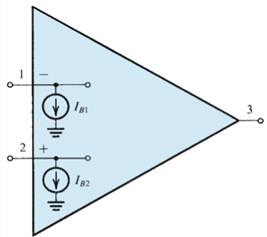
- a) Ib = IB1 + IB2 Io = IB1 – IB2
- b)Ib = IB1 + IB2 Io = | IB1 – IB2 |
- c)Ib = 0.5(IB1 + IB2) Io = | IB1 – IB2 |
- d)Ib = 0.5(IB1 + IB2) Io = IB1 – IB2
Correct answer is option 'C'. Can you explain this answer?
For the amplifier shown determine the value of the bias current (Ib) and input offset current (Io) respectively.
a)
Ib = IB1 + IB2 Io = IB1 – IB2
b)
Ib = IB1 + IB2 Io = | IB1 – IB2 |
c)
Ib = 0.5(IB1 + IB2) Io = | IB1 – IB2 |
d)
Ib = 0.5(IB1 + IB2) Io = IB1 – IB2
|
|
Sahana Chavan answered |
Standard mathematical expressions are used with the given variables.
Consider the figure given below. If the resistance R1 is disconnected from the ground and connected to a third power source v3, then expression for the value of v0 is
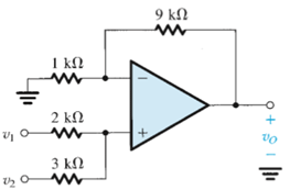
- a)2v1 + 4v2 − 3v3
- b)6v1 + 8v2 − 3v3
- c)6v1 + 4v2 − 9v3
- d)3v1 + 4v2 − 3v3
Correct answer is option 'C'. Can you explain this answer?
Consider the figure given below. If the resistance R1 is disconnected from the ground and connected to a third power source v3, then expression for the value of v0 is
a)
2v1 + 4v2 − 3v3
b)
6v1 + 8v2 − 3v3
c)
6v1 + 4v2 − 9v3
d)
3v1 + 4v2 − 3v3

|
Preethi Choudhury answered |
When a third power source is connected to the resistance of 1kΩ, then also the potential between the two input terminals of op amps remains the same. Using this fact the expression c is obtained.
The loop gain for an ideal operational amplifier with R1 = 10kΩ and R2(negative feedback) = 1MΩ is- a)20 db
- b)40 db
- c)60 db
- d)80 db
Correct answer is option 'B'. Can you explain this answer?
The loop gain for an ideal operational amplifier with R1 = 10kΩ and R2(negative feedback) = 1MΩ is
a)
20 db
b)
40 db
c)
60 db
d)
80 db
|
|
Neha Basak answered |
Loop gain in this case is given by 20 log (1000000/10000).
While performing an experiment to determine the gain for an ideal operational amplifier having finite gain, a student mistakenly used the equation 1 + R2/R1 where R2 is the feedback resistance. What is the percentage error in his result? Given A is the finite voltage gain of the ideal amplifier used.- a)(R2/R1)/(A+ R2/R1) X 100%
- b)(1+R2/R1)/(A+R2/R1) X 100%
- c)(1+R2/R1)/(A+1+R2/R1) X 100%
- d)(R2/R1)/(A+1+R2/R1) X 100%
Correct answer is option 'C'. Can you explain this answer?
While performing an experiment to determine the gain for an ideal operational amplifier having finite gain, a student mistakenly used the equation 1 + R2/R1 where R2 is the feedback resistance. What is the percentage error in his result? Given A is the finite voltage gain of the ideal amplifier used.
a)
(R2/R1)/(A+ R2/R1) X 100%
b)
(1+R2/R1)/(A+R2/R1) X 100%
c)
(1+R2/R1)/(A+1+R2/R1) X 100%
d)
(R2/R1)/(A+1+R2/R1) X 100%

|
Om Pillai answered |
The correct formula is (1+R2/R1)/(1+((1+R2/R1)/A)).
Chapter doubts & questions for Operational Amplifier - Analog and Digital Electronics 2025 is part of Electrical Engineering (EE) exam preparation. The chapters have been prepared according to the Electrical Engineering (EE) exam syllabus. The Chapter doubts & questions, notes, tests & MCQs are made for Electrical Engineering (EE) 2025 Exam. Find important definitions, questions, notes, meanings, examples, exercises, MCQs and online tests here.
Chapter doubts & questions of Operational Amplifier - Analog and Digital Electronics in English & Hindi are available as part of Electrical Engineering (EE) exam.
Download more important topics, notes, lectures and mock test series for Electrical Engineering (EE) Exam by signing up for free.
Analog and Digital Electronics
135 videos|167 docs|71 tests
|
|
© EduRev
|
Education Revolution
|


|


Signup to see your scores
go up
within 7 days!
within 7 days!
Takes less than 10 seconds to signup