


Computer Science Engineering (CSE) Exam > Computer Science Engineering (CSE) Questions > Find the maximum clock frequency at which the...
Start Learning for Free

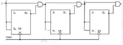
Find the maximum clock frequency at which the counter in the figure below can be operated. Assume that the propagation delay through each flip flop and each AND gate is 10 ns. Also assume that the setup time for the J K inputs of the flip flops is negligible.
Correct answer is '50'. Can you explain this answer?
| FREE This question is part of | Download PDF Attempt this Test |
Verified Answer
Find the maximum clock frequency at which the counter in the figure be...
In a JK flip flop the output toggles when both J and K inputs are 1. So, we must ensure that with each clock the output from the previous stage reaches the current stage. From the figure, there is an AND gate between each stage and  (10ns for output to reach the gate and 10ns for the output of AND gate to reach the next flipflop) isneeded for the output to reach the next stage. So, minimum time period needed for clock is 20ns which would mean a maximum clock frequency of
(10ns for output to reach the gate and 10ns for the output of AND gate to reach the next flipflop) isneeded for the output to reach the next stage. So, minimum time period needed for clock is 20ns which would mean a maximum clock frequency of Most Upvoted Answer
Find the maximum clock frequency at which the counter in the figure be...
In a JK flip flop the output toggles when both J and K inputs are 1. So, we must ensure that with each clock the output from the previous stage reaches the current stage. From the figure, there is an AND gate between each stage and (10ns for output to reach the gate and 10ns for the output of AND gate to reach the next flipflop) isneeded for the output to reach the next stage. So, minimum time period needed for clock is 20ns which would mean a maximum clock frequency of
(10ns for output to reach the gate and 10ns for the output of AND gate to reach the next flipflop) isneeded for the output to reach the next stage. So, minimum time period needed for clock is 20ns which would mean a maximum clock frequency of Free Test
FREE
| Start Free Test |
Community Answer
Find the maximum clock frequency at which the counter in the figure be...
In a JK flip flop the output toggles when both J and K inputs are 1. So, we must ensure that with each clock the output from the previous stage reaches the current stage. From the figure, there is an AND gate between each stage and (10ns for output to reach the gate and 10ns for the output of AND gate to reach the next flipflop) isneeded for the output to reach the next stage. So, minimum time period needed for clock is 20ns which would mean a maximum clock frequency of
(10ns for output to reach the gate and 10ns for the output of AND gate to reach the next flipflop) isneeded for the output to reach the next stage. So, minimum time period needed for clock is 20ns which would mean a maximum clock frequency of Attention Computer Science Engineering (CSE) Students!
To make sure you are not studying endlessly, EduRev has designed Computer Science Engineering (CSE) study material, with Structured Courses, Videos, & Test Series. Plus get personalized analysis, doubt solving and improvement plans to achieve a great score in Computer Science Engineering (CSE).


|
Explore Courses for Computer Science Engineering (CSE) exam
|
|
Similar Computer Science Engineering (CSE) Doubts


Top Courses for Computer Science Engineering (CSE)View all


Find the maximum clock frequency at which the counter in the figure below can be operated. Assume that the propagation delay through each flip flop and each AND gate is 10 ns. Also assume that the setup time for the J Kinputs of the flip flops is negligible.Correct answer is '50'. Can you explain this answer?
Question Description
Find the maximum clock frequency at which the counter in the figure below can be operated. Assume that the propagation delay through each flip flop and each AND gate is 10 ns. Also assume that the setup time for the J Kinputs of the flip flops is negligible.Correct answer is '50'. Can you explain this answer? for Computer Science Engineering (CSE) 2024 is part of Computer Science Engineering (CSE) preparation. The Question and answers have been prepared according to the Computer Science Engineering (CSE) exam syllabus. Information about Find the maximum clock frequency at which the counter in the figure below can be operated. Assume that the propagation delay through each flip flop and each AND gate is 10 ns. Also assume that the setup time for the J Kinputs of the flip flops is negligible.Correct answer is '50'. Can you explain this answer? covers all topics & solutions for Computer Science Engineering (CSE) 2024 Exam. Find important definitions, questions, meanings, examples, exercises and tests below for Find the maximum clock frequency at which the counter in the figure below can be operated. Assume that the propagation delay through each flip flop and each AND gate is 10 ns. Also assume that the setup time for the J Kinputs of the flip flops is negligible.Correct answer is '50'. Can you explain this answer?.
Find the maximum clock frequency at which the counter in the figure below can be operated. Assume that the propagation delay through each flip flop and each AND gate is 10 ns. Also assume that the setup time for the J Kinputs of the flip flops is negligible.Correct answer is '50'. Can you explain this answer? for Computer Science Engineering (CSE) 2024 is part of Computer Science Engineering (CSE) preparation. The Question and answers have been prepared according to the Computer Science Engineering (CSE) exam syllabus. Information about Find the maximum clock frequency at which the counter in the figure below can be operated. Assume that the propagation delay through each flip flop and each AND gate is 10 ns. Also assume that the setup time for the J Kinputs of the flip flops is negligible.Correct answer is '50'. Can you explain this answer? covers all topics & solutions for Computer Science Engineering (CSE) 2024 Exam. Find important definitions, questions, meanings, examples, exercises and tests below for Find the maximum clock frequency at which the counter in the figure below can be operated. Assume that the propagation delay through each flip flop and each AND gate is 10 ns. Also assume that the setup time for the J Kinputs of the flip flops is negligible.Correct answer is '50'. Can you explain this answer?.
Solutions for Find the maximum clock frequency at which the counter in the figure below can be operated. Assume that the propagation delay through each flip flop and each AND gate is 10 ns. Also assume that the setup time for the J Kinputs of the flip flops is negligible.Correct answer is '50'. Can you explain this answer? in English & in Hindi are available as part of our courses for Computer Science Engineering (CSE).
Download more important topics, notes, lectures and mock test series for Computer Science Engineering (CSE) Exam by signing up for free.
Here you can find the meaning of Find the maximum clock frequency at which the counter in the figure below can be operated. Assume that the propagation delay through each flip flop and each AND gate is 10 ns. Also assume that the setup time for the J Kinputs of the flip flops is negligible.Correct answer is '50'. Can you explain this answer? defined & explained in the simplest way possible. Besides giving the explanation of
Find the maximum clock frequency at which the counter in the figure below can be operated. Assume that the propagation delay through each flip flop and each AND gate is 10 ns. Also assume that the setup time for the J Kinputs of the flip flops is negligible.Correct answer is '50'. Can you explain this answer?, a detailed solution for Find the maximum clock frequency at which the counter in the figure below can be operated. Assume that the propagation delay through each flip flop and each AND gate is 10 ns. Also assume that the setup time for the J Kinputs of the flip flops is negligible.Correct answer is '50'. Can you explain this answer? has been provided alongside types of Find the maximum clock frequency at which the counter in the figure below can be operated. Assume that the propagation delay through each flip flop and each AND gate is 10 ns. Also assume that the setup time for the J Kinputs of the flip flops is negligible.Correct answer is '50'. Can you explain this answer? theory, EduRev gives you an
ample number of questions to practice Find the maximum clock frequency at which the counter in the figure below can be operated. Assume that the propagation delay through each flip flop and each AND gate is 10 ns. Also assume that the setup time for the J Kinputs of the flip flops is negligible.Correct answer is '50'. Can you explain this answer? tests, examples and also practice Computer Science Engineering (CSE) tests.
|
|
Explore Courses for Computer Science Engineering (CSE) exam
|
|
Suggested Free Tests
Signup for Free!
Signup to see your scores go up within 7 days! Learn & Practice with 1000+ FREE Notes, Videos & Tests.
|
© EduRev
|
Education Revolution
|


Follow Us
|


Signup on EduRev and stay on top of your study goals
10M+ students crushing their study goals daily