Diagram Based Questions: Electricity | Science Class 10 PDF Download

Q1: Answer the following questions based on the diagram given below:
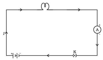
(i) What is the purpose of including a cell in this electric circuit?
Ans: The cell provides the source of electrical energy to the circuit, allowing current to flow and the bulb to light up.
(ii) Explain the function of the electric bulb in this circuit.
Ans: The electric bulb is a component that emits light when electricity passes through it. In this circuit, it lights up when the circuit is complete.
(iii) Why is an ammeter included in this circuit, and what does it measure?
Ans: The ammeter is included to measure the electric current flowing through the circuit. It measures the amount of current in amperes (A).
(iv) What role does the plug key play in this experiment?
Ans: The plug key is a switch that can open or close the circuit. When it is closed (turned on), the circuit is complete, and current flows. When it is open (turned off), the circuit is broken, and current stops.
(v) What will happen to the electric bulb if the plug key is opened (turned off)?
Ans: When the plug key is opened (turned off), the circuit is broken, and the electric bulb will not light up. It will remain off as long as the key is open.
Q2: Answer the following questions based on the diagram given below: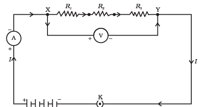
(i) What does the diagram show regarding the arrangement of resistors?
Ans: The diagram shows that the resistors are connected end-to-end in a single path, one after the other, forming a series circuit.
(ii) How does the total resistance in a series circuit compare to the individual resistances of the resistors?
Ans: In a series circuit, the total resistance is equal to the sum of the individual resistances of all the resistors connected in series.
(iii) If two resistors, one with resistance 3 ohms and another with resistance 4 ohms, are connected in series, what is the total resistance of the circuit?
Ans: The total resistance of the circuit will be 3 ohms + 4 ohms = 7 ohms.
(iv) What happens to the current flowing through each resistor in a series circuit when additional resistors are added to the circuit?
Ans: In a series circuit, adding more resistors increases the total resistance of the circuit, which in turn reduces the overall current flowing through the entire circuit, including each resistor.
(v) If a 12-volt battery is connected to a series circuit with three resistors, each with a resistance of 6 ohms, what will be the total current flowing through the circuit?
Ans: To find the total current, we can use Ohm's Law: I (current) = V (voltage) / R (total resistance). In this case, I = 12 volts / (6 ohms + 6 ohms + 6 ohms) = 12 volts / 18 ohms = 2/3 amperes (or 0.67 amperes). So, the total current flowing through the circuit will be approximately 0.67 amperes.
Q3: Answer the following questions based on the diagram given below: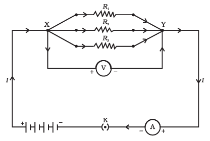
(i) What is meant by resistors in parallel?
Ans: Resistors in parallel are a configuration where two or more resistors are connected to the same two points in a circuit. In this setup, the current has multiple pathways to flow, and each resistor offers its own path for the current.
(ii) How does the total resistance of resistors in parallel compare to the individual resistances?
Ans: The total resistance of resistors in parallel is less than the smallest individual resistance. In other words, it is smaller than any single resistor in the parallel arrangement.
(iii) What happens to the total current when resistors are connected in parallel?
Ans: When resistors are connected in parallel, the total current flowing through the circuit increases compared to a single resistor. This is because the total resistance decreases, allowing more current to flow.
(iv) Can you explain why appliances in our homes are connected in parallel rather than in series?
Ans: Appliances in our homes are connected in parallel because if they were connected in series, the total resistance would be too high, and the current would be insufficient to power all the appliances simultaneously. Parallel connections ensure that each appliance gets the required voltage and can operate independently.
(v) How can you calculate the total resistance of resistors in parallel?
Ans: To calculate the total resistance (Rtotal) of resistors in parallel, you can use the formula: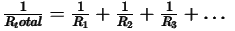
Where R1, R2, R3, etc., are the individual resistances. Simply find the reciprocals of each resistor's resistance, add them up, and then take the reciprocal of the sum to get Rtotal.
|
80 videos|569 docs|80 tests
|
FAQs on Diagram Based Questions: Electricity - Science Class 10
| 1. What is electricity? |  |
| 2. How is electricity generated? | |
| 3. What is the difference between AC and DC electricity? | |
| 4. What are the units used to measure electricity? | |
| 5. How does electricity travel through a circuit? | |


Diagram Based Questions: Electricity | Science Class 10
,MCQs
,Semester Notes
,Diagram Based Questions: Electricity | Science Class 10
,Sample Paper
,Extra Questions
,Diagram Based Questions: Electricity | Science Class 10
,Exam
,video lectures
,ppt
,mock tests for examination
,Free
,practice quizzes
,Summary
,study material
,Viva Questions
,past year papers
,Important questions
,Objective type Questions
,shortcuts and tricks
,Previous Year Questions with Solutions
;


Diagram Based Questions: Electricity Free PDF Download
Importance of Diagram Based Questions: Electricity
Diagram Based Questions: Electricity Notes
Diagram Based Questions: Electricity Class 10
Study Diagram Based Questions: Electricity on the App
|
© EduRev
|
Education Revolution
|


|


