Electric Circuits, Circuit Diagram & Ohm's Law | Science Class 10 PDF Download

Electric Circuits and Measuring Instruments
An electric circuit is a closed path that allows current to flow. This circuit may contain various electric components such as:
- Bulbs (or lamps)
- Cells
- Switches (or plug keys)
- Metal wires
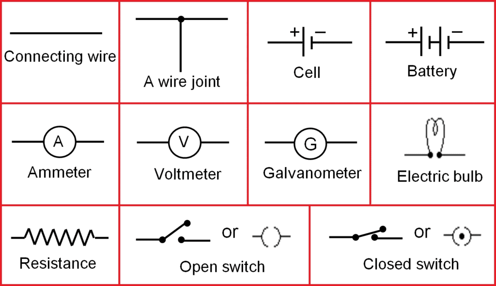
Each component has a specific role. For instance, wires connect components, while a switch can complete or break the circuit, controlling the current flow. A schematic diagram is often drawn to represent these components using standard symbols. These symbols are defined in a reference table.
Some common circuit elements and their symbols.
Common Measuring Instruments
To measure the electric current in a circuit, we use an ammeter, while a voltmeter measures the potential difference between two points. Both instruments feature a needle that moves over a graduated scale to indicate the measured value.
Each meter has two terminals:
- The terminal marked ' ' connects to the higher-potential side of the circuit.
- The terminal marked '-' connects to the lower-potential side.
The SI unit of electric current is the ampere. To initiate the flow of electrons in a circuit, we use a cell or a battery, which generates a potential difference measured in volts (V). Resistance, measured in ohms (Ω), is a property that opposes the flow of electrons and regulates the current. According to Ohm's law, the potential difference across a resistor is directly proportional to the current flowing through it, as long as the temperature remains constant.
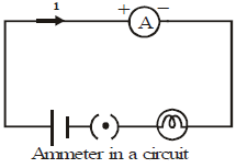
Using an Ammeter to measure Current
To measure the current through an element of a circuit, an ammeter is connected in such a way that the current flowing through it also flows through the element. Such a connection is called a series connection. In Figure, the current i flowing through the lamp also flows through the ammeter. The reading of the ammeter gives the current through the lamp. Note that if the ammeter is removed, there will be a gap, and the current through the circuit will stop.
Two or more electric elements are said to be connected in series if the current flowing through one also flows through the rest.
An ammeter is always connected in series in a circuit.
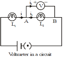
Using a Voltmeter to measure Potential Difference
To check the potential difference across a lamp (L2), a voltmeter is connected across two points (A and B) of the lamp:
- The positive terminal of the voltmeter attaches to point A, which has a higher potential.
- The negative terminal connects to point B.
- The voltmeter reading indicates the potential difference across L2.
- The current through the voltmeter is very small compared to the current in the rest of the circuit.
- Even with the voltmeter removed, the current continues to flow in the circuit.
- The potential difference across L2 and the voltmeter is the same.
- The voltmeter is connected in parallel to measure the potential difference, while the overall circuit may contain series connections.
Definition of Parallel Connection: Two or more electric elements are connected in parallel if the same potential difference is across them.
Ohm's Law
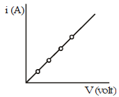
The electric current through a metallic element or wire is directly proportional to the potential difference applied between its ends, provided the temperature remains constant.
If a potential difference V is applied to an element and a current i passes through it,
i ∝ V
or 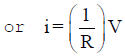
Thus Ohm's Law V = iR
Here R is a constant for the given element (metallic wire) at a given temperature and is called its resistance. It is the property of a conductor to resist the flow of charges through it.
Resistance
From equation, 
So, for a given potential difference, 
Thus, for a given potential difference, the current is inversely proportional to the resistance. The higher is the resistance, the lower is the current. If the resistance is doubled, the current is halved. Good conductors have low resistance, while insulators have very high resistance.
Unit of Resistance
Potential difference is measured in volts, and current is measured in amperes. From Equation, R = V/i. So, the unit of resistance is volt/ampere. This unit is called the ohm, and its symbol is W. We can define one ohm as follows.
If a potential difference of 1 volt is applied across an element, and a current of 1 ampere passes through it, the resistance of the element is called 1 ohm.
Factors on which the Resistance of a Conductor Depends
The resistance of the conductor depends:
(i) on its length,
(ii) on its area of cross-section, and
(iii) on the nature of its material.
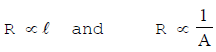
Resistance of a uniform metallic conductor is directly proportional to its length (l) and inversely proportional to the area of cross-section (A).
Combining eqs. we get
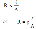
Where ρ(rho) is a constant of proportionality and is called electrical resistivity of the material of the conductor. The SI unit of resistivity is Ωm.
|
80 videos|569 docs|80 tests
|
FAQs on Electric Circuits, Circuit Diagram & Ohm's Law - Science Class 10
| 1. What is Ohm's Law? |  |
| 2. What is the relationship between voltage, current, and resistance in an electric circuit? | |
| 3. What is the purpose of measuring instruments in electric circuits? | |
| 4. What is the significance of circuit diagrams in understanding electric circuits? | |
| 5. Can Ohm's Law be applied to all electric circuits? | |


Circuit Diagram & Ohm's Law | Science Class 10
,Electric Circuits
,past year papers
,Sample Paper
,Circuit Diagram & Ohm's Law | Science Class 10
,shortcuts and tricks
,Objective type Questions
,Electric Circuits
,practice quizzes
,video lectures
,mock tests for examination
,Free
,Circuit Diagram & Ohm's Law | Science Class 10
,Extra Questions
,Exam
,Summary
,Semester Notes
,Previous Year Questions with Solutions
,MCQs
,ppt
,study material
,Viva Questions
,Important questions
,Electric Circuits
,


Electric Circuits, Circuit Diagram & Ohm's Law Free PDF Download
Importance of Electric Circuits, Circuit Diagram & Ohm's Law
Electric Circuits, Circuit Diagram & Ohm's Law Notes
Electric Circuits, Circuit Diagram & Ohm's Law Class 10 Questions
Study Electric Circuits, Circuit Diagram & Ohm's Law on the App
|
© EduRev
|
Education Revolution
|


|


within 7 days!