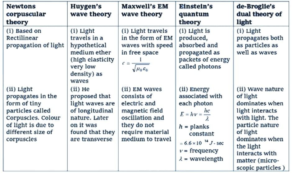
Introduction to Wave Optics


Wave Optics
A study of light that emphasises its wave nature and the consequences of superposition of light waves. Wave optics explains phenomena that cannot be fully accounted for by ray optics, such as interference, diffraction and polarisation. It also provides the basis for understanding how light interacts with materials and underlies technologies such as lenses, microscopes, and optical fibres.
- The wave theory treats light as a transverse wave propagating through space (or, historically, a medium).
- The speed of light in vacuum is constant; in materials the speed is determined by the medium's electromagnetic properties.
- Wave optics explains many phenomena which show the wave character of light, especially where phase relationships between waves matter.
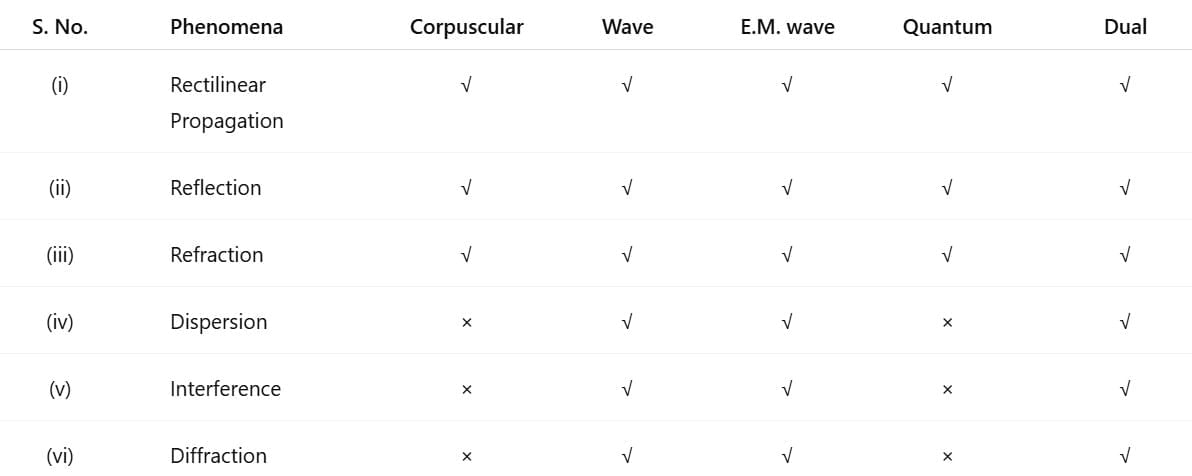
Some optical phenomena explained (✔) or not explained (✖) by different theories of light:
Wavefront
A wavefront is a surface joining all points of a wave that are in the same phase of vibration at a given instant.
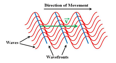 Wavefront
- It was suggested by Huygens.
- The direction of propagation of light (ray of light) is perpendicular to the wave front.
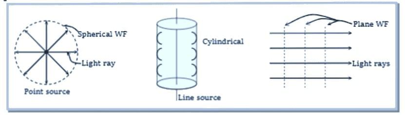
- There are three types of wavefront:
(a) Spherical wavefront - When light originates from a point source, the wavefronts take on a spherical shape.
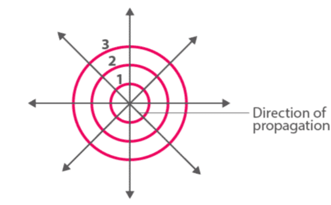
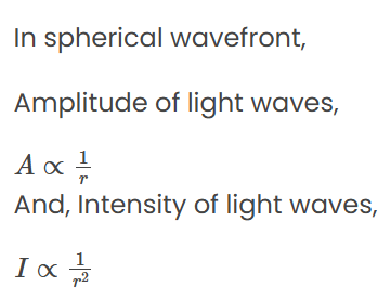
∴ Intensity (I) ∝ (Amplitude)2
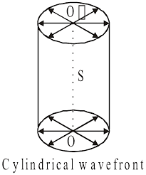
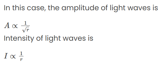
(b) Cylindrical wavefront - When the light comes from a linear source, the wavefronts are cylindrical in shape, with all points being equally distant from the source.
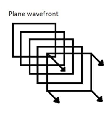
(c) Plane wavefront - When light comes from a distant source, the wavefronts become flat, or planar. In a plane wavefront, the amplitude stays the same, which means the intensity also remains constant.
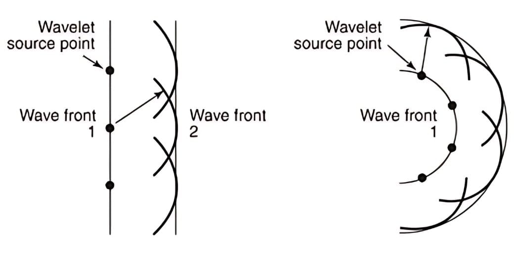
- Each point on a wavefront acts as a source of a new disturbance, known as secondary wavelets. These wavelets spread out in all directions at the speed of light in the medium.
- A surface that touches these secondary wavelets tangentially and moves forward at any moment creates the new wavefront at that instant. This is known as the secondary wavefront.
TIP: Imagine wavefronts like the ripples that form on a pond when you toss a stone into the water. The expanding circles are similar to spherical wavefronts in light.
 Ripples on a Pond
Huygens' Principle
A wavefront at any instant is the collection of all particles in a medium that are disturbed simultaneously and are in the same phase of vibration.
- Each point on a wavefront acts as a source of secondary disturbances, called secondary wavelets. These wavelets spread out in all directions at the speed of propagation in the medium.
- The position of the wavefront after a small time is given by the common tangent (envelope) to these secondary wavelets.
 Huygen's Principle
Maxwell's Electromagnetic Wave Theory
Light is an electromagnetic disturbance consisting of mutually perpendicular oscillating electric and magnetic fields that propagate through space.
Key points:
- Electromagnetic radiation carries radiant energy emitted by sources.
- The electric and magnetic fields oscillate perpendicular to each other and to the direction of propagation.
- Electromagnetic waves do not require a material medium for propagation.
- These waves travel at the speed of light in vacuum, and at lower speed in material media.
Electromagnetic Wave
- Light waves are electromagnetic waves which do not require a material medium for their propagation.
- Due to transverse nature, light wave undergo polarisation.
- The velocity of electromagnetic wave in vacuum is c = 1 / √μo εo.
- The velocity of electromagnetic waves in medium is less than that of light, v < c
v = 1 / √μo εo εr μr = c / √μo εr - The velocity of electromagnetic waves in a medium depends upon the electric and magnetic properties of the medium.where, μo = absolute magnetic permeability and εo = absolute electrical permittivity of free space.
- The wave theory is not sufficient alone without quantum mechanics to explain the phenomenon of photoelectric effect, Compton effect and Raman effect.
 Electromagnetic Spectrum
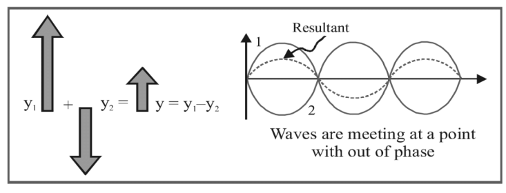
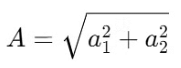
Superposition of Waves
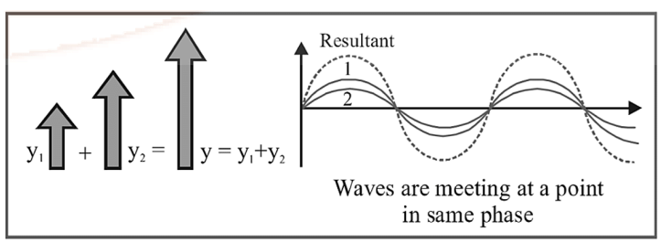
When two or more waves traverse the same region of space simultaneously, the resultant displacement at each point is the vector (algebraic, for one-dimensional oscillations) sum of the displacements due to the individual waves.
For two waves y1 and y2 the resultant is y = y1 + y2.
- Phase: the argument of the sine/cosine in the wave expression. For y = a sin(ωt + φ) the quantity (ωt + φ) is the instantaneous phase.
- Phase difference (φ): difference in phase between two waves at a point. Example: y1 = a sin(ωt), y2 = a sin(ωt + φ) → phase difference = φ.
- Path difference (Δ): the difference in distances travelled by two waves to reach a point. The relation between path difference and phase difference is φ = (2π / λ) Δ.
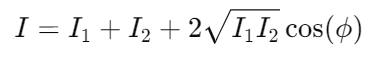
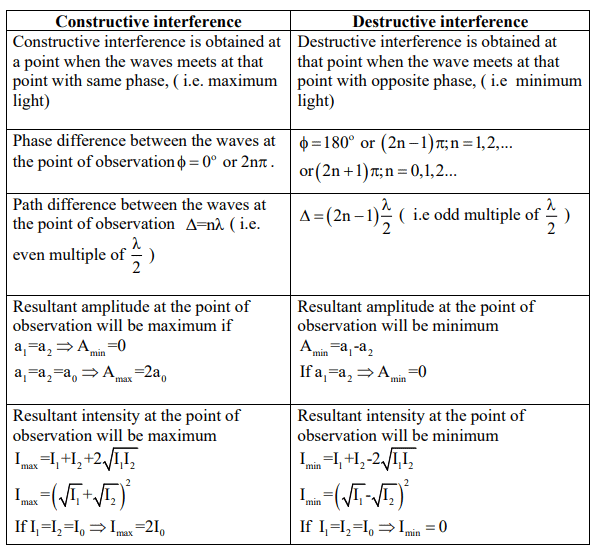
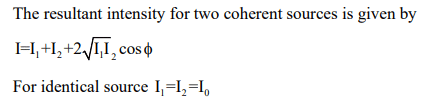
- Resultant amplitude and intensity: For two waves y1 = a1 sin(ωt) and y2 = a2sin(ωt + φ):
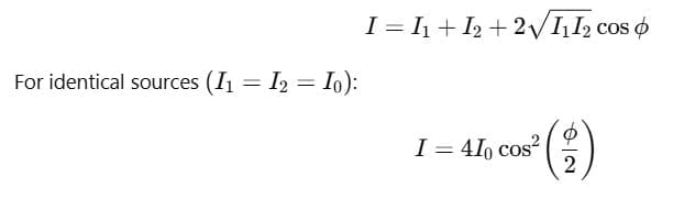
- Resultant amplitude A = √(a12 + a22 + 2 a1 a2 cos φ).
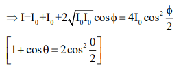
- Since intensity I ∝ A2, resultant intensity I = I1 + I2 + 2 √(I1 I2) cos φ, where I1 ∝ a12 and I2 ∝ a22.
- For two identical waves (a1 = a2 = a): resultant amplitude A = 2a cos(φ/2) and resultant intensity I = 4 I0 cos2(φ/2).
For the special case φ = π/2 (90°) the resultant amplitude reduces to the appropriate expression shown in the figure.
Intensity is proportional to the square of the amplitude, expressed as 𝐼 ∝ 𝐴2. Therefore, using the amplitudes, we can derive the formula for resultant intensity as:
The term 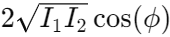 is known as the interference term. In cases of incoherent interference, this term is zero, leading to the resultant intensity simply being:
Interference of Light
- When two light waves of the same frequency and having a constant phase difference meet, their superposition produces regions of maximum intensity (constructive interference) and minimum intensity (destructive interference).
- This spatial redistribution of energy due to wave superposition is called interference.
Fringe Width
Fringe width (β) is the distance between centres of two consecutive bright (or dark) fringes.
For a typical Young's double-slit arrangement with two slits separated by distance d and an observation screen at distance D from the slits (D ≫ d), fringe width is:
β = λ D / d
Angular fringe separation θ between adjacent bright fringes is approximately θ = λ / d (small-angle approximation).
Types of interference:
Resultant intensity due to two identical waves
Coherent Sources of Light
Sources that emit light of the same wavelength and maintain a constant phase difference are called coherent sources.
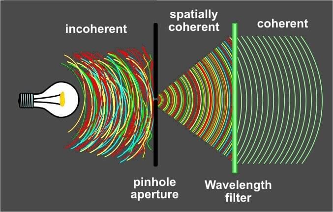 Coherent source of light
- Coherence is necessary for stable interference patterns. In practice, coherence is obtained by splitting light from a single source (so that the two emerging beams have a fixed phase relation), for example by using two slits or beam splitters.
- When a transparent sheet (refractive index μ, thickness t) is introduced in one path of interfering waves, the fringe pattern shifts. The shift Y (measured in fringe widths or distance on the screen) is given by:
- Y = (D / d) (μ - 1) t = (β / λ) (μ - 1) t, where β is fringe width and λ wavelength in air.
Illustrations of Interference
Thin films and related arrangements show vivid interference effects when their thickness is comparable to the wavelength of light used.
- If the film thickness is very small compared to λ, reflected light may interfere destructively and the film looks dark for a particular wavelength.
- If thickness is large compared to λ, many fringes or uniform appearance may be observed depending on coherence.
- Examples: colours of oil films on water and soap bubbles arise from interference of light reflected from the two surfaces of the film.
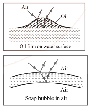
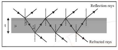
Thin Films
Interference in thin films arises between waves reflected from the top and bottom surfaces of the film and waves transmitted through the film. Important points:
- A reflection from a medium of higher refractive index than the incident medium produces a phase change of π (equivalent to half a wavelength).
- Reflection from a lower-index medium produces no phase change.
- For normal incidence, effective path difference between the two reflected rays is 2 μ t(distance in the film counted with refractive index μ). Accounting for possible phase changes on reflection, conditions for constructive/destructive interference in reflected light are:
- If there is one phase reversal (net π from reflections): constructive interference (bright reflected) occurs when 2 μ t = (m + 1/2) λ (in air) and destructive when 2 μ t = m λ.
- If there are zero or two phase reversals: constructive interference in reflection occurs when 2 μ t = m λ and destructive when 2 μ t = (m + 1/2) λ.
- For transmitted light, the conditions are complementary to those for reflected light (bright reflected → dark transmitted, and vice versa), but care must be taken to include phase reversals correctly.
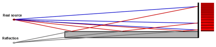
Lloyd's Mirror
- In Lloyd's mirror experiment a source S and its virtual image (produced by reflection in a plane mirror) act as two coherent sources separated by a small distance; interference fringes form on a screen.
- Because one beam undergoes a reflection that produces a π phase shift, the interference pattern is shifted: bright fringes occur where one would expect dark fringes without that π shift.
- Fringe condition (path difference Δx): minima (dark) when Δx = (2n - 1) λ / 2 and maxima (bright) when Δx = n λ (n = 0, 1, 2 ...), when taking the phase inversion into account.
 Llyod's Mirror
Reflection can change the expected positions of bright and dark fringes by introducing additional phase shifts.
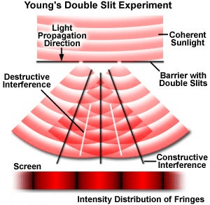
Young's Double Slit Experiment (YDSE)
Young's double slit experiment demonstrates the wave nature of light through the phenomenon of interference.
A monochromatic source of light S illuminates a narrow slit, which in turn illuminates two closely spaced narrow slits S1 and S2.
- The two slits act as coherent sources.
- A screen is placed at a distance D from the slits.
- Alternate bright and dark bands called interference fringes are observed on the screen.
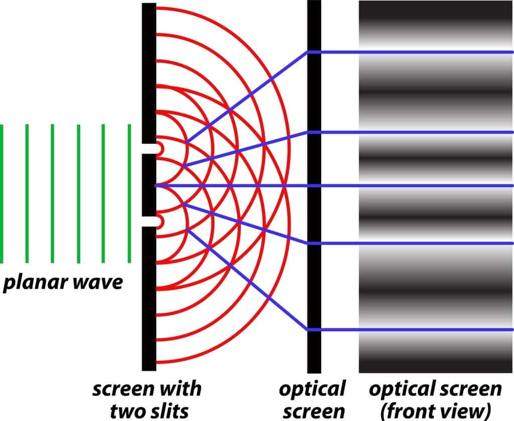
Principle
The pattern is formed due to interference of light waves coming from the two coherent sources S1 and S2.
Geometry of the Experiment
Let:
- d = distance between slits
- D = distance between slits and screen ( D ≫ d )
- y = distance of point P from central line
- λ = wavelength of light
Path Difference at Point P
Light travels from both slits to point P.
Δ = S2P - S1P
For small angles,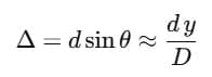
Conditions for Interference
(i) Constructive Interference (Bright Fringe)
Bright fringe is formed when waves arrive in phase.
Δ = nλ (n = 0,1,2,...)
(ii) Destructive Interference (Dark Fringe)
Dark fringe is formed when waves arrive out of phase.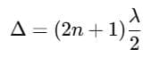 Position of Fringes
Substituting 
Position of Bright Fringe: 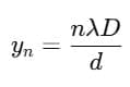
Position of Dark Fringe: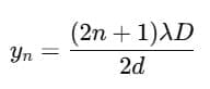
Fringe Width
The distance between two successive bright or dark fringes is called fringe width β.
Intensity Distribution
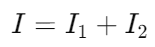
If intensities of waves from the two slits are I1 and I2, then resultant intensity at point P is:
Young's double slit experiment proves that light exhibits wave nature and undergoes interference.
FAQs on Introduction to Wave Optics
| 1. What is Huygen’s Principle and how is it applied in wave optics? |  |
| 2. How does the Doppler Effect apply to light and what are its implications? | |
| 3. What is the significance of interference of light in wave optics? | |
| 4. Can you explain Lloyd’s Mirror and its application in wave optics? | |
| 5. How does Maxwell’s electromagnetic wave theory relate to wave optics? | |


